
Adele
Engineering Graphics and Design P2 Grade 12 Questions - NSC Exams Past Papers and Memos September 2019 Preparatory Examinations
QUESTIONS

Electrical Technology: Digital Grade 12 Questions - NSC Exams Past Papers and Memos September 2019 Preparatory Examinations
INSTRUCTIONS AND INFORMATION
- This question paper consists of FIVE questions.
- Sketches and diagrams must be large, neat and fully labelled.
- Show ALL calculations and round off answers to TWO decimal places. Show the units for ALL answers and calculations.
- Number the answers correctly according to the numbering system used in this question paper.
- You may use a non-programmable calculator.
- A formula sheet is provided at the end of this question paper.
- Write neatly and legibly.
QUESTIONS
QUESTION 1: OCCUPATIONAL HEALTH AND SAFETY (GENERIC)
1.1 Name THREE unsafe conditions that cause most accidents in the workshop. (3)
1.2 Explain the purpose of the Occupational Health and Safety Act. (2)
1.3 Give TWO unsafe acts in a school workshop that can cause an accident. (2)
1.4 Describe THREE standard treatments for electric shock after the electricity has been removed. (3) [10]
QUESTION 2: SWITCHING CIRCUITS (GENERIC)
2.1 With reference to FIGURE 2.1, answer the following questions.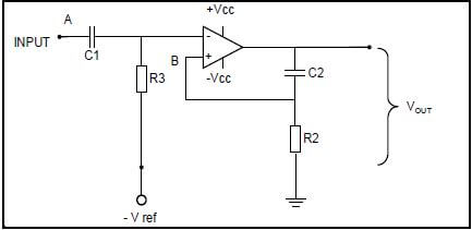
FIGURE 2.1: MULTIVIBRATOR
2.1.1 Identify the multivibrator in FIGURE 2.1. (1)
2.1.2 Name TWO characteristics of this multivibrator. (2)
2.1.3 Explain the function of the network C2 and R2. (3)
2.1.4 Analyse FIGURE 2.1 above and explain the THREE ways to change this circuit in order to have a variable time in the high state. (4)
2.1.5 Explain the principle of operation of the circuit in FIGURE 2.1. (8)
2.1.6 Name ONE application of this multivibrator. (1)
2.2 With reference to FIGURE 2.2, answer the following questions. 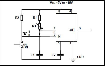
FIGURE 2.2: MULTIVIBRATOR
2.2.1 Explain the function of R1 in the circuit. (2)
2.2.2 Name TWO methods to vary the time period of this circuit. (2)
2.2.3 Explain the effect on the output waveform if R3 is changed from 10 kΩ to 27 kΩ. (1)
2.3 Draw a fully labelled circuit diagram of an Op-Amp Astable multivibrator circuit. (8)
2.4 Draw a fully labelled hysteresis characteristic curve with reference to the Schmitt trigger. (6)
2.5 Define the term hysteresis with reference to the Schmitt trigger. (2)
2.6 Name TWO applications of a Schmitt trigger. (2)
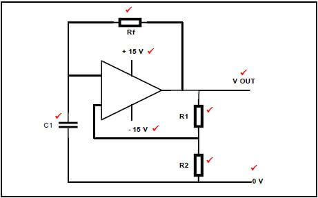
2.7 Draw a fully labelled circuit diagram of a temperature sensor circuit. (8)
2.8 Draw a fully labelled circuit diagram of a summing amplifier with three inputs. (6)
2.9 A summing amplifier has three input resistors with the following values:
R1 = 30 kΩ, R2 = 17 kΩ, R3 = 21 kΩ. The output voltage for this circuit is given as -2,7 V. The known input voltages are: V1 = 150 mV, V2 = 430 mV.
Calculate the value of V3 if this circuit has a 120 kΩ feedback resistor. (4) [60]
QUESTION 3: SEMICONDUCTOR DEVICES (SPECIFIC)
3.1 State the THREE stages of a 741 Op-Amp. (3)
3.2 Explain the term Common Mode Rejection Ratio. (2)
3.3 With reference to FIGURE 3.3 below, answer the following questions. 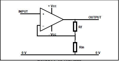
FIGURE 3.3: OP-AMPLIFIER
3.3.1 Identify the Op-Amplifier in FIGURE 3.3. (1)
3.3.2 Calculate the gain of the amplifier if the feedback resistor has a value of 1 kΩ and the input resistor has a value of 1 900 Ω. (2)
3.4 Name THREE uses for the 555 timer IC. (3)
3.5 Name TWO operating boundaries of a 555 timer IC. (2)
3.6 Explain why this IC is called a 555 timer IC. (3)
3.7 With reference to FIGURE 3.7 below, label pin 6.
3.7.1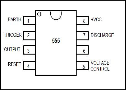
FIGURE 3.7: 555 TIMER (1)
3.7.2 With reference to a 555 timer IC, explain the function of pin 2 (trigger). (3) [20]
QUESTION 4: DIGITAL AND SEQUENTIAL DEVICES (SPECIFIC)
4.1 Explain the term common anode with reference to the seven segment LED display. (2)
4.2 Draw a fully labelled circuit diagram of a sinking digital output. (4)
4.3 Explain the term polarisation of light with reference to LCD displays. (3)
4.4 With reference to FIGURE 4.1 below, answer the questions to follow.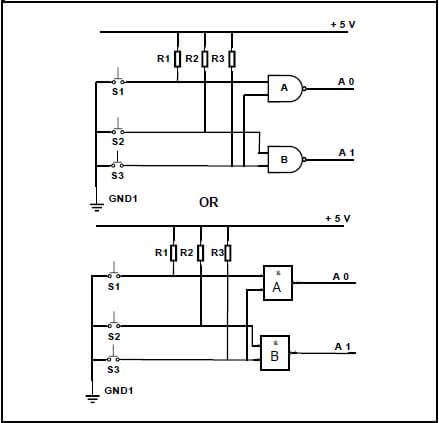
FIGURE 4.4: LOGIC CIRCUIT
4.4.1 Identify the circuit in FIGURE 4.4. (1)
4.4.2 Draw a truth table for the circuit in FIGURE 4.4. (5)
4.4.3 Explain the function of the circuit in FIGURE 4.4. (2)
4.5 Draw the logic symbol for a half adder. (2)
4.6 With reference to FIGURE 4.6 below, answer the questions to follow. 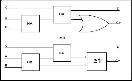
FIGURE 4.6: LOGIC CIRCUIT
4.6.1 Identify the circuit in FIGURE 4.6. (1)
4.6.2 Draw the fully labelled logic diagram for the logic circuit in FIGURE 4.6 using AND gates, EXCLUSIVE OR and OR gates. (8)
4.7 Draw a fully labelled logic circuit of an active high latch (RS Latch). (3)
4.8 Complete the truth table below for an active high latch.
MODE OF OPERATION INPUTS | INPUTS | OUTPUTS | ||
ILLEGAL | S | R | Q1 | Q2 |
0 | 0 | |||
SET | 0 | 1 | ||
RESET | 1 | 0 | ||
HOLD | 1 | 1 | ||
(4)
4.9 Draw a fully labelled circuit diagram of a D Latch flip-flop using NAND gates, EXCLUSIVE OR gates and INVERTER. (8)
4.10 Explain the term positive edge triggering. (2)
Copyright reserved Please turn over
10 ELECTRICAL TECHNOLOGY: DIGITAL (EC/SEPTEMBER 2019)
4.11 With reference to FIGURE 4.11 below, explain the principle of operation of an up/down counter.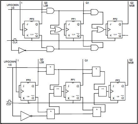
(8)
FIGURE 4.11: UP / DOWN COUNTER
4.12 Explain the term truncated counter. (2) [55]
QUESTION 5: MICROCONTROLLERS (SPECIFIC)
5.1 Give the definition of a microcontroller. (3)
5.2 Name TWO uses of microcontrollers as used in day-to-day life devices. (2)
5.3 Name the main disadvantage of a microcontroller. (2)
5.4 With reference to the parts of a microcontroller, answer the questions that follow:
5.4.1 Define the Central Processing Unit (CPU). (2)
5.4.2 Describe the function of the Input/Output interface (I/O). (2)
5.5 Briefly define integrated logic. (1)
5.6 Explain the function of each of the following registers with reference to the Central Processing Unit (CPU):
5.6.1 Program counter (3)
5.6.2 Memory data register (1)
5.7 Discuss the Random Access Memory (RAM) with reference to the CPU of a microcontroller. (5)
5.8 With reference to communication in a microcontroller, state the THREE BUSSES that the system bus consists of. (3)
5.9 Define communication protocol as an element in a microcontroller. (2)
5.10 Explain the differences between simplex communication and duplex communication by means of fully labelled block diagrams. (6)
5.11 Name TWO advantages of asynchronous communication. (2)
5.12 Draw a fully labelled block diagram of an 8-bit serial communication system. (7)
5.13 With reference to communication peripherals, name TWO advantages of the Serial Peripheral Interface (SPI). (2)
5.14 Identify the following flow diagram symbols.
5.14.1  (1)
(1)
5.14.2  (1)
(1)
5.15 Draw a flow diagram for a mono stable device that has only one stable state. The program switches the output on and off every 5 seconds and then returns to the original state. (10) [55]
TOTAL: 200
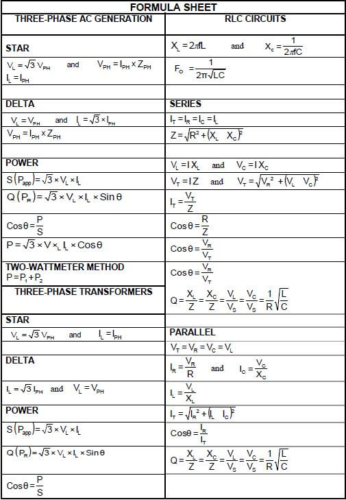
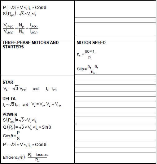
FORMULA SHEET - DIGITAL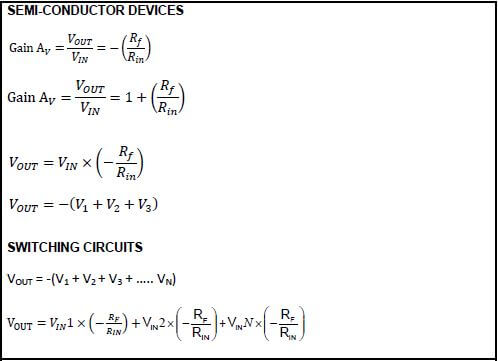
Electrical Technology: Digital Grade 12 Memorandum - NSC Exams Past Papers and Memos September 2019 Preparatory Examinations
INSTRUCTIONS TO MARKERS
- All questions with multiple answers imply that any relevant, acceptable answer should be considered.
- Calculations:
2.1 All calculations must show the formulae.
2.2 Substitution of values must be done correctly.
2.3 All answers MUST contain the correct unit to be considered.
2.4 Alternative methods must be considered, provided that the correct answer is obtained.
2.5 Where an incorrect answer could be carried over to the next step, the first answer will be deemed incorrect. However, should the incorrect answer be carried over correctly, the marker has to re-calculate the values, using the incorrect answer from the first calculation. If correctly used, the candidate should receive the full marks for subsequent calculations.
2.6 Markers should consider that candidates' answers may deviate slightly from the marking guideline depending on how and where in the calculation rounding off was used. - These marking guidelines are only a guide with model answers.
- Alternative interpretations must be considered and marked on merit. However, this principle should be applied consistently throughout the marking session at ALL marking centres.
MEMORANDUM
QUESTION 1: OCCUPATIONAL HEALTH AND SAFETY (GENERIC)
1.1
- Faulty tools or equipment ✔
- Poor ventilation ✔
- Poor quality or missing guards on machines ✔
- Excessive noise
- Lack of knowledge of emergency procedures
(Any THREE relevant answers) (3)
1.2 The purpose of the Occupational Health and Safety Act is to provide for the health and safety of:
- Persons at work ✔
- Persons in connection with the use of plant and machinery ✔
- The protection of persons against hazards arising out of the activities of other persons at work
- To establish an advisory council for occupational health and safety and related matters (2)
1.3
- Horseplay ✔
- Running in the workshop ✔
- Throwing things around
- Leaving bags stools or material in walkway
- Spilling a liquid or oil without cleaning
(Any relevant answers) (2)
1.4
- Keep person lying down ✔
- Cover the person to maintain body heat ✔
- Do not move the person in case of neck or spine injuries ✔
- If unconscious, put them on their side (recovery position)
(Any THREE relevant answers) (3) [10]
QUESTION 2: SWITCHING CIRCUITS (GENERIC)
2.1
2.1.1 Mono-stable multivibrator ✔ (1)
2.1.2
- It has ONE input ✔
- It has ONE stable state ✔ (2)
2.1.3
- The RC network in this circuit is the timing component of this circuit ✔
- The values of the resistor and the capacitor determines for how long the circuit will be in ‘HIGH’, ✔state before it reverts back to its stable ‘LOW’ state ✔ (3)
2.1.4
- By changing R2 from a fixed resistor value to a variable resistor ✔
- By changing the value of C2 from a fixed value capacitor to a variable capacitor ✔
- By changing both R2 and C2 from fixed values ✔ to variable values ✔ (4)
2.1.5
- When the circuit is in resting condition, the negative voltage of –Vref on the inverting input serves to hold this inverting input low ✔
- This will cause the Op-Amp to saturate and the output to rise to + 15 V ✔
- The capacitor, C, charges up with the top plate to + 15 V, and the bottom plate to 0 V ✔
- When the capacitor is charged, no current flows through R as there is no voltage over it. This holds the non-inverting input at 0 V ✔
- A positive trigger pulse larger than Vref applied to the inverting input terminal will raise the inverting input potential above the 0V of the non-inverting input ✔
- The Op-Amp will now saturate and the output will go to -15 V ✔
- The capacitor will now immediately start discharging through the resistor ✔
- The lower plate of the capacitor rises and when the voltage is less negative than Vref, the output changes to +15 V again ✔ (8)
2.1.6 Debouncing ✔ (1)
2.2
2.2.1 At one end the potentiometer will be connected to 0 Ω. ✔ R1 will prevent the full supply flowing to pin 6 and 7, when the potentiometer is in the 0 Ω position ✔ (2)
2.2.2
- By changing the value of C1 ✔
- By changing the value of R3 ✔ (2)
2.2.3 The time period will increase (1)
2.3
(8)
2.4
(6)
2.5 The time lag (delay) between cause ✔ and effect ✔ (2)
2.6
- First stage of many radio receivers to clean up noise ✔
- To eliminate switch bounce in digital circuits ✔
- Varying input waveforms, for instance sine wave changed into square wave or rectangular wave
- Signal recovery after experiencing severe distortion (2)
2.7
(8)
2.8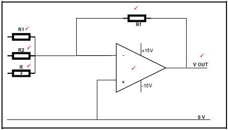
(6)
2.9 
(4) [60]
QUESTION 3: SEMI-CONDUCTOR DEVICES (SPECIFIC)
3.1
- Input stage (Differential amplifier) ✔
- Intermediate stage (High gain differential amplifier) ✔
- Common Collector (Darlington Pair) output stage ✔ (3)
3.2 The ability of the Op-Amp ✔ to suppress a common-anode ✔ is called the common-mode-rejection ratio (2)
3.3
3.3.1 Non-inverting Op-Amp (1)
3.3.2
- AV = 1 + Rf
Rin
= 1 + 1000
1900✔
= 1 + 0,526
= 1,526 ✔ (2)
3.4
- Basic timing function, e.g. turning a light on or off after a period of time ✔
- Pulse oscillation and wave generation ✔
- Creating a flashing warning light ✔
- Digital logic probes
- Producing musical notes of specific frequencies
- Temperature measurement
- Controlling the positioning of servo devices (3)
3.5
- Operate on supply voltages between +5 V to +18 V ✔
- The maximum current it can either sink or source is 200 mA ✔ (2)
3.6 In the construction of this IC there are three series connected resistors of identical value (5 kΩ). ✔ These resistors divide ✔ the voltages to 2/3 and 1/3 of the supply voltage ✔ (3)
3.7
3.7.1 Threshold ✔ (1)
3.7.2
- This pin sets off the IC
- It is an active low trigger ✔
- When the voltage on pin 2 is less than 13of the supply, the output goes high ✔
- When the voltage on pin 2 is higher than 23of the supply, the output will go low ✔
- If connected to ground, the output will go ‘high’ and remain ‘high’ (3) [20]
QUESTION 4: DIGITAL AND SEQUENTIAL DEVICES (SPECIFIC)
4.1 The anodes of all 8 LEDs are connected together ✔on the positive voltage rail ✔ (2)
4.2

(4)
4.3
- Light waves travel naturally in both the vertical and the horizontal planes ✔
- When the light passes through a filter which only allows a single plane of light to pass through and block the other plane of light, ✔
- it is called polarisation ✔ (3)
4.4
4.4.1 Encoder ✔ (1)
4.4.2
INPUTS | OUTPUTS ✔ | |
0 | A1 | A0 |
0 | 0 ✔ | |
1 | 0 | 1 ✔ |
2 | 1 | 0 ✔ |
3 | 1 | 1 ✔ |
(5)
4.4.3 An encoder accepts the input data in a decimal format ✔and converts it to binary format ✔ (2)
4.5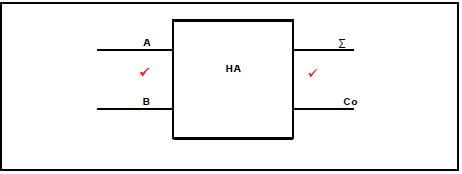
(2)
4.6.2 C 1
4.6
4.6.1 Full adder ✔ (1)
4.6.2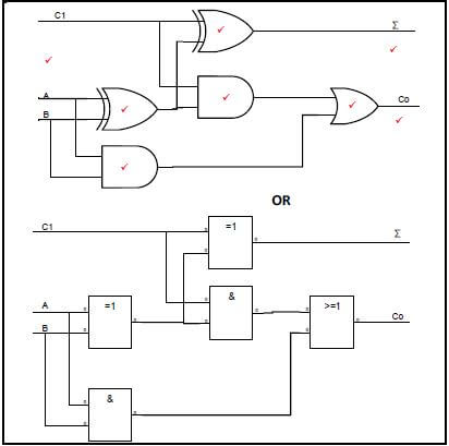
(8)
4.7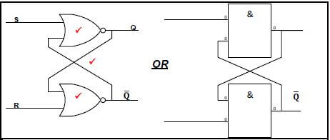
(3)
4.8
MODE OF OPERATION | INPUTS | OUTPUTS | ||
ILLEGAL | S | R | Q1 | Q2 |
0 | 0 | 0 | 0 ✔ | |
SET | 0 | 1 | 1 | 0 ✔ |
RESET | 1 | 0 | 0 | 1 ✔ |
HOLD | 1 | 1 | NO CHANGE ✔ | |
(4)
4.9 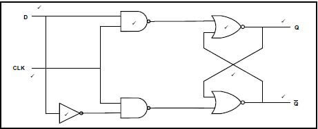
(8)
OR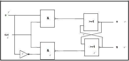
4.10 When a circuit reacts to the positive (rising) edge ✔ of the pulse going from 0 to 1 ✔ (2)
4.11
- The UP/DOWN counter control is dictated by the HIGH “1” or LOW “0” on the control line to determine the direction of counting
- If set to UP, the control line is high ✔
- This will enable the upper 2 AND gates to become active when they get a high from either FF0 or FF1 outputs
- Once activated, the AND gate between FF0 and FF1 will enable the high “1” output from Q0 to both J and K inputs of FF1 ✔
- Likewise, a high “1” output from FF1 will enable the 2nd AND gate to pass a high “1” to the J and K inputs of FF2 ✔
- In this way the circuit operates as a normal UP counter, advancing its count from 010 to 710 ✔
- If set to DOWN, the control line is set to LOW “0”. This will disable the upper 2 AND gates while presenting a LOW “0” at the input of the invertor
gate ✔ - A LOW “0” input will cause a HIGH “1” output at the invertor ✔
- This HIGH “1” will enable the 2 lower AND gates ✔
- When they receive a HIGH “0” from either of the 2 flip-flops, FF0 and FF1, they will place a HIGH “0” on the inputs of the next flip-flops ✔
- This enables them to toggle at the next clock pulse
- This circuit then operates as a normal down counter (8)
4.12 This is a counter which has been modified to stop its count at a pre-set value ✔ before reaching the maximum count ✔ (2) [55]
QUESTION 5: MICROCONTROLLERS (SPECIFIC)
5.1 It is an independent device, ✔a computer on a chip, that can perform a limited range of functions ✔without needing to rely on other chips or devices ✔ (3)
5.2
- Alarm monitoring and warning devices ✔
- Fire detection and safety devices ✔
- Temperature sensing and control
- Light sensing and control (2)
5.3 It has a very low output current, ✔only a few milli-amps, and therefore requires interfacing circuitry to drive higher current loads ✔ (2)
5.4
5.4.1 Central Processing Unit is responsible for interpreting ✔ and executing the stored instructions from the ROM program ✔ (2)
5.4.2 Input/Output communication lines enable the microprocessor to communicate ✔ with the outside world via interface connections as tracks on a board ✔ (2)
5.5 This is a single chip containing the entire processor ✔ (1)
5.6
5.6.1 Contains the address and status of the next instruction for processing. ✔Also tells the processor what the next instruction is. ✔ It also keeps count of the number of instructions that have been
executed ✔ (3)
5.6.2 Stores a copy of the current instruction been executed ✔ (1)
5.7
- RAM can both read data and have it written to ✔
- It can hold programmes, operating systems and data required by the system ✔
- It is known as a volatile memory as it loses all data stored when it loses power ✔
- RAM stores all the data that is required to be processed by the CPU during the execution of programmes ✔
- RAM consists of a list of addresses and in each address is a piece of data ✔ (5)
5.8
- Control bus ✔
- Data bus ✔
- Address bus ✔ (3)
5.9 A set of rules and regulations that allow 2 electronic devices ✔ to connect to exchange data and information between each other ✔ (2)
5.10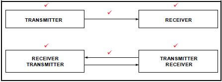
(6)
5.11
- No need for a synchronous clock pulse between sender and receiver ✔
- Peer-to-peer system where data can be transferred in both directions between the two devices ✔ (2)
5.12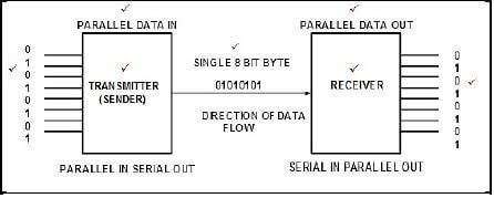
(7)
5.13
- Supports higher speed full duplex communication ✔
- Draws very little power ✔
- Can operate at extremely high speeds (millions of bits per second) (2)
5.14
5.14.1 Start/finish instruction ✔ (1)
5.14.2 Decision instruction ✔ (1)
5.15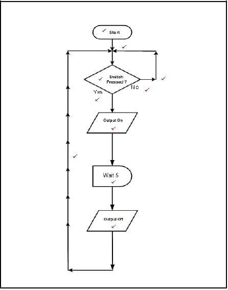
(10) [55]
TOTAL: 200
Electrical Technology: Power Systems Grade 12 Memorandum - NSC Exams Past Papers and Memos September 2019 Preparatory Examinations
INSTRUCTIONS TO MARKERS
- All questions with multiple answers imply that any relevant, acceptable answer should be considered.
- Calculations:
2.1 All calculations must show the formulae.
2.2 Substitution of values must be done correctly.
2.3 All answers MUST contain the correct unit to be considered.
2.4 Alternative methods must be considered, provided that the correct answer is obtained.
2.5 Where an incorrect answer could be carried over to the next step, the first answer will be deemed incorrect. However, should the incorrect answer be carried over correctly, the marker has to re-calculate the values, using the incorrect answer from the first calculation. If correctly used, the candidate should receive the full marks for subsequent calculations.
2.6 Markers should consider that candidates' answers may deviate slightly from the marking guideline depending on how and where in the calculation rounding off was used. - These marking guidelines are only a guide with model answers.
- Alternative interpretations must be considered and marked on merit. However, this principle should be applied consistently throughout the marking session at ALL marking centres.
MEMORANDUM
QUESTION 1: OCCUPATIONAL HEALTH AND SAFETY (GENERIC)
1.1
- Faulty tools or equipment ✔
- Poor ventilation ✔
- Poor quality or missing guards on machines. ✔
- Excessive noise
- Lack of knowledge of emergency procedures
(Any THREE relevant answers) (3)
1.2 The purpose of the Occupational Health and Safety Act is to provide for the health and safety of:
- Persons at work ✔
- Persons in connection with the use of plant and machinery ✔
- The protection of persons against hazards arising out of the activities of other persons at work
- To establish an advisory council for occupational health and safety and related matters (2)
1.3
- Horseplay ✔
- Running in the workshop ✔
- Throwing things
- Leaving bags, stools or material in walkway
- Spilling a liquid or oil without cleaning
- (Any relevant answer) (2)
1.4
- Keep person lying down ✔
- Cover the person to maintain body heat ✔
- Do not move the person in case of neck or spine injuries ✔
- If unconscious, put them on their side (recovery position)
(Any THREE relevant answers) (3) [10]
QUESTION 2: RLC CIRCUITS (GENERIC)
2.1 Q-factor for a parallel circuit concerns the relationship between the resistance and the reactance of the circuit. ✔ The Q-factor of the circuit is found from the ratio between the reactive components, either the inductive or capacitance at resonance, and the active power of the resistance. ✔ (2)
2.2 Factors that affect the impedance of an RLC circuit:
- Frequency ✔
- Inductance ✔
- Capacitance ✔ (3)
2.3
- Z = R ✔
- XL = XC ✔
- Cos θ = 1 ✔
- R = minimum
- I = maximum (Any THREE) (3)
2.4
2.4.1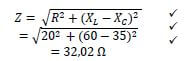 (3)
(3)
2.4.2 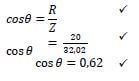 (3)
(3)
2.4.3 lagging ✔ (1)
2.4.4 The Q-factor will be halved ✔because the Q-factor is inversely proportional to the resistance of the circuit. ✔ The doubling of the inductance and capacitance as a ratio will have no effect on the Q-factor. ✔ (3)
2.5
2.5.1 (3)
(3)
2.5.2
I = V
R
= 100
120
= 0,83A (3)
2.5.3
I = V
R
=100
120
= 0,83A (3)
2.5.4
IC = V
XC
=100
220
= 0,455 A (3)
2.5.5  (3)
(3)
2.5.6 (3)
(3)
2.5.7 (4)
(4)
[40]
QUESTION 3: THREE-PHASE AC GENERATION (SPECIFIC)
3.1 The switchgear is used to interrupt or reconnect ✔ very high voltages and very high amounts of power ✔ (2)
3.2 (4)
(4)
3.3
3.3.1
- PT = W1 + W2
W2 = PT - W1
= 4 000 − 2 500 ✔
= 6 500 W or 6,5 kW ✔ (3)
3.3.2 To eliminate the need for precise mechanical components ✔and to reduce the need for calibration and adjustment ✔ (2)
3.4
- Installation costs are very high ✔
- Not available everywhere ✔
- Not suitable for residential areas
- Appliances are expensive (Any TWO) (2)
3.5.
- Static capacitors ✔
- Synchronous motors ✔
- Phase advancers ✔ (3)
3.6
3.6.1
- VPH = VL
= 250 V✔ (2)
3.6.2
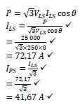
- S = √3VLIL
IL = S
√3VL
= 300 000
√3 × 250
= 692,82 (3)
3.6.3
- P= √3VLIL cos θ ✔ P = S cos θ ✔
= √3 × 250 × 692,82 × 0,866 ✔ = 300 000 × 0,866 ✔
= 259 799,88 W OR = 259 800 W
= 259,8 kW ✔ = 259,8 kW✔ (3)
3.6.4
- θ = cos−1 0,866 = 30° ✔ θ = cos−1 0,866 = 30° ✔
Q = √3VLIL sin θ ✔ Q = S sin θ ✔
= √3 × 250 × 692,82 × sin 30 ✔ OR = 300 000 × sin 30 ✔
= 149 999,93 VAr = 150 000 VAr
= 150 kVAr ✔ = 150 kVAr ✔ (4)
3.7 Efficiency is the ratio ✔of the input power to the output power. ✔ (2) [30]
QUESTION 4: THREE-PHASE TRANSFORMERS (SPECIFIC)
4.1
- Constant overloading ✔
- Insufficient ventilation ✔
- Insufficient transformer oil ✔
- Impure transformer oil (3)
4.2
4.2.1. No. ✔
- The frequencies are not identical ✔
- The voltages are not identical ✔ (3)
4.2.2. No. ✔
- The standard frequency in South Africa is 50 Hz ✔ (2)
4.2.3 The transformer would not operate. ✔ A direct current supply has a constant magnetic field and cannot create the contracting and expanding magnetic field ✔ required for induction to take place ✔ (3)
4.3
- Eddy current losses ✔
- Hysteresis losses ✔ (2)
4.4
- Star-star ✔
- Star-delta ✔
- Delta-star
- Delta-delta (2)
4.5 This could lead to excessive temperatures ✔ that could lead to serious problems like insulation failure ✔ (2)
4.6
4.6.1
- VPP = VLP ✔
= 11kV ✔ (2)
4.6.2
 (6)
(6)
4.6.3
- η = output × 100% ✔
output + losses
= 25 000 × 100% ✔
25 000+2 800
= 89,93% ✔ (3)
4.6.4
- Turns ratio = VPP:VPS ✔
= 11 000 ∶ 250
= 44 ∶ 1 ✔ (2)
[30]
QUESTION 5: THREE-PHASE AND STARTERS (SPECIFIC)
5.1
- Cheaper cost ✔
- Rugged in construction ✔
- Low maintenance
- No moving contacts in rotor
- Higher efficiency
- Can operate in any environmental condition (Any TWO) (2)
5.2
5.2.1 The tendency of a rotor to remain under the stator teeth (locking tendency) ✔ due to the direct magnetic attraction between the two ✔ (2)
5.2.2 By having a skewed rotor ✔ (1)
5.3
- NR = NS - S × NS ✔ OR NR = NS(1 - S)
= 3 600 − (0,045 × 3 600) ✔ = 3 600(1 − 0,045) ✔
= 3 438 rpm✔ = 3 438 rpm✔ (3)
5.4 Contactors are electromagnetically operated switches ✔ that provide a safe and convenient means for connecting and interrupting circuits ✔ (2)
5.5
5.5.1 Star-delta starter control circuit ✔ (1)
5.5.2
- A – overload(O/L) contact ✔
- B – MC3 (N/C) contact ✔ (2)
5.5.3
5.5.3.1 Prevents the other parts of the circuit from being energised before MC1 ✔ (1)
5.5.3.2 Interlocking contact to prevent MC3 contact being energised while motor is running in star ✔ (1)
5.5.3.3 Delays the current from flowing to MC3 for a pre-set time ✔ (1)
5.5.4
- MC1 is energised and all its contacts change state ✔
- The timer and MC2 are energised ✔
- The motor runs in star while the timer is timing ✔
- After the pre-set time, the timer contacts change state causing MC2 to be de-energised ✔
- MC3 is energised and the motor runs in delta ✔ (5)
5.6
5.6.1 (3)
(3)
5.6.2 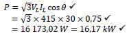 (3)
(3)
5.6.3 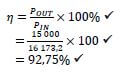 (3) [30]
QUESTION 6: PROGRAMMABLE LOGIC CONTROLLER (PLCs) (SPECIFIC)
6.1 A PLC is an industrial computer that is programmed to perform a number of routine tasks, ✔ in a strict order ✔ at exactly the right time ✔ (3)
6.2
- PLCs are relatively cheap when compared to bulky relays and their cabinets ✔
- Modifications are less expensive as programmes are altered instead of buying new devices ✔ (2)
6.3
6.3.1 NOT gate ✔ (1)
6.3.2
A | OUTPUT |
0 | 1 ✔ |
1 | 1 ✔ |
(2)
6.3.3 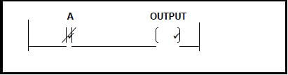 (2)
(2)
6.4
- Detecting and positioning objects ✔
- Measuring rotating speed ✔
- Counting objects on a conveyor ✔
- Detecting direction (Any THREE) (3)
6.5 A latch makes it possible for an event to be triggered on and remains on ✔ regardless of whether the activating trigger is on or off ✔ (2)
6.6
- Lifts ✔
- Cranes ✔
- Mine winding gear ✔
- Electrical locomotives
- Electrical vehicles (Any THREE) (3)
6.7
6.7.1
- Improves energy usage ✔
- Reduces motor wear ✔ (2)
6.7.2 The microprocessor controls the entire process by monitoring the incoming voltage supply, ✔ speed set-point, ✔DC limit voltage ✔ and output voltage and current ✔ to ensure operation of the motor is within the established parameters ✔ (5)
6.7.3 They have a mathematical model of the drive-in software ✔ and by measuring the current vectors in relation to the applied voltage, ✔ they are able to maintain a constant field at all frequencies below the line frequency ✔ (3)
6.7.4
- Three Phase ✔
- Diodes and label ✔
- Capacitor and label ✔
- Switches and label ✔
- Motor ✔ (5)
6.7.5
- Part 1: Consists of three pairs of rectifying diodes ✔ to convert the AC supply to a DC voltage ✔
- Part 2: Uses filter capacitors ✔ to smooth out the AC ripple ✔ Part 3: Inverts the DC voltage back to AC voltage at different frequencies ✔ by switching the Insulated Gate Bipolar Transistor on and off at a high frequency. ✔
The longer the switch is on, the longer the output waveform and the lower the frequency. ✔
The longer the switch is off, the shorter the output waveform and the higher the frequency ✔ (8)
6.8
6.8.1
- MC1 is energised, all its contacts change state ✔ and M1 starts running. ✔
- The timer is energised and starts to time the pre-set time. ✔
- After the pre-set time the timer contact closes. ✔
- MC2 is energised and M2 starts running ✔ (5)
6.8.2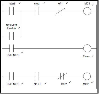 (11)
(11)
6.8.3 Current would stop flowing after the start button has been released, ✔ MC1 will de-energise ✔ and the sequence cannot be completed ✔ (3) [60]
TOTAL: 200
Electrical Technology: Power Systems Grade 12 Questions - NSC Exams Past Papers and Memos September 2019 Preparatory Examinations
INSTRUCTIONS AND INFORMATION
- This question paper consists of SIX questions.
- Sketches and diagrams must be large, neat and fully labelled.
- Show ALL calculations and round off answers correctly to TWO decimal places.
- Number the answers correctly according to the numbering system used in this question paper.
- You may use a non-programmable calculator.
- Show the units for ALL answers of calculations.
- A formula sheet is provided at the end of this question paper.
- Write neatly and legibly.
QUESTIONS
QUESTION 1: OCCUPATIONAL HEALTH AND SAFETY (GENERIC)
1.1 Name THREE unsafe conditions that cause most accidents in the workshop. (3)
1.2 Explain the purpose of the Occupational Health and Safety Act. (2)
1.3 Give TWO unsafe acts in a school workshop that can cause an accident. (2)
1.4 Describe THREE standard treatments for electric shock after the electricity has been removed. (3) [10]
QUESTION 2: RLC CIRCUITS (GENERIC)
2.1 Define the term Q-factor with reference to a parallel resonant circuit. (2)
2.2 State THREE factors that will affect the impedance of an RLC circuit. (3)
2.3 List THREE characteristics of a series resonance frequency. (3)
2.4 Refer to the circuit diagram FIGURE 2.4 below and answer the questions that follow.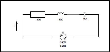
FIGURE 2.4: RLC CIRCUIT
Given:
R = 20 Ω
XL = 60 Ω
XC = 35 Ω
VS = 240 V
F = 50 Hz
2.4.1 Calculate the total impedance of the circuit. (3)
2.4.2 Calculate the power factor of the circuit. (3)
2.4.3 State whether the power factor is leading or lagging. (1)
2.4.4 Explain what happens to the Q-factor of an RLC circuit if the values of R, L and C are doubled. (3)
2.5 A parallel RLC circuit consists of a resistor with a resistance of 120 Ω, an inductor with an inductive reactance of 160 and a capacitor with a capacitive reactance of 220 Ω. All are connected across a 100 V / 50 Hz supply.
2.5.1 Draw the circuit diagram that represents the above information. (3) Calculate:
2.5.2 The current through the resistor (3)
2.5.3 The current through the inductor (3)
2.5.4 The current through the capacitor (3)
2.5.5 The total current of the circuit (3)
2.5.6 The phase angle (3)
2.5.7 Draw the phasor diagram that represents the current and the voltage. (4) [40]
QUESTION 3: THREE-PHASE AC GENERATION (SPECIFIC)
3.1 State the purpose of the switchgear used in substations. (2)
3.2 Draw a labelled phasor diagram of a balanced three-phase system. (4)
3.3 The following values were obtained by using the two-wattmeter method.
PT = 4kW
W1 = −2500 W
W2 = ?
3.3.1 Determine the reading of W2. (3)
3.3.2 Explain why digital electronics form the basis for meters used today. (2)
3.4 State TWO disadvantages of a three-phase system when compared to a single phase system. (2)
3.5 Mention THREE types of reactive elements introduced to improve a low power factor. (3)
3.6 A three-phase delta connected load is supplied by a 300 kVA generator with a line voltage of 250 V. The power factor is 0,866 lagging.
Given:
S = 300 kVA
VL = 250 V
cos θ = 0,866
Calculate:
3.6.1 The phase voltage (2)
3.6.2 The line current to the delta connected load (3)
3.6.3 The active power (3)
3.6.4 The reactive power (4)
3.7 Define efficiency of a three-phase system. (2) [30]
QUESTION 4: THREE-PHASE TRANSFORMERS (SPECIFIC)
4.1 List THREE factors that could lead to excessive heating in transformers. (3)
4.2 The table below represents the information available on three single-phase transformers. Study the table and answer the questions that follow.
CHARACTERISTICS | Transformer A | Transformer B | Transformer C |
Frequency | 50 Hz | 50 Hz | 60 Hz |
Voltage | 240 V – 24 V | 240 V – 24 V | 110 V – 24 V |
Current | 15 A | 15 A | 15 A |
Power | 360 VA | 360 VA | 360 VA |
4.2.1 State, with reasons, if the transformers are suitable to be connected as three-phase transformers. (3)
4.2.2 Determine if transformer C is suitable for operation on a standard South African supply. (2)
4.2.3 Explain what would happen if transformer A is connected to a 240 V direct current supply. (3)
4.3 Name TWO losses that occur in the iron cores of transformers. (2)
4.4 Write down TWO methods used when connecting three single-phase transformers to operate as a three-phase transformer. (2)
4.5 Explain what could happen if large transformers did not have cooling systems. (2)
4.6 A three-phase transformer with a primary line voltage of 11 kV is connected in delta-delta to a 25 kW load with a power factor of 0,8. The secondary line voltage is 250 V and the losses amount to 2,8 kW.
Given:
VLP = 11 kV
POUT = 25 kW
cos θ = 0,8
VLS = 250 V
Losses = 2,8 kW
Calculate:
4.6.1 The primary phase voltage (2)
4.6.2 The secondary phase current (6)
4.6.3 The efficiency (3)
4.6.4 The turns ratio (2) [30]
QUESTION 5: THREE-PHASE MOTORS AND STARTERS (SPECIFIC)
5.1 Give TWO reasons why squirrel cage motors are more widely used in industrial applications than slip ring induction motors. (2)
5.2 Answer the following with reference to the rotor of an induction motor:
5.2.1 Explain the term cogging of the rotor. (2)
5.2.2 State how cogging is overcome. (1)
5.3 Calculate the rotor speed of a squirrel cage rotor if the synchronous speed is 3 600 rpm and the slip is 4,5%.
Given:
S = 4,5%
NS = 3600 rpm (3)
5.4 State the purpose of contactors used in starter circuits. (2)
5.5 Refer to the control circuit in FIGURE 5.5 and answer the questions that follow.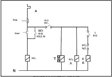
FIGURE 5.5 CONTROL CIRCUIT
5.5.1 Identify the control circuit in FIGURE 5.5. (1)
5.5.2 Supply labels to the contacts labelled A and B. (2)
5.5.3 Explain the functions of the following contacts:
5.5.3.1 MC1(N/O) hold in (1)
5.5.3.2 MC2(N/C) (1)
5.5.3.3 T(N/O) (1)
5.5.4 Explain what occurs when the circuit is energised and the start button is pressed. (5)
5.6 A 415 V three-phase motor is rated at 15 kW and has a power factor of 0,75. It draws a current of 30 A when connected in delta to the supply.
Given:
POUT = 15 kW
VL = 415 V
IL = 30 A
cos θ = 0,75
Calculate:
5.6.1 The phase voltage of the motor coils (3)
5.6.2 The input power to the motor (3)
5.6.3 The efficiency of the motor (3) [30]
QUESTION 6: PROGRAMMABLE LOGIC CONTROLLERS (PLCs) (SPECIFC)
6.1 Define a programmable logic controller (PLC). (3)
6.2 Discuss how cost is an advantage to a PLC when compared to hard wired relay systems. (2)
6.3 Refer to FIGURE 6.3 below and answer the questions that follow. 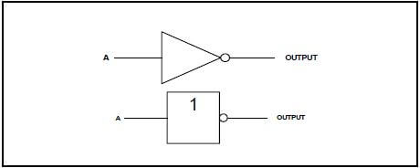
FIGURE 6.3
6.3.1 Identify the logic gate shown in FIGURE 6.3. (1)
6.3.2 Draw the truth table for the gate shown in FIGURE 6.3. (2)
6.3.3 Draw the ladder logic diagram. (2)
6.4 State THREE applications of proximity sensors. (3)
6.5 Describe in detail a latch in a circuit. (2)
6.6 List THREE applications of regenerative braking. (3)
6.7 Answer the following questions with reference to Variable Speed Drives (VSD):
6.7.1 State TWO advantages of using variable speed drives. (2)
6.7.2 Explain the function of the microprocessor. (5)
6.7.3 Describe how the vector drives perform their function. (3)
6.7.4 Draw a neat, labelled circuit diagram showing a VSD connected to a three-phase motor. (5)
6.7.5 Discuss in detail the THREE parts a VSD consists of. (8)
6.8 Refer to FIGURE 6.8 below and answer the questions that follow.
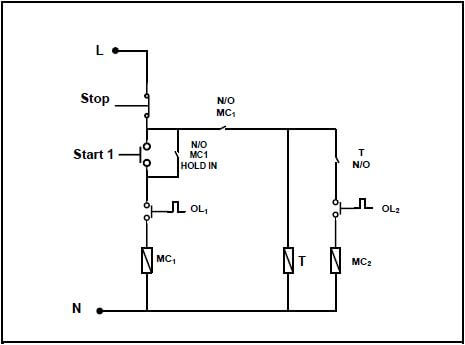
FIGURE 6.8
6.8.1 Describe the sequence after start 1 has been pressed. (5)
6.8.2 Draw the ladder diagram that executes the same function as the circuit diagram in FIGURE 6.8. (11)
6.8.3 Explain what would happen if N/O MC1 HOLD IN was not connected in the circuit. (3) [60]
TOTAL: 200
Electrical Technology: Electronics Grade 12 Memorandum - NSC Exams Past Papers and Memos September 2019 Preparatory Examinations
INSTRUCTIONS TO MARKERS
- All questions with multiple answers imply that any relevant, acceptable answer should be considered.
2. Calculations:
2.1 All calculations must show the formulae.
2.2 Substitution of values must be done correctly.
2.3 All answers MUST contain the correct unit to be considered.
2.4 Alternative methods must be considered, provided that the correct answer is obtained.
2.5 Where an incorrect answer could be carried over to the next step, the first answer will be deemed incorrect. However, should the incorrect answer be carried over correctly, the marker has to re-calculate the values, using the incorrect answer from the first calculation. If correctly used, the candidate should receive the full marks for subsequent calculations.
2.6 Markers should consider that candidates' answers may deviate slightly from the marking guideline depending on how and where in the calculation rounding off was used. - These marking guidelines are only a guide with model answers.
- Alternative interpretations must be considered and marked on merit. However, this principle should be applied consistently throughout the marking session at ALL marking centres.
MEMORANDUM
QUESTION 1: OCCUPATIONAL HEALTH AND SAFETY (GENERIC)
1.1
- Faulty tools or equipment ✓
- Poor ventilation ✓
- Poor quality of or missing guards on machines ✓
- Excessive noise
- Lack of knowledge of emergency procedures
(Any THREE relevant answers) (3)
1.2 The purpose of the Occupational Health and Safety Act is to provide for the health and safety of:
- Persons at work ✓
- Persons in connection with the use of plant and machinery ✓
- The protection of persons against hazards arising out of the activities of other persons at work
- To establish an advisory council for occupational health and safety and related matters (2)
1.3
- Horseplay ✓
- Running in the workshop ✓
- Throwing things around
- Leaving bags, stools/chairs or material in walkway
- Spilling a liquid or oil without cleaning
- (Any relevant answer) (2)
1.4
- Keep person lying down ✓
- Cover the person to maintain body heat ✓
- Do not move the person in case of neck or spine injuries ✓
- If unconscious, put them on their side (recovery position)
(Any THREE relevant answers) (3) [10]
QUESTION 2: RLC CIRCUITS (GENERIC)
2.1 Q-factor for a parallel circuit concerns the relationship between the resistance and the reactance of the circuit ✓
The Q-factor of the circuit is found from the ratio between the reactive components either the inductive or capacitance at resonance and the active power of the resistance ✓ (2)
2.2 Factors that affect the impedance of an RLC circuit:
- Frequency ✓
- Inductance ✓
- Capacitance ✓ (3)
2.3
- Z = R ✓
- XL = XC ✓
- Cos θ = 1 ✓
- R = minimum
- I = maximum (Any THREE) (3)
2.4
2.4.1 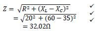 (3)
(3)
2.4.2 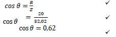 (3)
(3)
2.4.3 lagging ✓ (1)
2.4.4 The Q-factor will be halved ✓because the Q-factor is inversely proportional to the resistance of the circuit. ✓ The doubling of the inductance and capacitance as a ratio will have no effect on the Q factor ✓ (3)
2.5
2.5.1 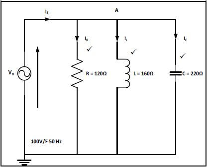 (3)
(3)
2.5.2
- I = V
R
=100
120
= 0,83A
2.5.3
- IL = V
XL
=100
160
= 0,625A
2.5.4
- IC = V
XC
=100
220
= 0,455A
2.5.5 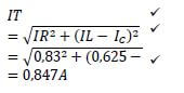
2.5.6
- cos θ =IR=
IZ
= cos-1 0,83
0,847
= 11,5° (3)
2.5.7 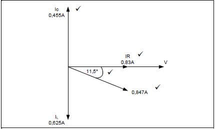 (4)
(4)
[40]
QUESTION 3: SEMICONDUCTOR DEVICES (SPECIFIC)
3.1 Junction field effect transistor (JFET) ✓and Metal oxide semiconductor (MOSFET) ✓ (2)
3.2
- The main advantage of a FET over A BJT is that it has significantly lower levels of power loss making it more efficient ✓
- FET’s also have high input resistance thus drawing very little current from the previous stage ✓ (2)
3.3
- A signal applied to the non-inverting terminal ✓will appear at the output terminal in the same direction as when it entered the op-amp ✓
- A signal applied to the inverting terminal will appear ✓ at the output terminal in an inverted direction as when it entered the op-amp ✓ (4)
3.4
- The mode of operation of a UJT is controlled by varying the value of Re which will change the amount of available current ✓
- A lower amount of current will not allow the UJT to saturate but rather force it to reset and re-trigger ✓ (2)
3.5
- Input stage (Differential amplifier) ✓
- Intermediate stage (High gain differential amplifier) ✓
- Common Collector (Darlington Pair) output stage ✓ (3)
3.6 The ability of the Op-amp to suppress a common-anode is called the common-mode rejection ratio ✓ (2)
3.7
3.7.1 Non-inverting Op-amp ✓ (1)
3.7.2
- AV = 1 + Rf
Rin
= 1 + 1000
1900 ✓
= 1 + 0,526
= 1,526 ✓ (2)
3.8
- Basic timing function, e.g. turning a light on or off after a period of time ✓
- Pulse oscillation and wave generation ✓
- Creating a flashing warning light ✓
- Digital logic probes
- Producing musical notes of specific frequencies
- Temperature measurement
- Controlling the positioning of servo devices (3)
3.9
- Only operate on supply voltages between +5V to + 18V ✓
- The maximum current it can either sink or source is 200 mA ✓ (2)
3.10
- In the construction of this IC there are three series connected resistors of identical value, 5 kΩ ✓
- These resistors divide the voltages to 2/3 ✓ and 1/3 ✓ of the supply voltage (3)
3.11 Threshold ✓ (1)
3.12
- This pin sets off the IC
- It is an active low trigger ✓
- When the voltage on pin 2 is less than 13of the supply, the output goes high ✓
- When the voltage on pin 2 is higher than 23of the supply, the output will go low ✓
- If connected to ground the output will go ‘high’ and remain ‘high’ (3) [30]
QUESTION 4: SWITCHING CIRCUITS (SPECIFIC)
4.1
4.1.1 Mono-stable multivibrator ✓ (1)
4.1.2
- It has ONE input ✓
- It has ONE stable state ✓ (2)
4.1.3
- The RC network in this circuit is the timing component of this circuit ✓
- The values of the resistor and the capacitor determine for how long the circuit will be in the HIGH ✓state before it reverts back to its stable LOW state ✓ (3)
4.1.4
- By changing R2 from a fixed resistor value to a variable resistor ✓
- By changing the value of C2 from a fixed value capacitor to a variable capacitor ✓
- By changing both R2 and C2 from fixed values ✓ to variable values ✓ (4)
4.1.5
- When the circuit is in resting condition, the negative voltage of -Vref on the inverting input serves to hold this inverting input low ✓
- This will cause the Op-Amp to saturate and the output to rise to and stay at +15 V ✓
- The capacitor, C, charges up with the top plate to + 15 V, and the bottom plate to 0 V ✓
- When the capacitor is charged, no current flows through R as there is no voltage over it. This holds the non-inverting input at 0 V ✓
- A positive trigger pulse larger than Vref applied to the inverting input terminal will raise the inverting input potential above the 0 V of the non-inverting input ✓
- The Op-Amp will now saturate and the output will go to -15 V ✓
- The capacitor will now immediately start discharging through the resistor Rf✓
- The lower plate of the capacitor rises to 0 V and when the voltage is less negative than Vref, the output changes to +15 V again ✓ (8)
4.1.6 Debouncing ✓ (1)
4.2 4.2.1 At one end the potentiometer will be connected to 0 Ω. ✓ R1 will prevent the full supply flowing to pin 6 and 7, when the potentiometer is in the 0 Ω position ✓ (2)
4.2.2
- By changing the value of C1 ✓
- By changing the value of R3 ✓ (2)
4.2.3 The time period will increase ✓ (1)
4.3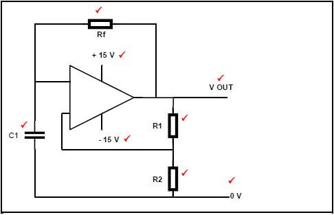 (8)
(8)
4.4 (6)
(6)
4.5 The time lag (delay) between cause ✓ and effect ✓ (2)
4.6
- First stage of many radio receivers to clean up noise ✓
- To eliminate switch bounce in digital circuits ✓
- Varying input waveforms, for instance sine wave changed into square wave or rectangular wave
- Signal recovery after experiencing severe distortion (2)
4.7 (8)
(8)
4.8 (6)
(6)
4.9 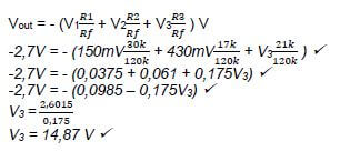
(4) [60]
QUESTION 5: AMPLIFIERS (SPECIFIC)
5.1 Class B amplification is when the output collector current of the amplifier ✓ only flows for the input cycle ✓ (2)
5.2
5.2.1
- VCC =VCE + ICRC ✓
VCC = VCE ✓✓when the transistor is OFF and collector current is not flowing
VCE = 9 v ✓ (4)
5.2.2
- IC = VC
RC
=9
750√
= 12 mA√ (3)
5.2.3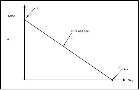
(3)
5.3
- RF communications ✓
- Optical fibre communications ✓
- Pre-amplifiers in public address systems ✓
- Small signal amplifiers in radio or TV receivers (3)
5.4
- Improving the amplifier’s stability ✓
- Increasing the amplifier’s bandwidth ✓
- Enhancing the amplifier’s input and output impedances ✓
- Reducing or suppressing a noise produced with the amplifier (3)
5.5
- Low frequency area ✓
- Middle frequency area ✓
- High frequency area (2)
5.6
5.6.1
- AV = 20Log10EOUT√
EIN
AV = 20Log106.2√
4
AV = 20 × 1.55
AV = 31 dB √ (3)
5.6.2
- Ap = 10 log10Pout
Pin√
Ap = 10log10 29
850×10−3 √
Ap = 341.2dB √ (3)
5.7
- Class AB ✓
- Class AB does not allow a transistor to move into its cut-off region, ✓ so it eliminates the distortion ✓ (3)
5.8 Radio frequency amplifiers are designed to amplify ✓ a single high frequency ✓ (2)
5.9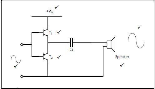 (6)
(6)
5.10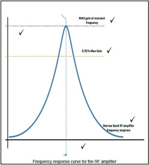 (6)
(6)
5.11
5.11.1 Positive feedback ✓ (1)
5.11.2 RC phase shift oscillator is widely used in the lower audio frequency AF range up to 10 kHz ✓ (1)
5.12
5.12.1 RF coil offers resistance against the change in the collector current ✓ and causes the collector voltage Vc to decrease ✓ (2)
5.12.2 The tank circuit receives energy from a DC source ✓and converts that energy into a sinusoidal signal at a frequency determined by the inductor and capacitor ✓ (2)
5.12.3
- Hartley oscillator tank circuit consists of two inductors and one capacitor ✓
- Colpitts oscillator tank circuit consists of two capacitors and one inductor ✓ (2)
5.13
- Poor frequency response. Gain is constant over only a small range of frequencies ✓
- Increased cost ✓
- Tends to introduce hum in the output ✓
- Low frequency receives less amplification than high frequencies ✓ (4)
5.14
- They isolate each stage by blocking the DC voltage of one stage ✓ from affecting the next. ✓ They allow AC signals to pass freely from one stage to the next ✓ (3)
5.15
- Resistance capacitance coupling ✓
- Transformer coupling ✓ (2) [60]
TOTAL: 200
Electrical Technology: Electronics Grade 12 Questions - NSC Exams Past Papers and Memos September 2019 Preparatory Examinations
INSTRUCTIONS AND INFORMATION
- This question paper consists of FIVE questions.
- Sketches and diagrams must be large, neat and fully labelled.
- Show ALL calculations and round off answers to TWO decimal places. Show the units for ALL answers of calculations.
- Number the answers correctly according to the numbering system used in this question paper.
- You may use a non-programmable calculator.
- A formula sheet is provided at the end of this question paper.
- Write neatly and legibly.
QUESTIONS
QUESTION 1: OCCUPATIONAL HEALTH AND SAFETY (GENERIC)
1.1 Name THREE unsafe conditions that cause most accidents in the workshop. (3)
1.2 Explain the purpose of the Occupational Health and Safety Act. (2)
1.3 Give TWO unsafe acts in a school workshop that can cause an accident. (2)
1.4 Describe THREE standard treatments for electric shock after the electricity has been removed. (3) [10]
QUESTION 2: RLC CIRCUITS (GENERIC)
2.1 Define the term Q-factor with reference to a parallel resonant circuit. (2)
2.2 State THREE factors that will affect the impedance of an RLC circuit. (3)
2.3 List THREE characteristics of a series resonance frequency. (3)
2.4 Refer to FIGURE 2.4 below and answer the questions that follow.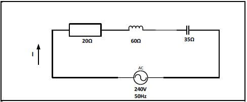
FIGURE 2.4: RLC CIRCUIT
Given:
R = 20 Ω
XL = 60 Ω
XC = 35 Ω
VS = 240 V
F = 50 Hz
2.4.1 Calculate the total impedance of the circuit. (3)
2.4.2 Calculate the power factor of the circuit. (3)
2.4.3 State whether the power factor is leading or lagging (1)
2.4.4 Explain what happens to the Q-factor of an RLC circuit if the values of R, L and C are doubled. (3)
2.5 A parallel RLC circuit consists of a resistor with a resistance of 120 Ω, an inductor with an inductive reactance of 160 Ω and a capacitor with a capacitive reactance of 220 Ω. All are connected across a 100 V/50 Hz supply.
2.5.1 Draw the circuit diagram that represents the above information. (3) Calculate:
2.5.2 The current through the resistor (3)
2.5.3 The current through the inductor (3)
2.5.4 The current through the capacitor (3)
2.5.5 The total current of the circuit (3)
2.5.6 The phase angle (3)
2.5.7 Draw the phasor diagram that represents the current and the voltage. (4) [40]
QUESTION 3: SEMI-CONDUCTOR DEVICES (SPECIFIC)
3.1 List TWO types of field effect transistors. (2)
3.2 State the main advantage of a field effect transistor over a bipolar-junction transistor. (2)
3.3 Describe the difference between the inverting and the non-inverting amplifier of an Op-Amplifier. (4)
3.4 Explain how it is possible to control the mode of operation of a UJT. (2)
3.5 State the THREE stages of a 741 Op-Amp. (3)
3.6 Explain the term Common Mode Rejection Ratio. (2)
3.7 Refer to FIGURE 3.7 below and answer the questions that follow. 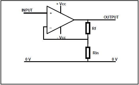
FIGURE 3.7: OP-AMPLIFIER
3.7.1 Identify the Op-Amplifier in FIGURE 3.7 (1)
3.7.2 Calculate the gain of the amplifier if the feedback resistor has a value of 1 kΩ and the input resistor has a value of 1 900 Ω. (2)
3.8 Name THREE uses for the 555 timer IC. (3)
3.9 Name TWO operating boundaries of a 555 timer IC. (2)
3.10 Explain the purpose of the three internally connected series resistors in a 555 IC. (3)
3.11 Refer to FIGURE 3.11 below. Label pin 6. (1)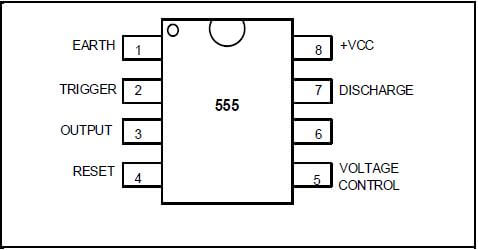
FIGURE 3.11: 555 TIMER
3.12 With reference to a 555 timer IC, explain the function of pin 2 (trigger). (3) [30]
QUESTION 4: SWITCHING CIRCUITS (SPECIFIC)
4.1 Refer to FIGURE 4.1 below and answer the questions that follow.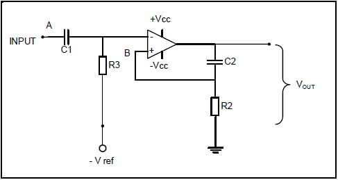
FIGURE 4.1: MULTIVIBRATOR
4.1.1 Identify the multivibrator in FIGURE 4.1. (1)
4.1.2 Name TWO characteristics of this multivibrator. (2)
4.1.3 Explain the function of the network C2 and R2. (3)
4.1.4 Analyse FIGURE 4.1 above and explain the THREE ways to change this circuit in order to have a variable time in the high state. (4)
4.1.5 Explain the principle of operation of the circuit in FIGURE 4.1. (8)
4.1.6 With reference to FIGURE 4.1, name ONE application of this multivibrator. (1)
4.2 Refer to FIGURE 4.2 above and answer the questions that follow. 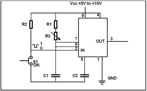
FIGURE 4.2: MULTIVIBRATOR
4.2.1 Explain the function of R1 in the circuit. (2)
4.2.2 Name TWO methods to vary the time period of this circuit. (2)
4.2.3 Explain the effect on the output waveform if R3 is changed from 10 kΩ to 27 kΩ. (1)
4.3 Draw a fully labelled circuit diagram of an Op-Amp Astable multivibrator circuit. (8)
4.4 With reference to the Schmitt trigger, draw a fully labelled hysteresis characteristic curve (6)
4.5 Define the term hysteresis with reference to the Schmitt trigger. (2)
4.6 Name TWO applications of the Schmitt trigger. (2)
4.7 Draw a fully labelled circuit diagram of a temperature sensor circuit. (8)
4.8 Draw a fully labelled circuit diagram of a summing amplifier with THREE inputs. (6)
4.9 A summing amplifier has three input resistors with the following values:
R1 = 30 kΩ, R2 = 17 kΩ, R3 = 21 kΩ
The output voltage for this circuit is given as -2,7 V.
The known input voltages are V1 = 150 mV, V2 = 430 mV.
Calculate the value of V3 if this circuit has a 120 kΩ feedback resistor. (4) [60]
QUESTION 5: AMPLIFIERS (SPECIFIC)
5.1 Explain Class B amplification with reference to the output collector. (2)
5.2 Refer to FIGURE 5.2 below and answer the questions that follow.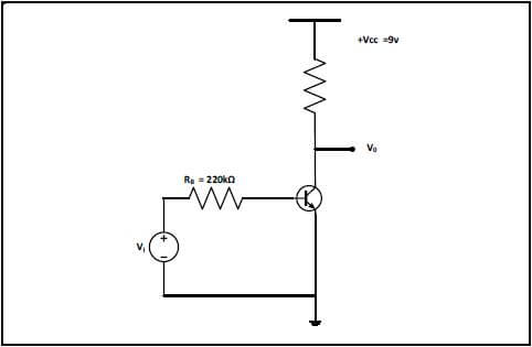
FIGURE 5.2: CLASS A FIXED BIASED TRANSISTOR AMPLIFER
5.2.1 Calculate the maximum collector voltage. (4)
5.2.2 Calculate the maximum collector current. (3)
5.2.3 Draw the circuit load line of the circuit. (3)
5.3 State THREE applications of an RC coupled amplifier. (3)
5.4 List THREE advantages of negative feedback. (3)
5.5 Describe TWO important areas on the frequency curve. (2)
5.6 Use the given information to answer the following questions:
5.6.1 Calculate the voltage gain, if the voltage measured across the input terminals of an amplifier is 4 V and 6,2 V at the output terminals. (3)
5.6.2 An 850 mW signal is introduced to the input of an amplifier. On emerging the signal has been amplified to 29 W. Calculate the amplifier gain. (3)
5.7 Name the circuit used to eliminate the effects of cross-over distortion and explain how it is able to do this. (3)
5.8 Explain the purpose of a Radio frequency amplifier. (2)
5.9 Draw a fully labelled circuit diagram of a push-pull amplifier. (6)
5.10 Draw a fully labelled frequency response curve for the RF amplifier. (6)
5.11 Refer to FIGURE 5.11 below and answer the questions that follow.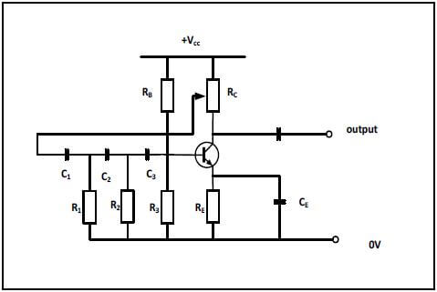
FIGURE 5.11: RC PHASE SHIFT OSCILLATOR
5.11.1 Name the type of feedback used in the above circuit diagram. (1)
5.11.2 State ONE application of the RC phase shift oscillator. (1)
5.12 FIGURE 5.12 refers to the Hartley oscillator. Answer the following questions. RF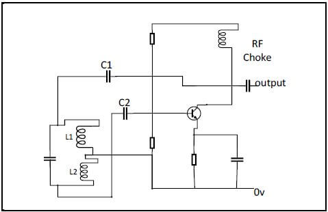
FIGURE 5.12: HARTLEY OSCILLATOR
5.12.1 Describe the function of the RF coil in the Hartley oscillator circuit. (2)
5.12.2 Discuss the purpose of the tank circuit in Hartley oscillators. (2)
5.12.3 Describe the difference between the Hartley oscillator and the Colpitts oscillator with reference to their tanks. (2)
5.13 List FOUR disadvantages of transformer coupling in amplifiers. (4)
5.14 Explain why DC blocking capacitors are used at the input and output of an amplifier. (3)
5.15 State TWO methods of inter-stage coupling. (2) [60]
TOTAL: 200
Mathematical Literacy P2 Grade 12 Addendum - NSC Exams Past Papers and Memos September 2019 Preparatory Examinations
ADDENDUM
ANNEXURE A: QUESTION 1.1
TABLE 1 – Account Statement for the duration of the loan period NOTE: (…) Some months and values have been omitted
| Conditions of Loan | Loan Amount | R750 000 | Interest rate (per annum) | 9,75% | |
| Interest rate (per month) | 0,8125% | ||||
| Loan Period | 30 years | ||||
Month | Opening Balance | Interest | Balance with interest | Repayment | Closing Balance |
1 | R750 000 | R6 093,75 | R756 093,75 | R6 442,50 | R749 651,25 |
2 | R749 651,25 | R6 090,92 | R755 742,17 | R6 442,50 | R749 299,67 |
3 | R749 299,39 | R6 088,06 | … | R6 442,50 | ... |
… | … | … | … | ... | |
60 | R722 033,45 | R5 866,52 | R727 899,97 | R6 442,50 | R721 457,47 |
… | … | … | … | ... | |
120 | R674 894,02 | R5 483,51 | R680 377,53 | R6 442,50 | R673 935,03 |
… | … | … | … | ... | |
300 | R286 424,55 | R2 327,20 | R288 751,75 | R6 442,50 | R283 309,25 |
… | … | … | … | ... | ... |
ANNEXURE B: QUESTION 1.3 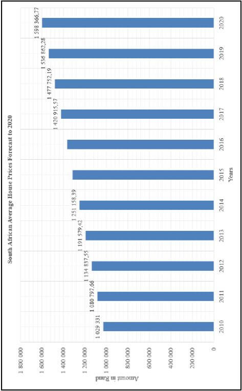
[Adapted from https://hous>
ANNEXURE C: QUESTION 2.1
Tax Table 2018/2019
Taxable Income (R) | Rates of tax (R) |
0–195 850 | 18% of taxable income |
195 851–305 850 | 35 253 + 26% of taxable income above 195 850 |
305 851–423 300 | 63 853 + 31% of taxable income above 305 850 |
423 301–555 600 | 100 263 + 36% of taxable income above 423 300 |
555 601–708 310 | 147 891 + 39% of taxable income above 555 600 |
708 311–1 500 000 | 207 448 + 41% of taxable income above 708 310 |
Tax Rebate 2018/2019 | |
Primary (younger than 65) | R13 635 |
Secondary (65 and older) | R7 479 |
Tertiary (75 and older) | R2 493 |
Tax Thresholds | |
Person | 2018/2019 |
Younger than 65 | R75 750 |
65 and older | R117 300 |
75 and older | R131 150 |
Medical aid credits 2018/2019 year of assessment |
R310 per month for the taxpayer who paid the medical scheme contributions |
R310 per month for the first dependant |
R209 per month for each additional dependant(s) |
ANNEXURE D: QUESTION 4.1 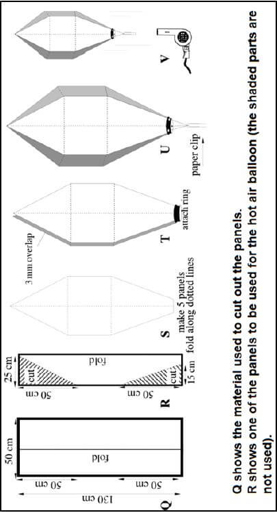
[Source: http://crammed-hot-air-balloon-construction-charle-s-la>
QUESTION 4.2 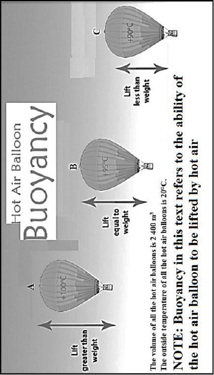
Mathematical Literacy P1 Grade 12 Addendum - NSC Exams Past Papers and Memos September 2019 Preparatory Examinations
ADDENDUM
ANNEXURE A: QUESTION 1.3
PICTURE OF 800 g BROWN BREAD | |||||||||||||||||||||||||||||||||
| |||||||||||||||||||||||||||||||||
kJ – kilojoule kcal – kilocalorie | |||||||||||||||||||||||||||||||||
| |||||||||||||||||||||||||||||||||

ANNEXURE B: QUESTION 2.4
HIRE PURCHASE AGREEMENT | |||
ACCOUNT NUMBER; 2019/7/0034/801 DATE OF PURCHASE: 1/07/2019 | |||
COST OF CREDIT | |||
TOTAL GOODS VALUE 86'' UHD Digital TV | R49 999,99 | TOTAL DEFERRED AMOUNT BROUGHT FORWARD | R46 875,00 |
Less deposit (10% of the goods value) | ------------- | Add interest for 24 months at 10,75% per annum on deferred amount | R10 078,13 |
Less discount | R0,00 | TOTAL DEFERRED AMOUNT | R56 953,13 |
ADD ADDITIONAL CHARGES SUBJECT TO INTEREST | ADD ADDITIONAL CHARGES NOT SUBJECT TO INTEREST | ||
*Extended guarantee | R1 000 | *Insurance | R14 400 |
*Delivery charges | R500 | Total cost of credit | R71 353,13 |
*Initiation fee | R375 | Add back deposit | ------------ |
TOTAL DEFERRED AMOUNT CARRIED FORWARD | R46 875,00 | CONTRACT TOTAL | R76 353,12 |
Items marked with asterisk (*) are inclusive of Value Added Tax-VAT 15%) | |||
INSTALMENT PAYMENT Total cost of credit is payable in 23 monthly instalments of R2 973,04 commencing on 1/8/2019 and the final instalment payment of R2 973,21. | |||
ANNEXURE C: QUESTION 4 
[Adapted from simataigreatwall.org]
Mathematical Literacy P2 Grade 12 Memorandum - NSC Exams Past Papers and Memos September 2019 Preparatory Examinations
Symbol | Explanation |
M | Method |
M/A | Method with accuracy |
MCA | Method with consistent accuracy |
CA | Consistent accuracy |
A | Accuracy |
C | Conversion |
S | Simplification |
RT/RG/RM | Reading from a table OR Reading from a graph OR Read from map |
F | Choosing the correct formula |
SF | Substitution in a formula |
J | Justification |
P | Penalty, e.g. for no units, incorrect rounding off etc. |
R | Rounding Off OR Reason |
AO | Answer only |
NPR | No penalty for rounding |
MARKING GUIDELINES
NOTE:
- If a candidate answers a question TWICE, only mark the FIRST attempt. ∙ If a candidate has crossed out (cancelled) an attempt to a question and NOT redone the solution, mark the crossed out (cancelled version)
- Consistent accuracy (CA) applies in ALL aspects of the marking guidelines, however it stops at the second calculation error.
- If the candidate presents any extra solution when reading from a graph, table, layout plan and map, then penalise for every extra incorrect item presented.
QUESTION 1 [37] | |||
Ques. | Solution | Explanation | Topic & Level |
1.1.1 | Interest Amount = R749 299,39 × 0,8125% ✔ A ✔RT✔ M OR Interest Amount = R749 299,39 × 0,008125 ✔A ✔RT ✔ M | 1RT Correct opening balance | L2 |
1.1.2 | Monthly repayment = 750 000 × 8,59 ✔RT OR Monthly repayment = 750 000 × 8,59 ✔RT ✔RT | 1RT Home loan | L2 |
1.1.3 | Closing balance for Month 3 ✔A = R749 299,39 + R6 088,06 – R6 442,50 ✔A = R748 944,95 | 1A Add and Subtract | L2 F |
1.1.4 | Statement not valid ✔R✔R The shorter the loan period, the higher the loan factor ✔R ✔R No ✔A ✔R ✔R | 1A Not valid | L4 F |
1.1.5 | Amount at 119 months = R6 442,50 × 119 ✔CA | 1MA Multiplying correct values | L4 F |
1.1.6 | It will reduce the interest amount. | 2A Explanation (2) | L4 F |
1.2.1 | Volume = 2 m × 2 m × 0,3 m ✔C | 1SF Substitution | M L2 |
1.2.2 | Bags of cement = 1,2 ✔M OR 0,26 = 2 bags ✔M ✔M | CA from 1.2.1 1M Ratio concept 1M Multiply by 2 | M L3 |
1.2.3 | Litres of paint needed = 15 × 1,08 OR Litres of paint needed = 15 × 108% | 1MA Increased surface area 1CA Total number of litres 1MA Increased surface area | M L3 |
1.3.1 | Price for 2015 = 1 251 158,39 + (1 251 158,39 × 0,05) ✔MA Price for 2016 = 1 313 716,31 + (1 313 716,31 × 0,04) OR Price from 2015 – 2016 = 1 251 158,39 × 1,05 × 1,04 ✔M ✔M✔S | 1MA Increase by 5% | L3 F |
1.3.2 | ✔RG | 1RG Subtract correct values | L3 F |
[39] |
QUESTION 2 [36] | |||
Ques. | Solution | Explanation | Topic and Level |
2.1.1 | Taxable Income = Gross Annual salary – Pension | 1M Subtract 7,5% | L2 F |
2.1.2 | Annual Tax ✔A | CA from 2.1.1 | L4 F |
2.2.1 | Probability other than African = 8,8% + 9,5% + 2,4% OR Probability other than African = 100% – 79,3% ✔M | 1MA Adding correct values | L2 P |
2.2.2 | African % = 100% – 8,8% – 9,5% – 2,4% ✔MA OR 37 001 380 African Population in 1911 = 67,3% × 5 972 757 ✔CA | 1MA Subtract from 100 | L3 D |
2.2.3 | 1911 = 0,08 × 5 972 757 ✔CA | 1MA % for 1911 | L2 D |
2.2.4 | Percentage of the African race group increased | 1A African increase | L4 |
2.3.1 | Number of people = (25 × 2) + 17 | 1MA × 2 and addition | L2 D |
2.3.2 | Cost for Option 1 = 1 500 + (250 × 67) | CA from 2.3.1 | L4 F |
[36] |
QUESTION 3 [39] | |||
Ques. | Solution | Explanation | Topic and Level |
3.1.1 | North West OR West of North ✔✔A | 2A Direction (2) | M&PL2 |
3.1.2 | Scale: 3,8 cm = 20 miles ✔A | 1A Measure scale | M&PL3 |
3.1.3 | 3,8 cm = 20 miles | CA from 3.1.2 | M L3 |
3.1.4 | Noise pollution OR Air pollution ✔✔R OR Danger ✔✔R OR Length of runways ✔✔R | 2R Reason (2) | M&PL4 |
3.1.5 | A 61 | 2A Road (2) | M&PL2 |
3.1.6 | Distance = Speed × Time OR Time = Distance ✔M | 1SF Substitution | M L4 |
3.2.1 | Range = Highest – Lowest | 1M Concept of range | D L2 |
3.2.2 (a) Mistakes: | 1A Mistake 1 | D L3 | |
3.2.2 (b) Correction: ✔M | 1M Arrange data ascending or descending | D L3 | |
3.2.3 | June, July and August ✔A | 1A Correct months | D L4 |
3.2.4 | Probability = 5 ✔A | CA from 3.2.1 | P L2 |
3.2.5 |  | CA from 3.2.1 | D L2 |
[39] |
QUESTION 4 [38] | |||
Ques. | Solution | Explanation | Topic and Level |
4.1.1 | Area of unshaded part OR Area of rectangle = Length × Width | 1SF Correct values for rectangle OR 1SF Correct values for rectangle | M L3 |
4.1.2 | To glue the seams together OR To paste sides together✔✔R | 2R Reason (2) | M L4 |
4.1.3 | Diagram T – A ring should be attached to the wide side of the ✔A hot air balloon | 1A Explain | M&P L2 |
4.1.4 | To blow hot air in balloon | 2R Reason (2) | M&P L4 |
4.2.1 | When the temperature increases, the lift of the hot air balloon is higher. ✔✔A ✔✔A OR When the temperature decreases, the lift of the hot air balloon is lower. ✔✔A ✔✔A | 2A Temperature increases | M&P L4 |
4.2.2 | Air Density of Hot air balloon B = 0,972+0,946 | 1MA Concept of average | M L4 |
4.2.3 | Probability = 33+12 ✔A | 1A Numerator | P L2 |
4.3 | Accommodation = 1 030 × 4 nights × 4 people ✔A | 1A 4 nights × 4 | F L3 |
[39] | |||
TOTAL: | 150 | ||