ELECTRICAL TECHNOLOGY GRADE 12 MEMORANDUM - NSC PAST PAPERS AND MEMOS FEBRUARY/MARCH 2018
Share via Whatsapp Join our WhatsApp Group Join our Telegram GroupELECTRICAL TECHNOLOGY
GRADE 12
NSC PAST PAPERS AND MEMOS
FEBRUARY/MARCH 2018
INSTRUCTIONS TO THE MARKERS
- All questions with multiple answers imply that any relevant, acceptable answer should be considered.
- Calculations
2.1 All calculations must show the formulae.
2.2 Substitution of values must be done correctly.
2.3 All answers MUST contain the correct unit to be considered.
2.4 Alternative methods must be considered, provided that the correct answer is obtained.
2.5 Where an incorrect answer could be carried over to the next step, the first answer will be deemed incorrect. However, should the incorrect answer be carried over correctly, the marker has to re calculate the values, using the incorrect answer from the first calculation. If correctly used, the candidate should receive the full marks for subsequent calculations. - This memorandum is only a guide with model answers. Alternative interpretations must be considered and marked on merit. However, this principle should be applied consistently throughout the marking session at ALL marking centres.
MEMORANDUM
QUESTION 1: OCCUPATIONAL HEALTH AND SAFETY
1.1
- Exposed conductors. ✔
- Portable electric equipment that is not insulated correctly. No safety equipment or clothing found in the workshop. (1)
1.2 The employer ✔is responsible for ensuring a safe working environment for workers and all visitors, due to the requirements of the OHS Act. ✔ (2)
1.3 Human rights relate to the correct and acceptable manner✔ in which all people are entitled to be treated in the workplace. ✔ (2)
1.4 The use of drugs impairs a workers perception✔ and reaction time✔, thus rendering such a worker vulnerable to the risk of injury and accidents. This situation may also place other workers at risk. (2)
1.5 To identify potential danger to employees and the public✔ from natural and human-caused events✔, thereby reducing the risk of accidents and loss✔ (3) [10]
QUESTION 2: THREE-PHASE AC GENERATION
2.1
2.1.1 Three-wattmeter-method ✔ of measuring power in an unbalanced three phase system. (1)
2.1.2
- A wattmeter has a voltage coil connected in parallel to measure / sample the voltage✔ across the load.
The current coil measures / samples the current flow through✔ the load.
The wattmeter combines✔ both the voltage and current readings (P=V x I) to determine the power in a circuit. (3)
2.2
- Two voltages are available, i.e. VL and VPh ✔
Three phase supply can be connected in star or delta✔
The load can be distributed over three phases, resulting in less current drawn per phase. (2)
2.3 It provides the owner with the consumption of electricity✔ that the dwelling has used over a period of time. ✔ (2)
2.4
- P = P1 + P2
= 2500 + 500 ✔
= 3 kW ✔ (3)
2.5
2.5.1
- P = √3 × VL × IL × Cosθ
VL = 11000
√3 × 25 × 0,8
= 317,54 V ✓ (3)
2.5.2
- IL = IPH
= 25 A ✓ (2)
2.6
- Three conductive coils are placed 1200apart in a magnetic field. ✓
- These coils are rotated through the magnetic field, resulting in the coils cutting the flux lines of the magnetic field. ✓
- Due to Faraday’s law✓ three separate alternating voltages are induced across the coil.(Oersted’s Experiment)
- The generated alternating voltages are 1200out of phase✓ with each other due to the physical displacement thereof. (4) [20]
QUESTION 3: THREE-PHASE TRANSFORMERS
3.1
- When an alternating voltage is applied to the primary winding, an alternating magnetic flux is set up in the core ✔
- The core concentrates the flux, coupling it with the secondary windings. ✓ An alternating EMF, of the same frequency as the supply, is induced across each winding. ✔
- When a load is connected to the secondary winding, current will flow as a result of the circuit being completed.✓
- Power is therefore transferred magnetically from the primary to the secondary windings✔ (5)
3.2
- Oil cooling✔
- Air cooling ✔
- Water-cooled oil cooling ✔ (3)
3.3 Copper losses are caused by the internal resistance✔ of the primary and secondary windings of the transformers. ✔ (2)
3.4
3.4.1
- NP = 1500
NS 50
= 30
1
TR = 30 : 1 ✔ (3)
3.4.2
- VL = VPH
= 3,3 kV ✔ (2)
3.4.3
- VPH(P) = NP
VPH(S) NS
VPH(S) = 50 × 3300
1500
= 100V ✔ (3)
3.4.4 The transformer is a step down transformer✔ because the V(PH)P is greater than V(PH) S✔ (2) [20]
QUESTION 4: THREE-PHASE MOTORS AND STARTERS
4.1
4.1.1
- It requires less maintenance as it does not have as many moving parts as a single phase motor.✔
- For the same size frame, a three-phase motor delivers higher torque. ✔ (2)
4.1.2 The connection to any TWO ✔of the windings must be swapped around. ✔ (2)
4.1.3
- A three-phase voltage supply is connected across the stator windings. ✔
- This sets up three-phase currents flowing in the stator windings. ✔
- The currents create a rotating magnetic field in the stator. ✔
- The rotating magnetic field sweeps across the rotor conductors. ✔
- This action induces an emf across the conductors in the rotor, which results in currents flowing in the conductors✔
- The induced rotor current in turn creates a magnetic field around the rotor. ✔
- The two magnetic fields interact causing the rotor to rotate. ✔ (7)
4.2 By doing a mechanical inspection the operator of a motor could prevent ✔ any mechanical or electrical failure that causes damage to the motor or injury to the operator. ✔ (2)
4.3 If the frequency of the supply increases the speed of the motor will increase,✔ because the speed of the motor is directly proportional to the frequency of the supply. ✔ (2)
4.4 The insulation test between the windings will give an indication whether insulation of the windings is intact or if the insulation has broken down ✔This could lead to a compromise of the safe use of the motor. ✔ (2)
4.5
- Check for secure mountings. ✔
- Check for cracked frame.
- Check smooth rotation (1)
4.6
4.6.1
- P = √3 VLILcosθ
= √3 × 380 × 5 × 0,8
= 4,739 kW ✔ (3)
4.6.2
- η = POUT × 100
P100%
= 4000 × 100
4739
= 84,4% (3)
4.7
4.7.1
- The start button must be depressed✔
- Thereafter MC1 is energised, and this will close MC1 N/O2 ✔ (2)
4.7.2 The function of the timer is to create a set time delay✔ between the starting of M1 and M2.✔ (2)
4.7.3 The current ratings of each motor. ✔ (1)
4.7.4
- The start button is pressed MC1N/O1 hold in and MC1 N/O2 close.✔
- The coil of MC1 is energised switching M1 on. ✔
- The timer is also energised.✔
- The T N/O begins a pre-set count.✔
- Once timed through MC2 coil is energised switching M2 on. ✔ (5)
4.8
- At start the stator of the motor will be connected in the star mode.✔
- When connected in star, the voltage across each phase is divided by √3.✔
- This in turn will divide the starting current by √3.✔ (3)
4.9
- A contactor consists of a coil✔
- and N/O or N/C contacts.✔
- When the coil is energised these contacts will switch into the opposite state due to electromagnetic actuation of the contacts. ✔
- By applying power to a contactor a secondary circuit/circuits may be activated/deactivated (3) [40]
QUESTION 5: RLC
5.1
5.1.1
- C = 1
2 × π × f × Xc
= 1
2 × π × 50 × 27
= 117,89 μF ✔ (3)
5.1.2
- The current flow would increase through the capacitor.✔
- If the frequency of the supply is increased the capacitive reactance will decrease✔ as it is indirectly proportional to the frequency of the supply. ✔ (3)
5.2 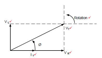 (5)
(5)
5.3
5.3.1
- XL = VT
IL
=240
6
= 40 Ω ✔ (3)
5.3.2
- XL = 2 × π × f × L
L = XL
2 × π × f
= 40
2 × π × f
= 127,32mH ✔(3)
5.3.3
- IT = √IR2 + IL2
= √72 + 62
= 9,22A ✔ (3) [20]
QUESTION 6: LOGIC
6.1
- Power supply✔
- Input and output devices✔
- Processor✔
- Programming device✔ (4)
6.2
- PLC system would use fewer relays, cam controllers, timers, and counters.✔
- Control panels would not have to be re-wired when production models were changed.✔
- PLC system physically takes up less space than Hardwired systems.✔ (3)
6.3  (3)
(3)
6.4 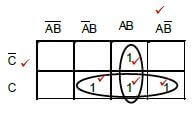
NOTE: Please take note of the mark allocation indicated for grouping.
- Q = AB +C(9)
6.5
6.5.1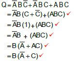 (5)
(5)
6.6
6.6.1
- A counter is used to count the number of pulses✔ before an activity can happen.✔
- The pulses could be anything that needs counting (2)
6.6.2
- Markers are used as a temporary storage space to hold a condition✔
- that must be carried from one sequence to another✔
- A marker is used to transfer the outcome of one rung to other rungs. (2)
6.6.3 A latch provides some kind of memory element.✔ It acts as a holding in contact. ✔ (2)
6.7
6.7.1 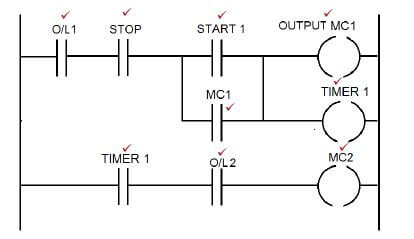 (9)
(9)
6.7.2 Motor starter with a time delay✔ (1) [40]
QUESTION 7: AMPLIFIERS
7.1
7.1.1 Negative✔ (1)
7.1.2 Positive✔ (1)
7.2 The gain ✔ of the circuit with no feedback ✔ (2)
7.3  (4)
(4)
7.4
- Audio application where the signal must be inverted✔
- Filters
- Oscillators
- Controllers (2)
7.5
7.5.1  (4)
(4)
Note:
Labelling = 2 marks
Waveform = 2 marks
7.5.2 Pulse generator✔ (1)
7.6  (4)
(4)
Note:
Labelling = 2 marks
Waveform = 2 marks
7.7  (4)
(4)
Note:
Labelling = 2 marks
Waveform = 2 marks
7.8
- High pass filters✔
- Square wave generators✔
- PID controllers (2)
7.9
- fr = 1
2π√LTC
= 1
2 × π × √2,2 × (47 × 10-9)
= 494,95Hz ✔ (3)
7.10 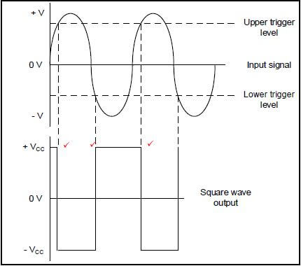 (3)
(3)
7.11
- Square wave generator✔
- Relaxation oscillators✔
- Clean noisy signal
- Interfacing analogue signal to digital circuitry (2)
7.12
7.12.1  (3)
(3)
7.12.2 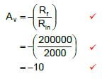 (3)
(3)
7.13
7.13.1
- Relaxation oscillator✔
- Memory elements✔ (2)
7.13.2 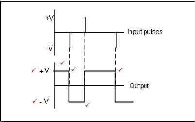 (6)
(6)
7.14
- fr = 1
2π√6RC
= 1
2 × π × √6 × 25 × 103 × (47 × 10-9)
= 55,3Hz ✔ (3)
[50]
TOTAL: 200