ELECTRICAL TECHNOLOGY GRADE 12 QUESTIONS - NSC PAST PAPERS AND MEMOS FEBRUARY/MARCH 2018
Share via Whatsapp Join our WhatsApp Group Join our Telegram GroupELECTRICAL TECHNOLOGY
GRADE 12
NSC PAST PAPERS AND MEMOS
FEBRUARY/MARCH 2018
INSTRUCTIONS AND INFORMATION
- This question paper consists of SEVEN questions.
- Answer ALL the questions.
- Sketches and diagrams must be large, neat and fully labelled.
- Show ALL calculations and round off answers correctly to TWO decimal places.
- Number the answers correctly according to the numbering system used in this question paper.
- You may use a non-programmable calculator.
- Show the units for ALL answers of calculations.
- A formula sheet is provided at the end of this question paper.
- Write neatly and legibly.
QUESTIONS
QUESTION 1: OCCUPATIONAL HEALTH AND SAFETY
1.1 Give ONE unsafe condition that may lead to an accident in a workshop. (1)
1.2 Explain who is responsible for ensuring safe working conditions in a workshop. (2)
1.3 Explain the term human rights with reference to working conditions in the workplace. (2)
1.4 Explain why a person under the influence of drugs may not operate machinery in the workplace. (2)
1.5 Explain the importance of carrying out a risk analysis in a workshop. (3) [10]
QUESTION 2: THREE-PHASE AC GENERATION
2.1 FIGURE 2.1 below shows a three-phase circuit. 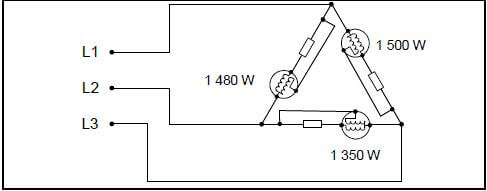
FIGURE 2.1: UNBALANCED THREE-PHASE CIRCUIT
2.1.1 Identify the method of power measurement. (1)
2.1.2 Explain why EACH wattmeter has one coil connected in parallel with the load and one coil connected in series. (3)
2.2 State TWO advantages of a three-phase distribution system over a single-phase distribution system. (2)
2.3 Refer to domestic dwellings and explain what information the kilowatt-hour meter provides. (2)
2.4 Two wattmeters are connected to measure the input power to a three-phase system. The readings on the wattmeters are 2,5 kW and 500 W respectively. Calculate the total power delivered to the load.
Given:
P1 = 2,5 kW
P2 = 500 W (3)
2.5 The load connected to a three-phase supply consists of three similar coils connected in star. The current drawn by the load is 25 A. The input power is 11 kW at a power factor of 0,8 lagging.
Given:
IL = 25 A
Pin = 11 kW
p.f. = 0,8 lagging
Calculate the:
2.5.1 Supply voltage (3)
2.5.2 Phase current (2)
2.6 Describe how a three-phase alternating-voltage supply is generated. (4) [20]
QUESTION 3: THREE-PHASE TRANSFORMERS
3.1 Describe how power is transferred from the primary to the secondary winding of a transformer. (5)
3.2 Name THREE cooling methods used in a transformer. (3)
3.3 Describe the cause of copper losses in transformers. (2)
3.4 A three-phase delta-star transformer has 1 500 turns per phase on the primary winding and 50 turns per phase on the secondary winding. The supply voltage is 3,3 kV. 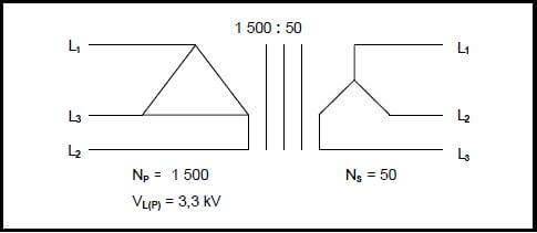
FIGURE 3.4: THREE-PHASE TRANSFORMER
Given:
NP = 1 500 turns
NS = 50 turns
VL(P) = 3,3 kV
Calculate the:
3.4.1 Turns ratio of the transformer (3)
3.4.2 Primary phase voltage (2)
3.4.3 Secondary phase voltage (3)
3.4.4 State, with a reason, whether the transformer in QUESTION 3.4 is a step-down or a step-up transformer. (2) [20]
QUESTION 4: THREE-PHASE MOTORS AND STARTERS
4.1 Refer to a three-phase squirrel-cage induction motor and answer the questions that follow.
4.1.1 State TWO advantages of this motor over a single-phase motor. (2)
4.1.2 State how the direction of rotation may be changed. (2)
4.1.3 Describe the basic operation of the motor. (7)
4.2 Explain why it is important to do a mechanical inspection of a motor before it is energised. (2)
4.3 Explain what will happen to the speed of an induction motor if the supply frequency is increased. (2)
4.4 Describe why an insulation test between windings must be carried out on an induction motor. (2)
4.5 Name ONE mechanical test that must be carried out on a motor before it is energised. (1)
4.6 A three-phase delta-connected motor draws a current of 9 A at full load and delivers an output power of 4 kW when connected to a 380 V/50 Hz supply. The motor has a power factor of 0,8.
Given:
VL = 380 V
IL = 9 A
POUT = 4 kW
f = 50 Hz
p.f. = 0,8
Calculate the following at full load:
4.6.1 Input power of the motor (3)
4.6.2 Efficiency of the motor (3)
4.7 FIGURE 4.7 below represents the control circuit of an automatic sequence starter. 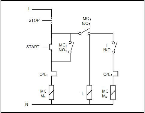
FIGURE 4.7: CONTROL CIRCUIT OF AN AUTOMATIC SEQUENCE STARTER
4.7.1 State the TWO conditions that must be met for the contact labelled MC1 N/O2 to close. (2)
4.7.2 Explain the function of the timer. (2)
4.7.3 State what determines the settings of O/L1 and O/L2. (1)
4.7.4 Describe the operation of the circuit. (5)
4.8 A star-delta starter is used to limit the starting current of a motor at start. Describe how the starter achieves its function. (3)
4.9 Explain how a contactor may be used as a switch. (3) [40]
QUESTION 5: RLC
5.1 FIGURE 5.1 below shows a capacitor connected to a 240 V/50 Hz supply.

FIGURE 5.1: CAPACITOR CIRCUIT
Given:
VT = 240 V
f = 50 Hz
XC = 27 Ω
5.1.1 Calculate the capacitance of the capacitor. (3)
5.1.2 Explain what will happen to the current flow if the supply frequency is increased. (3)
5.2 FIGURE 5.2 below shows a series RL circuit. Draw the phasor diagram that represents the circuit.

FIGURE 5.2: SERIES RL CIRCUIT (5)
5.3 FIGURE 5.3 below shows a parallel RL circuit connected to a 240 V/50 Hz supply. 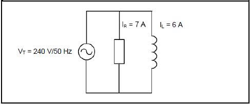
FIGURE 5.3: PARALLEL RL CIRCUIT
Given:
IR = 7 A
IL = 6 A
VT = 240 V
f = 50 Hz
Calculate the:
5.3.1 Inductive reactance (3)
5.3.2 Inductance (3)
5.3.3 Total current (3) [20]
QUESTION 6: LOGIC
6.1 Name FOUR main components of a simple PLC. (4)
6.2 State THREE advantages of a PLC system over a hardwired system. (3)
6.3 Draw a fully labelled block diagram of a PLC scan cycle. (3)
6.4 Write the simplified Boolean equation for the expression below. Use a three-variable Karnaugh map.
X =A B C+A B C+ ABC+ A B C(9)
6.5 Simplify the following Boolean equation by using Boolean algebra: (Show ALL the steps.)
Q = AB C+ AB C+ A B C(5)
6.6 Refer to a ladder logic diagram and explain the application of the following terms:
6.6.1 Counter (2)
6.6.2 Marker (2)
6.6.3 Latch (2)
6.7 Refer to FIGURE 6.7 below and answer the questions that follow. 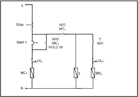
FIGURE 6.7
6.7.1 Draw the ladder logic diagram that will execute the same function in a PLC system. (9)
6.7.2 Give ONE example where the circuit in FIGURE 6.7 may be used in an electrical application. (1) [40]
QUESTION 7: AMPLIFIERS
7.1 State the polarity of the output voltage of the operational amplifier (op amp) in FIGURE 7.1 below for the following inputs, if:
7.1.1 V1 > V2 (1)
7.1.2 V1 < V2 (1) 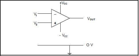
FIGURE 7.1: OP AMP
7.2 Explain the term open loop gain. (2)
7.3 FIGURE 7.3.1 below shows the input to a voltage comparator op amp in FIGURE 7.3.2. Draw the input signal and directly below that, on the same y-axis, draw the output signal. 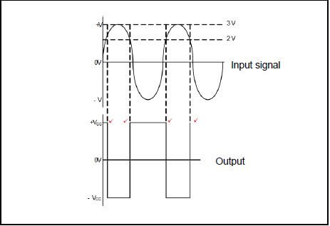
FIGURE 7.3.1: INPUT TO A VOLTAGE COMPARATOR OP AMP 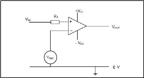
FIGURE 7.3.2: VOLTAGE COMPARATOR OP AMP (4)
7.4 Name TWO applications of an inverting amplifier. (2)
7.5 Refer to the astable multivibrator circuit diagram in FIGURE 7.5 below and answer the questions that follow. 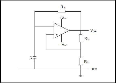
FIGURE 7.5: ASTABLE MULTIVIBRATOR
7.5.1 Draw a labelled output signal of the astable multivibrator. (4)
7.5.2 State ONE application of the astable multivibrator. (1)
7.6 FIGURE 7.6 below shows the input signal to an inverting comparator. The reference voltage is greater than zero. Draw the input signal and directly below that, on the same y-axis, draw the output signal. Label your answer. 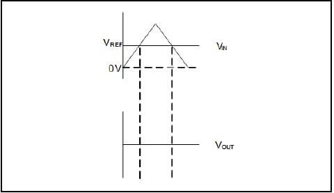
FIGURE 7.6: INPUT SIGNAL TO AN INVERTING COMPARATOR (4)
7.7 FIGURE 7.7 below shows the input signal to a non-inverting comparator. The reference voltage is equal to zero. Draw the input signal and directly below that, on the same y-axis, draw the output signal. Label your answer. 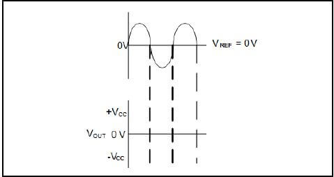
FIGURE 7.7: INPUT SIGNAL TO A NON-INVERTING COMPARATOR (4)
7.8 State TWO applications of the differentiator op amp. (2)
7.9 Calculate the resonant frequency of a Hartley oscillator op amp which has a 47 nF capacitor and two coils with a total inductance of 2,2 H connected in the circuit.
Given:
LT = 2,2 H
C = 47 nF (3)
7.10 FIGURE 7.10 below shows the input signal to a Schmitt trigger op amp. Draw the input signal and directly below that, on the same y-axis, draw the output signal when the Schmitt trigger is connected in the inverting configuration. 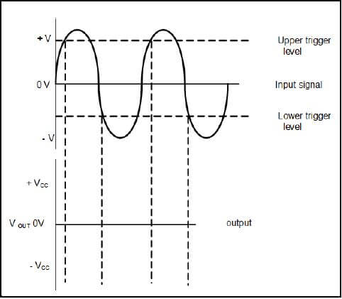
FIGURE 7.10: INPUT SIGNAL TO A SCHMITT TRIGGER OP AMP (3)
7.11 State TWO applications of a Schmitt trigger. (2)
7.12 An input voltage of 10 V is supplied to the input of an inverting amplifier circuit with an input resistor of 20 kΩ and a feedback resistor of 200 kΩ. The amplifier circuit is connected to a split voltage supply. Calculate the:
7.12.1 Output voltage of the amplifier (3)
7.12.2 Amplification factor of the amplifier (3)
7.13 Refer to FIGURE 7.13.1 below and answer the following questions. 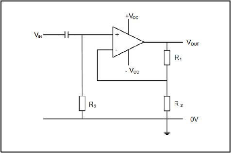
FIGURE 7.13.1: BISTABLE MULTIVIBRATOR OP AMP CIRCUIT
7.13.1 State TWO applications of the op amp. (2)
7.13.2 Draw the input trigger pulse in FIGURE 7.13.2 below and directly below that, on the same y-axis, the correct output in relation to the given input. Take the initial output voltage as maximum positive. 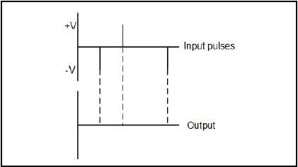
FIGURE 7.13.2 (6)
7.14 Calculate the resonant frequency of a three-stage RC phase-shift oscillator with resistors values of 25 kΩ and capacitors values of 47 nF. (3) [50]
TOTAL: 200