CIVIL TECHNOLOGY GRADE 12 QUESTIONS - NSC PAST PAPERS AND MEMOS FEBRUARY/MARCH 2018
Share via Whatsapp Join our WhatsApp Group Join our Telegram GroupCIVIL TECHNOLOGY
GRADE 12
NSC PAST PAPERS AND MEMOS
FEBRUARY/MARCH 2018
REQUIREMENTS:
- Drawing instruments
- A non-programmable pocket calculator
- ANSWER BOOK
INSTRUCTIONS AND INFORMATION
- This question paper consists of SIX questions.
- Answer ALL the questions.
- Answer each question as a whole. Do NOT separate subsections of questions.
- Start the answer to EACH question on a NEW page.
- Do NOT write in the margins of the ANSWER BOOK.
- You may use sketches to illustrate your answers.
- Write ALL calculations and answers in the ANSWER BOOK or on the attached ANSWER SHEETS.
- Use the mark allocation as a guide to the length of your answers.
- Make drawings and sketches in pencil, fully dimensioned and neatly finished off with descriptive titles and notes to conform to the SANS/SABS Code of Practice for Building Drawings.
- For the purpose of this question paper, the size of a brick should be taken as 220 mm x 110 mm x 75 mm.
- Use your own discretion where dimensions and/or details have been omitted.
- Answer QUESTIONS 1.12, 3.6, 3.7, 4.6, 5.2, 5.3, 6.1 and 6.2 on the attached ANSWER SHEETS using drawing instruments, where necessary.
- Write your CENTRE NUMBER and EXAMINATION NUMBER on every ANSWER SHEET and hand them in with your ANSWER BOOK, whether you have used them or not.
- Due to electronic transfer, drawings in the question paper are NOT to scale.
- Google Images was used as the source for all photographs and pictures.
QUESTIONS
QUESTION 1: CONSTRUCTION, SAFETY AND MATERIAL
1.1 Choose a description from COLUMN B that matches an item in COLUMN A. Write only the letter (A–L) next to the question number (1.1.1–1.1.10) in the ANSWER BOOK, for example 1.1.11 M.
COLUMN A | COLUMN B |
1.1.1 Lintel |
|
(10 x 1) (10)
1.2 FIGURE 1.2 below shows two different safety signs for personal protection.
 |  |
| A | B |
FIGURE 1.2
1.2.1 Explain when you would use safety boots A. (1)
1.2.2 Explain when you would use gum boots B. (1)
1.3 Give ONE reason why the rungs of a ladder should not be painted. (1)
1.4 Describe TWO safety precautions that must adhered to to ensure the safety of workers and the public during deep excavations. (2)
1.5 Name THREE accessories that you need to conduct a cube test. (3)
1.6 Name the purpose of water during the mixing process of concrete. (1)
1.7 Give ONE reason why you would use a damp-proof course in the following places:
1.7.1 In the walls of a basement (1)
1.7.2 Between a floor and a wall (1)
1.8 Name the preservative that you would use on timber if you want to see its natural colour. (1)
1.9 Name the type of roof covering that you would use if the roof covering is fixed on top of 38 mm x 38 mm battens. (1)
1.10 Name the roof component that you would use to close the gap where the roof coverings meet at the top of a roof. (1)
1.11 What will you use to join the roof truss members if the members have butt joints? (1)
1.12 FIGURE 1.12 on ANSWER SHEET 1.12 shows an incomplete drawing in stretcher bond of a plan course of a one-brick wall with a half-brick T-junction.
Complete the drawing by placing ALL the missing bricks, including the three quarter bricks, in the correct spaces. The bricks you draw must be of the same size as those on the given drawing. (5) [30]
QUESTION 2: ADVANCED CONSTRUCTION AND EQUIPMENT
Start this question on a NEW page.
2.1 Various options are given as possible answers to the following questions. Choose the answer and write only the letter (A–D) next to the question number (2.1.1–2.1.5) in the ANSWER BOOK,
for example 2.1.6 C.
2.1.1 The … is used to measure and set horizontal distances, vertical heights and angles.
- mortice
- mitre square
- dumpy level
- builder's square (1)
2.1.2 A transparent pipe can be used for …
- setting out foundations.
- marking perpendicular lines.
- testing the squareness of objects.
- transferring heights from one point to another. (1)
2.1.3 This hammer is mainly used to drive very small nails into wood:
- Cross-peen hammer
- Claw hammer
- Rubber mallet
- Wooden mallet (1)
2.1.4 A/An … is used to cut steel.
- portable circular saw
- angle grinder
- electric mitre saw
- sliding bevel (1)
2.1.5 A … is used for cutting along the length of wood.
- ripsaw
- crosscut saw
- portable electric planer
- panel saw (1)
2.2 FIGURE 2.2 below shows power tools and equipment that are used in the building industry. Write down the name and explain ONE use of each power tool next to the question number (2.2.1–2.2.2) in the ANSWER BOOK.
| 2.2.1 | 2.2.2 |
 |  |
FIGURE 2.2 (4)
2.3 Name the hand tool that you will use to spring a straight line between two points. (1)
2.4 Name ONE hand tool that you would use during the building process to ensure that the corner of the walls of a house is square. (1)
2.5 Differentiate between a rough arch and a gauged arch in terms of the type of brick used to build the arch. (2)
2.6 FIGURE 2.6 below is a drawing of a pile. Study the drawing and answer the questions that follow. 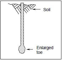
FIGURE 2.6
2.6.1 Name the type of pile in FIGURE 2.6. (1)
2.6.2 Describe TWO factors that will determine the use of this type of pile. (2)
2.6.3 Name the material that can be placed inside the pile to make the concrete in the pile stronger. (1)
2.7 FIGURE 2.7 below shows two types of reinforcing bars that can be used for reinforcing concrete. Study the figure and name EACH reinforcing bar. Write down the answer next to the number (2.7.1–2.7.2) in the ANSWER BOOK. 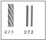
FIGURE 2.7 (2)
2.8 FIGURE 2.8 below illustrates a flight of concrete stairs. Study the drawing and name parts A to C in the ANSWER BOOK. 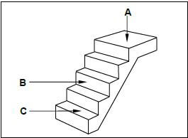
FIGURE 2.8 (3)
2.9 Name TWO defects that can occur in concrete due to shuttering. (2)
2.10 FIGURE 2.10 below shows a sectional view of an external wall. 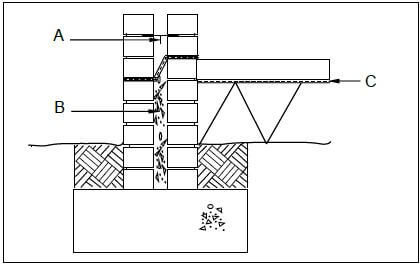
FIGURE 2.10
2.10.1 Identify the type of wall. (1)
2.10.2 Identify part A and explain the function of this part. (2)
2.10.3 Name the type of mixture that is used for B. (1)
2.10.4 Explain ONE reason for filling part B with this type of mixture. (1)
2.10.5 Identify part C. (1)
2.10.6 Give the minimum distance of the opening in the wall in FIGURE 2.10. (1)
2.11 FIGURE 2.11 below illustrates an incomplete vertical sectional view through a dry wall. Study the sketch and answer the questions that follow. 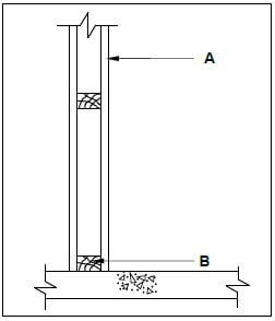
FIGURE 2.11
2.11.1 Identify parts A and B. (2)
2.11.2 Name any other material that B can be made of. (1)
2.11.3 Explain TWO advantages of dry walls. (2)
2.12 FIGURE 2.12 below is a sketch of components of a suspended floor. 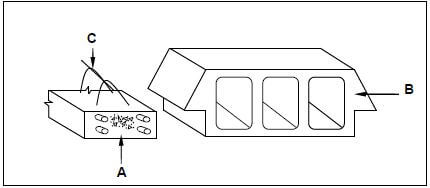
FIGURE 2.12
2.12.1 Name the type of suspended floor where these components will be used. (1)
2.12.2 Identify parts A to C. (3) [40]
QUESTION 3: CIVIL SERVICES
Start this question on a NEW page.
3.1 FIGURE 3.1 below shows a water trap that is used in civil services. 
FIGURE 3.1
3.1.1 Identify the water trap. (1)
3.1.2 Name ONE place where the trap can be used. (1)
3.2 FIGURE 3.2 below shows an electrical water-heating system. Study the sketch and answer the questions that follow. 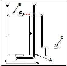
FIGURE 3.2
3.2.1 Explain the functions of pipes A and B as used in the geyser installation. (2)
3.2.2 Explain the purpose of C. (1)
3.2.3 Give ONE reason for using a drip tray in a geyser installation. (1)
3.3 FIGURE 3.3 below is a drawing of an open storm-water channel. Study the drawing and answer the questions that follow. 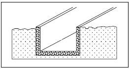
FIGURE 3.3
3.3.1 Explain the term storm water. (1)
3.3.2 Explain the function of storm-water channels. (1)
3.4 Describe ONE advantage of shallow water wells. (1)
3.5 Water from a borehole is extracted by using an electric pump, a hand operated pump or a solar-powered pump. Name ONE other method that can be used to extract water from a borehole. (1)
3.6 FIGURE 3.6 on ANSWER SHEET 3.6 shows an incomplete floor plan of a kitchen. Complete the drawing by drawing the symbols and wiring for the following electrical fittings:
3.6.1 Two-way switch at A (2)
3.6.2 Socket outlet at B (2)
3.6.3 Light at C (2)
3.6.4 Electrical wiring from A to C (2)
3.7 FIGURE 3.7 on ANSWER SHEET 3.7 shows the incomplete layout of a one-pipe sewerage system connected to a conservancy tank. Study the drawing and draw the layout of the sewerage system on ANSWER SHEET 3.7. All regulations and design principles of a good sewerage system must be adhered to.
The sewerage system must consist of the following and it should be indicated with the correct drawing symbols:
- 1 x rodding eye (1)
- 1 x gully at the kitchen sink (1)
- 1 x ventilation pipe (1)
- Main sewerage pipes (2)
- 4 x inspection eyes (4)
- 1 x manhole (1)
- Any TWO abbreviations for the sanitary fixtures (2) [30]
QUESTION 4: QUANTITIES, MATERIALS AND JOINING
Start this question on a NEW page.
4.1 Below are pictures of fasteners that are used on building sites and in workshops. Write down the name and ONE use of EACH fastener next to the question number (4.1.1–4.1.3) in the ANSWER BOOK.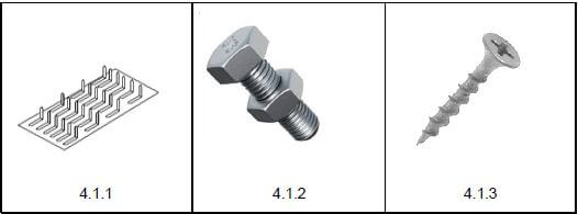 (6)
(6)
4.2 Name ONE fastener that you will use to fix a truss hanger to a wall. (1)
4.3 Name ONE method of joining copper pipes. (1)
4.4 Name TWO advantages of screws when compared to nails. (2)
4.5 FIGURE 4.5 on the next page shows the brandering layout of a ceiling construction and the four walls. Study the drawing and complete the incomplete cutting list. Write down the answer next to the question number (4.5.1 to 4.5.7) in the ANSWER BOOK.
Use the following specifications to answer the question.
- Ceiling board: 6,4 mm x 900 mm x 3 000 mm
- Brandering: 38 mm x 38 mm
- Brandering is placed 75 mm away from each wall.
- Cornice: 75 mm x 75 mm
- Metal cover strips: 7 mm x 20 mm x 3 000 mm
- The longest brander (brandering) touches the short walls.
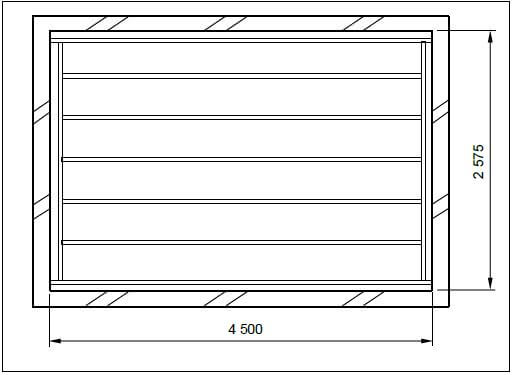 FIGURE 4.5
CUTTING LIST FOR CEILING | |||||||
MEMBER | QUANTITY | UNIT | LENGTH | WIDTH THICKNESS | TOTAL LENGTH | MATERIAL | |
Long-wall branders (brandering) | 2 | mm | 4 575 | 4.5.1 | 38 | 9 150 | SA pine |
Short-wall branders (brandering) | 2 | mm | 4.5.2 | 38 | 38 | 10 300 | SA pine |
Intermediate branders (brandering) | 4.5.3 | mm | 4 349 | 38 | 38 | 21 745 | SA pine |
Ceiling boards | 5 | mm | 4.5.4 | 900 | 6,4 | 11 780 | Gypsum board |
Cornices: Short wall | 2 | mm | 2 575 | 75 | 75 | 4.5.5 | Gypsum board |
Cornices: Long wall | 2 | mm | 4.5.6 | 75 | 75 | 9 150 | Gypsum board |
Metal cover strips | 4 | mm | 2 575 | 20 | 7 | 4.5.7 | Steel/ Aluminium |
(7)
4.6 FIGURE 4.6 below shows the floor plan of a room. You must install ceiling boards and skirtings in this room.
SPECIFICATIONS:
- External measurements of the room: 6 500 mm x 3 800 mm
- The external walls are one-brick walls (220 mm).
- Door opening: 2 100 mm x 900 mm
- Size of ceiling boards: 3 900 mm x 900 mm
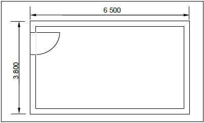 FIGURE 4.6
Use ANSWER SHEET 4.6 and answer the following questions.
4.6.1 Calculate the inside floor area of the room in square metres (m²). Round off your answer to TWO decimals. (6)
4.6.2 Calculate the area of ONE ceiling board in square metres (m²). (3)
4.6.3 Calculate the total length of the skirtings for the room in metres (m). (4) [30]
QUESTION 5: APPLIED MECHANICS
Start this question on a NEW page.
5.1 FIGURE 5.1 below shows a shaped lamina. All dimensions are in millimetres.
Study the lamina and calculate the centroid of the lamina from B–B. Round off your answer to TWO decimal places.
HINT: Use the formula on the FORMULA SHEET 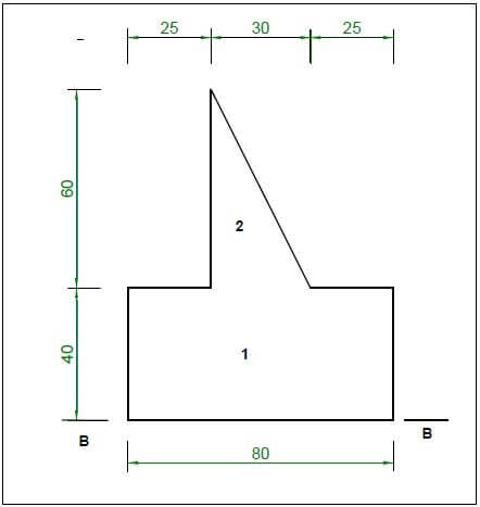
FIGURE 5.1 (10)
5.2 FIGURE 5.2 below shows the space diagram of a truss with two point loads and a span of 10 metres. 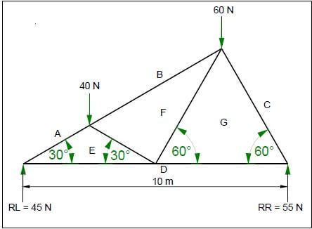
FIGURE 5.2
5.2.1 Use ANSWER SHEET 5.2 and develop and draw a vector diagram to determine the nature and magnitude of the forces in the members of the truss graphically.
Use scale 1 mm = 1 N. (8)
5.2.2 Use the information in the space diagram and vector diagram and complete the table on ANSWER SHEET 5.2. (4)
5.3 FIGURE 5.3 below shows the space diagram of a beam with a span of 10 metres, with three point loads and a uniformly distributed load. Study the diagram and answer the questions that follow.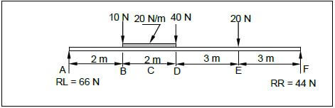
FIGURE 5.3
5.3.1 Convert the uniformly distributed load to a point load and write down the value of the converted point load. (1)
5.3.2 Determine the distance of the converted uniformly distributed load that now is a point load from RR. (1)
5.3.3 Determine the distance of the converted uniformly distributed load that now is a point load from RL. (1)
5.3.4 The value of the bending moments at A = 0 Nm, B = 132 Nm, C = 178 Nm, D = 204 Nm, E = 132 Nm and F = 0 Nm. Use ALL the available information and draw the bending moment diagram on ANSWER SHEET 5.3. Use scale 1 mm = 2 Nm. (5) [30]
QUESTION 6: GRAPHICS AND COMMUNICATION
6.1 FIGURE 6.1 below shows the west elevation of a proposed dwelling. Study the drawing and complete the table on ANSWER SHEET 6.1. 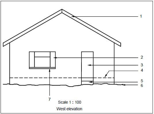
FIGURE 6.1 (15)
6.2 FIGURE 6.2 below shows the floor plan of a site office with a gable roof with open eaves. 
FIGURE 6.2
Draw on ANSWER SHEET 6.2, to scale 1 : 20, a sectional view on section line A–A. Show the top 600 mm of the wall and just more than half of the king post roof truss. Start your drawing from corner A on ANSWER SHEET 6.2.
Use the specifications on the next page.
SPECIFICATIONS:
- Wall: 220 mm wide, plastered on both sides
- Plaster: 20 mm thick
- Wall plate: 114 mm x 38 mm
- Span of roof: 4 110 mm
- A king post roof truss with an open eave is used.
- Slope of roof: 30°
- Tie beam: 114 mm x 38 mm
- Rafters: 114 mm x 38 mm
- King post: 114 mm x 38 mm
- Branders (Brandering): 38 mm x 38 mm on 450 mm centre to centre
- Gypsum ceiling board: 6 mm
- Cornice: 75 mm x 75 mm
- Eaves overhang: 500 mm
Print the title and scale below the drawing.
Print any FOUR labels on the drawing. (25) [40]
TOTAL: 200
CENTRE NUMBER: |
EXAMINATION NUMBER: |
ANSWER SHEET 1.12 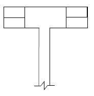
FIGURE 1.12
ASSESSMENT CRITERIA | MARK | CANDIDATE'S MARK |
One-brick wall | 2 | |
Half-brick wall (T-junction) | 1 | |
Three-quarter bricks | 2 | |
TOTAL | 5 |
CENTRE NUMBER: |
EXAMINATION NUMBER: |
ANSWER SHEET 3.6 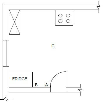
FIGURE 3.6
ASSESSMENT CRITERIA | MARK | CANDIDATE'S MARK |
2-way light switch | 2 | |
Socket outlet | 2 | |
Light | 2 | |
Electrical wiring | 2 | |
TOTAL | 8 |
CENTRE NUMBER: |
EXAMINATION NUMBER: |
ANSWER SHEET 3.7 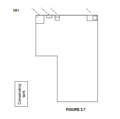
FIGURE 3.7
ASSESSMENT CRITERIA | MARK | CANDIDATE'S MARK |
Rodding eye | 1 | |
Gully | 1 | |
Ventilation pipe | 1 | |
Main sewerage pipes | 2 | |
Inspection eyes | 4 | |
Manhole | 1 | |
Any TWO abbreviations for the sanitary fixtures | 2 | |
TOTAL | 12 |
SDFS
CENTRE NUMBER: |
EXAMINATION NUMBER: |
ANSWER SHEET 4.6
Complete your answers in the spaces indicated with _____________.
A | C | D | |
Inside measurement of room: | |||
Long walls = mm – _____ mm | |||
= mm | |||
Short walls = mm – _____ mm | |||
= _____ mm | |||
(4) | |||
1/ | ______ | Inside floor area of room: | |
______ | _____ m² | (2) | |
Area of one ceiling board: | |||
1/ | One board is 3 900 mm x 900 mm. | ||
_______ | _____ m² | (3) | |
Length of skirtings: | |||
= | |||
= | |||
= | |||
(4) | |||
(13) |
CENTRE NUMBER: |
EXAMINATION NUMBER: |
ANSWER SHEET 5.2
5.2.1 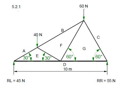
 (8)
(8)
5.2.2
MEMBER | NATURE | MAGNITUDE |
FG | ||
BF |
Tolerance of 1 N to either side (4)
CENTRE NUMBER: |
EXAMINATION NUMBER: |
ANSWER SHEET 5.3 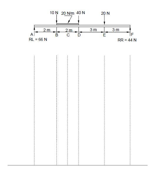
CENTRE NUMBER: |
EXAMINATION NUMBER: |
ANSWER SHEET 6.1
NO. | QUESTIONS | ANSWERS | MARKS |
1 | Name the scale used for the west elevation. | 1 | |
2 | Identify number 1. | 1 | |
3 | Identify number 2. | 1 | |
4 | Identify number 3. | 1 | |
5 | Identify number 4. | 1 | |
6 | Identify number 5. | 1 | |
7 | Identify number 6. | 1 | |
8 | Identify number 7. | 1 | |
9 | Name the material that can be used for the soffit board at a closed eave. | 1 | |
10 | Recommend a suitable exterior finish for the wall. | 1 | |
11 | On which elevations will the gutters of this house be placed? | 2 | |
12 | Draw the roof lines for the roof of the building shown in FIGURE 6.1 in the column alongside. |  | 3 |
TOTAL | 15 |
CENTRE NUMBER: |
EXAMINATION NUMBER: |
ASSESSMENT CRITERIA | MARKS | LM |
Correctness of drawing | 3 | |
External wall | 1 | |
Symbol for wall | 1 | |
Plaster | 2 | |
Wall plate | 1 | |
Tie beam | 1 | |
Rafters | 2 | |
King post | 1 | |
Branders (Brandering) | 1 | |
Ceiling board | 1 | |
Cornice | 1 | |
Fascia board | 1 | |
Print title and scale | 2 | |
Any FOUR labels | 4 | |
Application of scale:
| 3 | |
TOTAL | 25 |
ANSWER SHEET 6.2 
FORMULA SHEET
IMPORTANT ABBREVIATIONS
| SYMBOL | DESCRIPTION | SYMBOL | DESCRIPTION | SYMBOL | DESCRIPTION |
| c | Centroid | b | Breadth/Width | r | Radius |
| ℓ | Length | s | Side | A | Area |
FORMULAE
| AREA OF | FORMULA (in words) | FORMULA (in symbols) | FORMULA FOR THE POSITION OF CENTROIDS | |
| X-axis | Y-axis | |||
| Square | side x side | s x s | s 2 | s 2 |
| Rectangle | length x breadth | ℓ x b | ℓ 2 | b 2 |
| Right-angled triangle | ½ x base x height | ½b x h | b 3 | h 3 |
| Equilateral triangle/ Isosceles triangle | ½ x base x height | ½b x h | b 2 | h 3 |
Position of centroid = (A1 x d) ± (A2 x d)
Total area
OR
Y = ΣAy
ΣA
OR
X = ΣAx
ΣA