MECHANICAL TECHNOLOGY GRADE 12 MEMORANDUM - NSC PAST PAPERS AND MEMOS NOVEMBER 2017
Share via Whatsapp Join our WhatsApp Group Join our Telegram GroupMECHANICAL TECHNOLOGY
GRADE 12
MEMORANDUM
NOVEMBER 2017
NATIONAL SENIOR CERTIFICATE
QUESTION 1: MULTIPLE-CHOICE QUESTIONS
1.1 B ✓ (1)
1.2 C ✓ (1)
1.3 D ✓ (1)
1.4 B ✓ (1)
1.5 C ✓ (1)
1.6 D ✓ (1)
1.7 D ✓ (1)
1.8 C ✓ (1)
1.9 B ✓ (1)
1.10 B ✓ (1)
1.11 A ✓ (1)
1.12 C ✓ (1)
1.13 B ✓ (1)
1.14 B ✓ (1)
1.15 B ✓ (1)
1.16 D ✓ (1)
1.17 B✓ (1)
1.18 B ✓ (1)
1.19 B ✓ (1)
1.20 A ✓ (1)
[20]
QUESTION 2: SAFETY
2.1 Surface grinder:
- Make sure the sparks are of no danger to co-workers. ✓
- Do not force the material onto the grinding wheel. ✓
- Do not plunge grind. ✓
- Bring the material slowly into contact with the grinding wheel. ✓
- Never clean or adjust the machine while it is in motion. ✓
- Use cutting fluid ✓
- Know where the emergency stop is located ✓
- Stop the machine before any adjustments ✓
- Keep tools clear from moving parts ✓
(Any 3x1) (3)
2.2 Hydraulic press:
- To make sure there is no leakages. ✓
- To make sure that the readings are accurate. ✓
- To make sure the prescribed pressure is not exceeded. ✓(2)
2.3 MIG/MAGS welding:
- Working area must be well ventilated. ✓
- Make sure electrical parts are properly insulated. ✓
- Make sure the inert gas cylinder is fixed in an upright position. ✓
- Make sure the terminals are connected correctly to the right outlet points. ✓
- The operator should know how to use the equipment.✓
- The operator must be completely insulated by means of boots, gloves and rubber mats. ✓
- The work area must be partitioned off. ✓
- Use protective equipment. (Overall, gloves, apron, welding helmet etc.) ✓
- Ensure adequate fire precautions. ✓
- See that there is no oil or grease around the machine. ✓
- Ensure that the working area is clean. ✓
(Any 3x1) (3)
2.4 Spring compressor:
- Make certain the compressor is strong enough for the spring ✓
- The compressor must be fitted correctly and firmly. ✓
- Ensure that the spring cannot slip out of position. ✓
- A uniform load must be applied. ✓
- Release the load carefully and also uniformly. ✓
- Do not use wire or ropes to compress the spring. ✓
- Do not hit with a hammer. ✓
- The hookes on the clamps shoul not be warned ✓
- Clamps must be evenly distributed ✓
- Do not exceed the maximum tension ✓
(Any 2x1) (2)
[10]
QUESTION 3: TOOLS AND EQUIPMENT
3.1 Volt and ammeter:
- Voltmeter: connected in parallel to a circuit. ✓
- Ammeter: connected in series to a circuit. ✓ (2)
3.2 Uses of the multimeter:
- Direct current measurement (DC) ✓
- Alternating current measurement (AC) ✓
- Voltage measurement ✓
- Resistance measurement ✓
- Transistor test ✓
- Diode test ✓
- Continuity test ✓
- Temperature ✓
- Battery test ✓
(Any 4x1) (4)
3.3 Compression Test:
- The piston rings are worn out. ✓✓
- Worn cylinders. ✓✓
- Cracked piston. ✓✓
(Any 1x2) (2)
3.4 Tests:
3.4.1 A beam bending test is to investigate the deflection / bend ✓✓ of beams. (2)
3.4.2 A cylinder leakage tester is to check whether gases or air leaks ✓✓ from the cylinders / valve leak. (2)
[12]
QUESTION 4: MATERIALS
4.1 Properties of structures:
4.1.1 Cementite: hard ✓ and brittle ✓ (2)
4.1.2 Ferrite: soft ✓ and ductile ✓ (2)
4.2 Heating process of carbon steel:
4.2.1 Iron-Carbon ✓ Equilibrium ✓ Diagram (2)
4.2.2
- = Ferrite and pearlite ✓
- = Pearlite and cementite ✓
- = Ferrite and austenite ✓
- = Austenite and cementite ✓
- = Austenite ✓ (5)
4.2.3 700 – 800 °C ✓✓ (2)
[13]
QUESTION 5: TERMINOLOGY
5.1 Screw thread terms: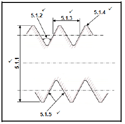
5.1.3: NOTE: Any other corresponding point on the screw thread (5)
5.2 Milling processes:
5.2.1 Up-cut milling ✓ (1)
5.2.2 Down-cut milling ✓ (1)
5.3 Indexing:
Indexing = 40
A
= 40
22
= 1 18 x 3
22 3
= 1 54
66
1 full turn and 54 holes on the 66-hole circle (6)✓✓✓✓✓✓
5.4 Dividing head:
5.4.1 The sector arm save time and removes the possibility of error in counting the number of holes for each move of the index pin. ✓ (2)
5.4.2 The index plate is equipped with accurate spaced holes on different-diameter circles. Each circle has a different number of holes. These circles allow the crank handle to be given an accurate part of a turn to obtain the desired spacing. ✓✓ (2)
5.4.3 The index pin can be set in the crank handle so that it can be dropped into calculated hole and lock the crank the hole circles. ✓✓ (2)
5.4.4 Ratio between worm and worm gear: 40:1 ✓✓ (2)
5.5 Gear terminology:
5.5.1 The pitch-circle diameter 'PCD'
module(m) = PCD
T
PCD = m x T
= 3 x 94
PCD = 282mm (3)✓✓✓
5.5.2 The outside diameter:
outside diameter = PCD + 2m
OD = 282+2(3)
OD = 288mm (2)✓✓
5.5.3 The dedendum:
Dedendum b = 1.157m
b = 1.157 x 3
b = 3.47mm
or
b = 1.25m
b = 1.25 x 3
b = 3.75mm (2)✓✓
5.5.4 The cutting depth:
Cutting dept = 2.157 x m
= 2.157 x 3
= 6.47 mm
or
Cutting depth = 2.25 x m
= 2.25 x 3
= 6.75mm (2)✓✓
[30]
QUESTION 6: JOINING METHODS
6.1 Causes of undercutting:
- Current setting is too high ✓
- Current setting is too low ✓
- Faulty electrode manipulation ✓
- Arc length is too long ✓
- Welding speed is too fast ✓
- Incorrect electrode size ✓
(Any 2x1) (2)
6.2 Prevention of slag inclusion:
- Chip off the slag from the previous weld runs before doing any further welding. ✓✓
- Increase the current setting. ✓✓
- Ensure that the joint is properly cleaned before any welding is done. ✓✓
- Ensure constant current flow. ✓✓
- Arc length must be shorter ✓✓
- Use dry electrodes
(Any 1x2) (2)
6.3 Liquid dye penetrant test:
- Dye is sprayed onto the clean surface to be inspected ✓
- Allow a short time for the dye to penetrate, then remove excess dye with a solvent ✓
- Wash surface with water and allow to dry✓
- When the surface is dry spray a developer on the surface to bring out the colour in the dye which is trapped in the cracks or pin holes ✓ (4)
6.4 Advantages of using a MIGS/MAGS welding:
- Operator needs less skills ✓
- Continuous welds can be done without replacing electrodes✓
- Less cleaning of weld, (No slag to be removed) ✓
- It is a quicker process ✓
- Thin material can be welded easily ✓
- Can weld in any position ✓
- Create a better finish ✓
- High deposition rate ✓
- Less distortion ✓
(Any 3x1) (3)
6.5 Gas flow meter:
Control the flow of rate of shielding gas ✓ and measure the flow rate. ✓ (2)
6.6 MIGS/MAGS welding process:
- = Melted welding pool / Parent metal / Weld metal / Weld ✓
- = Contact nozzle / Weld pistol / gun✓
- = Gas shroud / Weld pistol / gun ✓
- = Shielding gas ✓
- = Earth clamp / Skelm / Earth cable ✓ (5)
6.7 Shielding gas in MIGS/MAGS:
- To control the welding arc ✓✓
- Shield the molten pool from atmospheric gases ✓✓
(Any 1x2) (2)
6.8 Earth cable:
- To complete the circuit ✓✓
- To maintain constant current ✓✓
- To prevent electric shock ✓✓
(Any 1x2) (2)
6.9 THREE types of gasses used for MIGS/MAGS welding:
- Argon ✓
- Teral ✓
- CO2 ✓
- Helium ✓
- Gas mixture ✓
(Any 3x1) (3)
[25]
QUESTION 7: FORCES
7.1 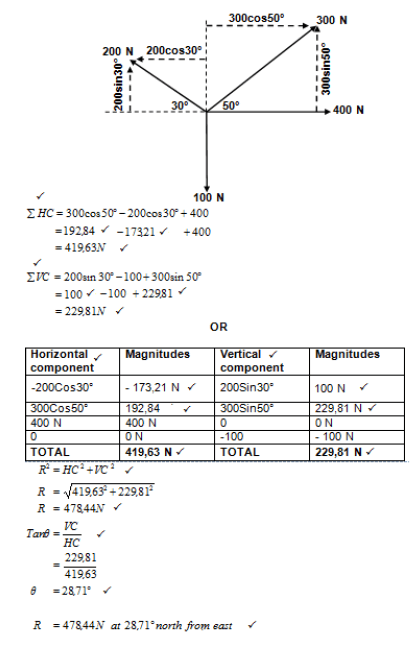 (13)
(13)
7.2 Stress and Strain:
7.2.1 Stress in the bar:
A = πD2
4
= π x 0.0562
4
= 2.46 x 10⁻³m-2
σ = F
A
= 40 x 10 3
2.46 x 10-3
= 16260162.6Pa
= 16.26 x 10⁶Pa
= 16.26MPa (5)✓✓✓✓✓
7.2.2 Strain:
ε = σ
E
ε = 16.26 x 10⁶
90 x 109
= 0.18 x 10⁻³(3)✓✓✓
7.2.3 Change in length:
ε = Δl
ol
Δl = ε x ol
= (0.18 x 10-3) x 0.85
= 0.15 x 10⁻³m
OR
= 0.15 mm(3)✓✓✓
7.3 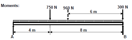
Calculate A. Moments about B:
∑RHM = ∑LHM
(A x 12) = (960 x 6) + (750 x 8)
12A = 5760 + 6000
12 12
A = 980N
Calculate B. Moments about A:
∑RHM = ∑LHM
(B x 12) = (750 x 4) + (960 x 6) + (300 x 12)
12B = 3000 + 5760 + 3600
12B = 12360
12 12
B = 1030N (6)✓✓✓✓✓✓
[30]
QUESTION 8: MAINTENANCE
8.1 Pour point:
The lowest temperature ✓ at which a liquid will flow. ✓ (2)
8.2 Advantages of cutting fluids:
- Keep the work piece and cutting tool cool ✓
- It prolongs the life of the cutting tool ✓
- Ensure a better finish ✓
- It washes the cuttings/swarf away ✓
- It protects the machine by making the cutting process easier ✓
- Prevents rust ✓
- It increases the productivity because ✓
- It is possible to cut faster ✓
- It lubricates the machine ✓
(Any 3x1) (3)
8.3 'ATF':
Automatic transmission fluid ✓✓ (2)
8.4 Main parts of a clutch:
Pressure plate ✓ clutch plate ✓ release bearing (Thrust bearing) ✓ (3)
8.5 Results of a stretched chain:
- The chain weakens ✓
- Generates friction ✓
- Vibration occurs ✓
- Becomes noisy ✓
- Derails easily ✓
- Tends to break easily ✓
(Any 3x1) (3)
8.6 Causes of belt slip:
- Incorrect tension (loose) ✓
- Oil on the contact surfaces ✓
- Worn belts ✓
- Incorrect pulley alignment ✓
- Overloading ✓
- Not the correct size ✓
(Any 2x1) (2)
[15]
QUESTION 9: SYSTEM AND CONTROLS
9.1 Gear drives:
9.1.1 Rotation frequency of the output shaft:
NF = TA x TC x TE
NA TBx TD x TF
NF = TA x TC x TE x NA
TB x TD x TF
NF = 30 x 20 x 50 x 2300
40 x 60 x 70
=410.71r/min (3)✓✓✓
9.1.2 Velocity Ratio:
VR = NINPUT
NOUTPUT
= 2300
410.71
= 5.6:1 (2)✓✓
or
VR = NOUTPUT
NINPUT
= 410.71
2300
= 1:0.178
9.2 Belt Drives:
9.2.1 Rotation frequency of the driven pulley:
V = πDn
n = V
πD
= 32
πx(0.26)
nr/min = 39.18 x 60
nr/min = 2350.6r/min (3)✓✓✓
9.2.2 Tensile force in the tight side:
T1 = 2.5
T2
T1 = 2.5 x T2
=2.5 x 140
=350N (2)
9.2.3 Power transmitted:
P = (T1 - T2)v
P = (350 - 140)x 32
=6720 watts (3)✓✓✓
9.3 Hydraulics:
9.3.1 Fluid pressure:
AA = πD2
4
= π0.022
4
= 0.31 x 10⁻³m2
PA = F
AA
= 300 Pa
0.31 x 10-3
= 967741.94Pa
= 0.97 x 10⁶Pa
= 0.967 MPa (4)✓✓✓✓
9.3.2 Stroke at piston B:
AB = πD2
4
= π0.0752
4
= 4.42 x 10⁻³m2
VB = VA
\AB x LB = AB x LA
LB = AA x LA
AB
= (0.31 x 10-3) x 185
4.42 x 10-3
= 12.98mm (4)✓✓✓✓
9.4 Traction control:
It prevents the wheels from spinning ✓✓(2)
9.5 Safety belt:
Safety belts need to be activated (buckle up) by the driver/passenger ✓✓ (2)
[25]
QUESTION 10: TURBINES
10.1 Water turbine:
- Waterwheel ✓
- Pelton ✓
- Turgo ✓
- Michell-Banki ✓
- Jonval turbine ✓
- Reverse overshot waterwheel ✓
- Archimedes’ screw turbine ✓
(Any 1x1) (1)
10.2 Runaway speed of a water turbine:
Runaway speed of a water turbine is its speed at full flow ✓ and with no shaft load ✓ (2)
10.3 Water turbine:
10.3.1 Type of turbine:
- Reaction turbine ✓
- Kaplan turbine ✓
(Any 1x1) (1)
10.3.2
- Wicket gate ✓
- Rotor ✓
- Stator✓
- Shaft ✓
- Water flow ✓
- Blades✓ (6)
10.3.3 Advantages of water turbine:
- Water turbine blades continue to turn on cloudy windless days unlike sun and windy system. ✓
- No water is consumed in this process ✓
- More reliable ✓
- Environmentally friendly with no pollution ✓
- More economical than steam turbines✓
- Can be mounted vertically to take up less space ✓
(Any 3x1) (3)
10.4 Function of turbo and superchargers:
To increase ✓ volumetric efficiency ✓ of an internal combustion engine. (2)
10.5 Compressor used in a turbocharger:
Centrifugal ✓ (1)
10.6 Turbocharger:
Exhaust gasses ✓ (1)
10.7 Advantage of a turbocharger:
- It is driven by exhaust gasses ✓
- No power from engine is used ✓
- Power loss above sea level is eliminated ✓
- More power is developed compared to a similar vehicle without a turbocharger ✓
- Less fuel is used compared to engine mass✓
- To increase volumetric efficiency ✓
(Any 1x1)(1)
10.8 Advantage of a steam turbine:
- It is compact✓
- No lubrication is needed ✓
- It is more economical ✓
- Converts heat energy into mechanical energy ✓
- Greater thermal efficiency✓
- Direct drive ✓
- Low maintenance ✓
- High power to weight ratio ✓
(Any 2x1) (2)
[20]
GRAND TOTAL: 200