ELECTRICAL TECHNOLOGY GRADE 12 QUESTIONS - NSC PAST PAPERS AND MEMOS NOVEMBER 2017
Share via Whatsapp Join our WhatsApp Group Join our Telegram GroupELECTRICAL TECHNOLOGY
GRADE 12
NOVEMBER 2017
NATIONAL SENIOR CERTIFICATE
INSTRUCTIONS AND INFORMATION
- This question paper consists of SEVEN questions.
- Answer ALL the questions.
- Sketches and diagrams must be large, neat and fully labelled.
- Show ALL calculations and round off answers correctly to TWO decimal places.
- Number the answers correctly according to the numbering system used in this question paper.
- You may use a non-programmable calculator.
- Show the units for ALL answers of calculations.
- A formula sheet is provided at the end of this question paper.
- Write neatly and legibly.
QUESTION 1: OCCUPATIONAL HEALTH AND SAFETY
1.1 Give ONE example of EACH of the following:
1.1.1 Unsafe act (1)
1.1.2 Unsafe condition (1)
1.2 Describe how team work may improve work ethics. (3)
1.3 Explain how bleeding can be controlled while waiting for medical assistance. (2)
1.4 Explain how drug abuse by an employee may impact negatively on production at the workplace. (3)
[10]
QUESTION 2: THREE-PHASE AC GENERATION
2.1 State THREE advantages of a three-phase distribution system over a single-phase distribution system. (3)
2.2 Draw a fully labelled representation diagram of a three-phase generated voltage waveform in a three-phase system. (5)
2.3 State ONE disadvantage of using the two-wattmeter method to measure power in a three-phase system. (1)
2.4 A three-phase star-connected generator is rated at 25 kVA. It delivers a current of 38 A at a power factor of 0,9 lagging.
Given:
S = 25 kVA
IL = 38 A
p.f. = 0,9 lagging
Calculate the:
2.4.1 Line voltage (3)
2.4.2 Phase voltage (3)
2.4.3 Impedance per phase (3)
2.5 Describe how Eskom could benefit if consumers improved the power factor of their systems. (2)
[20]
QUESTION 3: THREE-PHASE TRANSFORMERS
3.1 What is the purpose of a transformer? (2)
3.2 Name the type of loss that is dissipated in a transformer due to the internal resistance in the windings. (1)
3.3 State TWO methods used to cool transformers. (2)
3.4 Describe what could happen if any one of the cooling methods used to cool large transformers failed to perform its function. (3)
3.5 Name TWO applications of a three-phase delta-star transformer. (2)
3.6 A 120 kVA delta-star-connected transformer is used to supply power to a clinic. It delivers 380 V on each line. The transformer has a power factor of 0,9 lagging.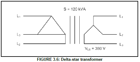
Given:
S = 120 kVA
VLS = 380 V
p.f. = 0,9 lagging
Determine the:
3.6.1 Secondary line current (3)
3.6.2 Secondary phase current (2)
3.6.3 Input power to the clinic (3)
3.7 Explain why the secondary winding of a step-down transformer has a thicker wire. (2)
[20]
QUESTION 4: THREE-PHASE MOTORS AND STARTERS
4.1 Refer to FIGURE 4.1 below and answer the questions that follow.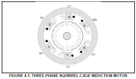
4.1.1 Name any TWO parts of the motor in FIGURE 4.1. (2)
4.1.2 Explain how the direction of rotation of this motor may be reversed. (2)
4.1.3 The stator of the motor may be connected in star or delta. Explain which connection would develop the greatest torque. (4)
4.2 State ONE advantage of a three-phase induction motor over a single-phase induction motor. (1)
4.3 Refer to FIGURE 4.3 below and answer the questions that follow.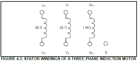
4.3.1 Consider the readings of the windings in FIGURE 4.3 and describe the fault. (2)
4.3.2 Explain the fault if the resistive reading between U2 and E taken with a megger (insulation resistance tester) is 0 Ω. (2)
4.3.3 Describe how the insulation test between windings must be carried out. (2)
4.4 A three-phase induction motor is connected to a 380 V/50 Hz supply. The motor has a synchronous speed of 1 500 r/min and a slip of 6%.
Given:
VL = 380 V
f = 50 Hz
slip = 6%
Answer the following questions:
4.4.1 Calculate the rotor speed. (3)
4.4.2 Explain why the frequency of the supply is important in the operation of motors that are connected to a load. (3)
4.5 A three-phase delta-connected motor delivers an output of 6,8 kW when connected to a 380 V/50 Hz supply. The motor has a power factor of 0,8 and an efficiency of 95%.
Given:
VL = 380 V
POUT = 6,8 kW
f = 50 Hz
p.f. = 0,8
ŋ = 95%
Calculate the following at full load:
4.5.1 Apparent power (3)
4.5.2 Reactive power (5)
4.6 FIGURE 4.6 below represents the control circuit of a sequence starter.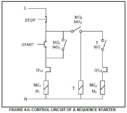
4.6.1 Name ONE practical situation where two motors may be started using the method in FIGURE 4.6. (1)
4.6.2 Describe what would happen if the contact MC1 N/O2 was faulty and permanently closed. (2)
4.6.3 Describe the starting sequence of the starter under normal conditions. (4)
4.6.4 The starter controls two different motors. Explain, with reasons, whether the control circuit caters for two motors that are rated differently. (4)
[40]
QUESTION 5: RLC
5.1 Describe the term impedance with reference to an RLC circuit. (2)
5.2 FIGURE 5.2 below shows the phasor diagram of a series RLC circuit. Answer the questions that follow.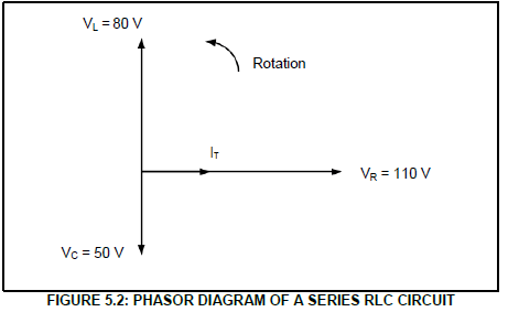
5.2.1 With reference to current and voltage, explain whether the circuit is inductive or capacitive. (3)
5.2.2 Describe how an increase in frequency will affect VL. (3)
5.2.3 Calculate the total voltage. (3)
VR = 110 V
VL = 80 V
VC = 50 V
5.3 The parallel circuit in FIGURE 5.3 below consists of a capacitor that draws a current of 4 A, an inductor that draws a current of 6 A and a resistor that draws a current of 5 A. The components are connected to a 240 V/50 HZ supply.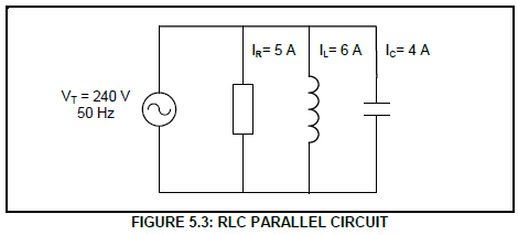
Given:
IR = 5 A
IL = 6 A
IC = 4 A
VT = 240 V
f = 50 Hz
Calculate the:
5.3.1 Total current (3)
5.3.2 Phase angle (3)
5.3.3 Inductive reactance (3)
[20]
QUESTION 6: LOGIC
6.1 State THREE advantages of a PLC system over a hardwired relay system. (3)
6.2 Name TWO languages used to program PLCs. (2)
6.3 Write the simplified Boolean equation for the expression below. Use a three-variable Karnaugh map. ![]() (10)
(10)
6.4 Refer to FIGURE 6.4 below and determine output F.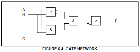 (6)
(6)
6.5 Simplify the following Boolean equation by using Boolean algebra: (6)
6.6 Refer to FIGURE 6.6 below and answer the questions that follow.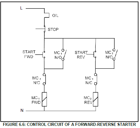
6.6.1 Draw the ladder logic diagram that will execute the same function in a PLC system. Use the same labelling given in FIGURE 6.6. (12)
6.6.2 Give ONE example where the circuit in FIGURE 6.6 may be used in an electrical application. (1)
[40]
QUESTION 7: AMPLIFIERS
7.1 Explain what an operational amplifier (op amp) is. (2)
7.2 State TWO advantages of using integrated circuits (such as op amps) over discrete components (circuits built with individual components). (2)
7.3 Describe how a differential amplifier works. (3)
7.4 Name the type of feedback found in the following circuits:
7.4.1 Amplifier circuits (1)
7.4.2 Oscillator circuits (1)
7.5 Explain the difference between positive feedback and negative feedback. (3)
7.6 Refer to FIGURE 7.6 below.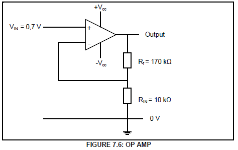
Calculate the:
7.6.1 Output voltage of the amplifier (3)
7.6.2 Voltage gain of the amplifier (3)
7.7 Name TWO applications of an inverting op amp. (2)
7.8 Give ONE application of a monostable multivibrator. (1)
7.9 Explain the main difference between a monostable multivibrator and a bi-stable multivibrator. (4)
7.10 Redraw the input waveforms below in the ANSWER BOOK and directly below them, on the same y-axis, draw the output waveforms of the identified circuits.
7.10.1 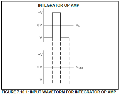 (3)
(3)
7.10.2 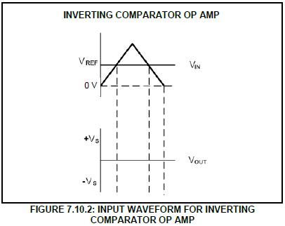 (3)
(3)
7.10.3 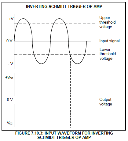 (3)
(3)
7.11 Redraw the input waveforms of an inverting summing op amp in FIGURE 7.11 below in the ANSWER BOOK and directly below them, on the same y-axis, draw the output waveform.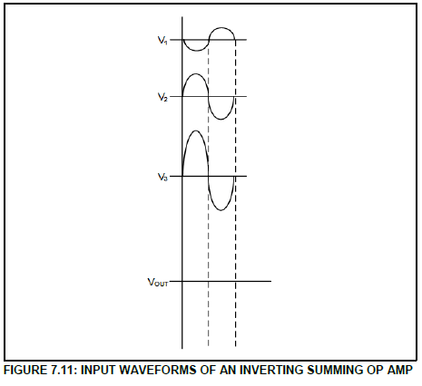 (3)
(3)
7.12 Refer to FIGURE 7.12 below.
An input voltage of 5 V is supplied to the input of an inverting amplifier circuit with an input resistor of 20 kΩ and a feedback resistor of 200 kΩ. The amplifier circuit is connected to a split-power supply.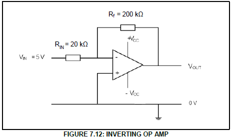
Calculate the:
7.12.1 Output voltage of the amplifier (3)
7.12.2 Gain of the amplifier (3)
7.13 State ONE application of a Schmidt trigger. (1)
7.14 A Hartley oscillator consists of two inductors with a total inductance of 27 mH and a capacitor of 47 μF. Calculate the resonant frequency of the oscillator.
Given:
LT = 27 mH
CT = 47 μF (3)
7.15 A RC phase-shift oscillator uses three RC networks. Assume that the resistor value and capacitor value are the same. The values of the resistors are 25 kΩ each and the values of the capacitors are 45 pF each. Calculate the resonant frequency of the oscillator.
Given:
R = 25 kΩ
C = 45 pF (3)
[50]
TOTAL: 200