ELECTRICAL TECHNOLOGY GRADE 12 MEMORANDUM - NSC PAST PAPERS AND MEMOS NOVEMBER 2017
Share via Whatsapp Join our WhatsApp Group Join our Telegram GroupELECTRICAL TECHNOLOGY
GRADE 12
NOVEMBER 2017
MEMORANDUM
NATIONAL SENIOR CERTIFICATE
INSTRUCTIONS TO THE MARKERS
- All questions with multiple answers imply that any relevant, acceptable answer should be considered.
- Calculations:
2.1 All calculations must show the formulae.
2.2 Substitution of values must be done correctly.
2.3 All answers MUST contain the correct unit to be considered.
2.4 Alternative methods must be considered, provided that the correct answer is obtained.
2.5 Where an incorrect answer could be carried over to the next step, the first answer will be deemed incorrect. However, should the incorrect answer be carried over correctly, the marker has to re-calculate the values, using the incorrect answer from the first calculation. If correctly used, the candidate should receive the full marks for subsequent calculations.
2.6 Markers should consider that learner answers may deviate slightly from the guideline, depending on how and where in the calculation rounding off was used. - This memorandum is only a guide with model answers. Alternative interpretations must be considered and marked on merit. However, this principle should be applied consistently throughout the marking session at ALL marking centres.
QUESTION 1: OCCUPATIONAL HEALTH AND SAFETY
1.1
1.1.1 Operating a machine or equipment without authorisation ✓
Failing to switch and lockout power when servicing a machine
Bypassing or removing safety guards
Wearing unsafe clothing or protective clothing
Playing around in the workshop
Using defective or faulty equipment (1)
1.1.2 Inadequate guarding of machines✓
Overcrowding in the workshop
Inadequate warning system
Excessive noise
Poor ventilation
Poor house keeping
Insufficient lighting (1)
1.2 Each member of the team will be given responsibility✓
Team members help each other to work honestly✓
Team members help each other to work safely✓
Team members help each other to work efficiently
Team work contributes towards the advancement of the team’s goal. (3)
1.3 Identify and apply pressure on✓ the pressure point next to the bleeding area✓
Lift and keep the bleeding area above the heart level
Use a clean sterile bandage to dress the bleeding area (2)
1.4 Any form of drug-abuse has the potential to reduce the ability✓ of an employee to work safely and cautiously ✓and these may lead to the amount of production been reduced or rejected due to substandard work. ✓ (3)
[10]
QUESTION 2: THREE-PHASE AC GENERATION
2.1 Neutral point is available when connected in star for distribution to consumers, ✓ allowing for both phase and line voltage (Two voltages are available)
Load distribution and phase balancing become possible ✓
Three phase supply systems are more versatile because they can be operated in star or in delta. ✓
Note to marker:
When listing advantages of a three phase motor, this will be deemed incorrect. (3)
2.2 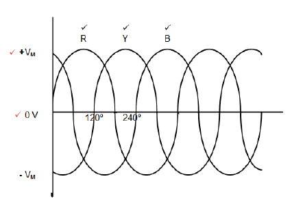
Note: Alternative correct labelling should be considered and marked on merit.
Correctly labelled phasor diagrams are acceptable. (5)
2.3 The two wattmeter method cannot determine if the power factor is leading or lagging. (1)
2.4
2.4.1S = √3VLIL
VL = S
√3 x IL
= 25 x 10 3
√3 x 38
= 379.84 V (3) ✓✓✓
2.4.2 VL = √3 x PH
VPH = VL
√3
VPH = 379.84
√3
= 219.31V (3)✓✓✓
2.4.3ZPH = VPH
IPH
= 219.31
38
=5.77Ω (3)✓✓✓
2.5 An improved power factor will lead to less wasted energy✓ thus leaving more power available to consumers. ✓
Power is utilised more effectively thus reducing generation cost.
Eskom will have more power available to supply consumers; with the improved power factors, there will be more power available on the national grid. (2)
[20]
QUESTION 3: THREE-PHASE TRANSFORMERS
3.1 The purpose of a transformer is to step down✓ or step up an alternating voltage. ✓
To transfer power from one ac circuit to another, with a change of voltage and corresponding current flow.
To isolate one circuit from another electrically. (2)
3.2 Copper losses ✓
I2R losses (1)
3.3 Air cooling ✓
Oil filled self-cooling ✓
Oil filled water cooling (2)
3.4 The transformer will overheat, ✓ the insulation between the windings will be damaged depending on the degree of heat✓ and in extreme cases this will lead to internal short circuit. ✓
Gas forming can occur which is in turn is highly combustible (3)
3.5 Used to distribute power to consumers✓ in the substation
It provides a neutral point to the four core end user system. ✓
To step down the voltage to a 380 V three-phase and 220 V single phase supply. (2)
3.6
3.6.1 S = √3VLIL
IL2 = S
√3VL
= 120000
√3 x 380
= 182.32A(3)✓✓✓
3.6.2 IPH = IL
=182.32 A(2)✓✓
3.6.3 P = √3VLIL cosθ
= √3 x 380 x 182.32 x 0.9
= 107999.32W
= 108kW (3)✓✓✓
Note: P=S x Cos θ is also correct
3.7 The secondary winding of a step down transformer has a thicker wire that will accommodate ✓ a higher current ✓in the secondary. (2)
[20]
QUESTION 4: THREE-PHASE MOTORS AND STARTERS
4.1
4.1.1 Stator ✓
Squirrel cage rotor ✓
Windings
Field Poles (2)
4.1.2 The connection to any TWO of the windings must be swapped. ✓ (2)
4.1.3 Delta connection will develop the greater torque. ✓
In delta the full line voltage will be connected across each winding. ✓
This increased voltage will give rise to an increased current.✓
This increased current will create stronger magnetic fields therefore leading to a greater output torque. ✓ (4)
4.2 A Three-phase induction motor requires less maintenance as it does not have as many parts as a single phase motor.✓
For the same size frame as a single phase motor it delivers higher torque. (1)
4.3
4.3.1 The resistive reading of the W winding is not close to the readings on the other two windings suggesting a fault.✓ Due to the high value the winding could indicate an open circuit / loose connection in that winding. ✓ (2)
4.3.2 A 0 Ω reading would indicate a short circuit✓ between earth and the winding. ✓ (2)
4.3.3 The megger (insulation resistance tester) must be set to the 1 000 V setting ✓
One lead must be connected to one of the windings and the other lead to the other winding. ✓
The reading must be taken and the test repeated between all three windings (2)
4.4
4.4.1 nR =nS (1-S)
nR = 1500(1-0.06)
nR = 1410r/min (3)✓✓✓
4.4.2 The frequency determines the speed✓ at which the motor will run✓
If the frequency of the supply changes the speed of the motor will change.
A change in speed of the motor will affect the load speed which could be detrimental to the load✓ (3)
4.5
4.5.1 = POUT
n x cosθ
= 6800
0.95 x 0.8
= 8947.36VA
=8.95kVA(3)✓✓✓
4.5.2 cosθ = 0.8
θ = cos-10.8
=36.87º
Q = S x sinθ
= 8947 x 0.6
= 5368.42 VAr
= 5.37kVAr (5)✓✓✓✓✓
4.6
4.6.1 Sewerage pumps ✓
Conveyer belt (1)
4.6.2 Without the start been depressed the timer contactor would be energised✓ starting motor two after the timer has timed through✓ (2)
4.6.3 When the start button is depressed MC1 is energised starting M1✓
MC1 N/O1 will now close and will hold the circuit in when the start is released✓
MC1 N/O2 will now close energising the timer contactor which will begin the timing process✓
The T N/O will close after a predetermined ✓time, energising MC M2 contactor switching M2 on ✓(4)
4.6.4 The control circuit is designed so that O/L's are connected in series✓with the contactor coil of each motor's contactor.✓ The two overloads may be set independently ✓which would protect each of the motors independently. ✓ (4)
[40]
QUESTION 5: RLC
5.1 Impedance is the total opposition offered to the flow of current✓ when a RLC circuit is connected across an alternating voltage supply.✓ (2)
5.2
5.2.1 VL is greater than VC which will result in a leading reactive voltage✓
The current IS will lag the voltage VS. ✓
Therefore the circuit is resistive inductive. ✓ (3)
5.2.2 If the frequency of the supply was increased the inductive reactance XL of the coil would increase✓as XL is directly proportional to the frequency of the supply.✓
If the inductive reactance of the coil increased the voltage across the coil VL would increase.✓ (3)
5.2.3 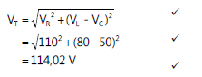 (3)
(3)
5.3
5.3.1 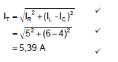 (3)
(3)
5.3.2 θ = cos-1IR
IT
θ = cos-1 5
5.39
= 21.93° (3)✓✓✓
5.3.3 XL = VT
IL
= 240
6
= 40Ω(3)✓✓✓
[20]
QUESTION 6: LOGIC
6.1 Reduced space✓
Use less energy✓
Less maintenance✓
More reliable
Faster response time
Flexible and Economical (3)
6.2 Ladder diagrams✓
Function blocks✓
Sequential function
Instructional list
Structured text. (2)
6.3 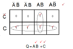 (10)
(10)
Note: Alternative labelling of the Karnaugh Map should be considered, thus influencing the placement and grouping of operands, however, the answer remains intact
Two Marks – Labelling
Five Marks – operands in K-Map
NO Marks for Grouping
One mark per operand in equation
One Mark for function in equation.
6.4 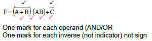 (6)
(6)
6.5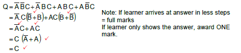 (6)
(6)
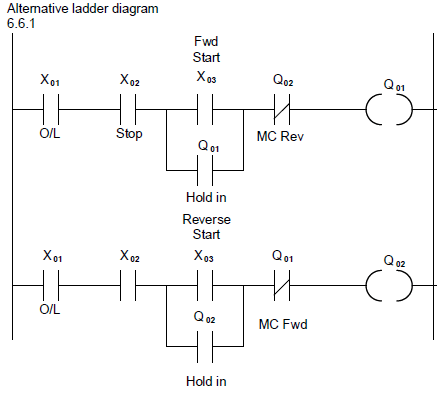
6.6
6.6.1 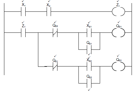
| Labels | Description |
| X1 | O/L |
| X2 | Stop |
| Z1 | Marker/flag |
| Q02 | Reverse MC2 |
| Q01 | Forward MC1 |
| X01 | Start forward |
| X02 | Start reverse |
(12)
6.6.2 Lifts ✓
Cranes
Conveyor belts (1)
[40]
QUESTION 7: AMPLIFIERS
7.1 An op amp is an integrated circuit✓ of a differential amplifier✓(2)
An op amp is an integrated circuit with a high voltage gain which consists of many components.
It is a circuit that has a very high open loop voltage gain.
7.2 Cheap to manufacture✓
Versatile✓
Easy to use
Contain a correctly assembled circuit allowing for fewer external components to be used (2)
7.3 A differential amplifier has two inputs and one output✓. When two inputs are supplied to the amplifier, it amplifies only the difference✓ between the two inputs✓
Note: If the learner uses actual values / refers to voltages/inputs and shows answer in arithmetic, the answer must be considered. (3)
7.4
7.4.1 Negative feedback✓ (1)
7.4.2 Positive feedback✓ (1)
7.5 Positive feedback: A portion of the output signal is fed back to the input✓ in phase with the input signal✓
Negative feedback: A portion of the output signal is fed back to the input 180º out of phase✓ with the input signal (3)
7.6
7.6.1 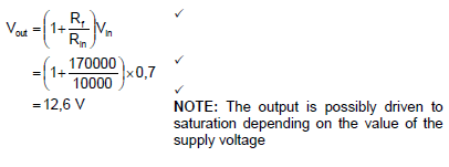 (3)
(3)
7.6.2
AV = V out
Vin
= 12.6
0.7
= 18 (3)✓✓✓
7.7 Audio amplifiers✓
Filters ✓
Oscillators
Controllers (2)
7.8 Pulse detector✓
Contact debouncer (1)
7.9 Bi-stable multi-vibrator remains in one state (Reset)✓until a new trigger sets it to a different state (Set) where it will remain.✓
The mono-stable multi-vibrator will change state (Set) when triggered✓. It will remain in this state for a set amount of time after which it will return to its original/stable state. (Reset)✓ (4)
7.10
7.10.1 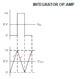 (3)
(3)
7.10.2 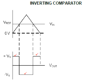 (3)
(3)
7.10.3 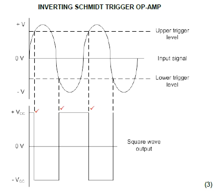
Note: If no input is drawn, care must be taken to the proportion and the placement of the output waveform when allocating marks.
7.11 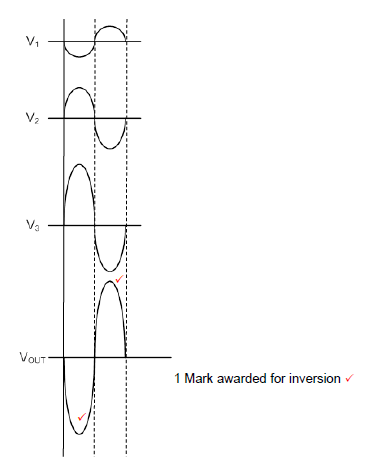 (3)
(3)
7.12
7.12.1 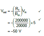 (3)
(3)
7.12.2 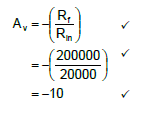 (3)
(3)
7.13 To clean noisy signals.✓
To implement another type of multi-vibrator.
Interfacing of analogue and digital signals.
Measuring of frequency in AC circuits.
Change any waveform into a square wave. (1)
7.14  (3)
(3)
7.15 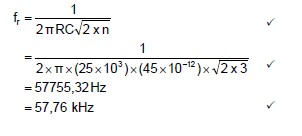 (3)
(3)
[50]
TOTAL: 200