CIVIL TECHNOLOGY GRADE 12 QUESTIONS - NSC PAST PAPERS AND MEMOS NOVEMBER 2017
Share via Whatsapp Join our WhatsApp Group Join our Telegram GroupCIVIL TECHNOLOGY
GRADE 12
NOVEMBER 2017
NATIONAL SENIOR CERTIFICATE
REQUIREMENTS:
- Drawing instruments
- A non-programmable pocket calculator
- ANSWER BOOK
INSTRUCTIONS AND INFORMATION
- This question paper consists of SIX questions.
- Answer ALL the questions.
- Answer each question as a whole. Do NOT separate subsections of questions.
- Start the answer to EACH question on a NEW page.
- Do NOT write in the margins of the ANSWER BOOK.
- You may use sketches to illustrate your answers.
- Write ALL calculations and answers in the ANSWER BOOK or on the attached ANSWER SHEETS.
- Use the mark allocation as a guide to the length of your answers.
- Make drawings and sketches in pencil, fully dimensioned and neatly finished off with descriptive titles and notes to conform to the SANS/SABS Code of
Practice for Building Drawings. - For the purpose of this question paper, the size of a brick should be taken as 220 mm x 110 mm x 75 mm.
- Use your own discretion where dimensions and/or details have been omitted.
- Answer QUESTIONS 1.7, 2.7, 2.11, 3.6, 3.7, 4.6, 5.2, 5.3, 6.1 and 6.2 on the attached ANSWER SHEETS using drawing instruments, where necessary.
- Write your CENTRE NUMBER and EXAMINATION NUMBER on every ANSWER SHEET and hand them in with your ANSWER BOOK, whether you have used them or not.
- Due to electronic transfer, drawings in the question paper are NOT to scale.
- Google Images was used as the source for all photographs and pictures.
QUESTION 1: CONSTRUCTION, SAFETY AND MATERIALS
1.1 FIGURE 1.1 below is an illustration of a worker on a building site. Describe TWO safety precautions that the worker should follow to prevent what is happening in the illustration.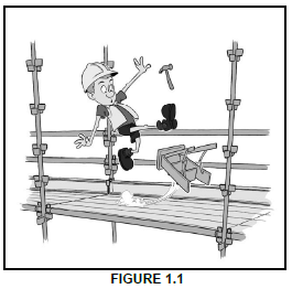 (2)
(2)
1.2 Explain why electric cables and the wires of power tools must be checked regularly. (1)
1.3 Give ONE reason why it is NOT safe to adjust a machine while the blade is in motion (turning). (1)
1.4 Name THREE accessories (equipment) that you need to conduct a slump test. (3)
1.5 Mixing concrete for small projects is usually done by hand. Recommend ONE method of mixing concrete for bigger projects. (1)
1.6 Choose a description from COLUMN B that matches an item in COLUMN A. Write only the letter (A–M) next to the question number (1.6.1–1.6.10) in the ANSWER BOOK, for example 1.6.11 N.
| COLUMN A | COLUMN B |
| 1.6.1 Plywood 1.6.2 Hardboard 1.6.3 Corrugated iron sheeting 1.6.4 Mild steel 1.6.5 PVC (polyvinyl chloride) 1.6.6 Gypsum board 1.6.7 Concrete 1.6.8 DPC (damp-proof course) 1.6.9 Powder coating 1.6.10 Varnish |
|
(10 x 1) (10)
1.7 FIGURE 1.7 on ANSWER SHEET 1.7 shows a drawing of a plan course of a corner (quoin) of a one-brick wall built in English bond.
1.7.1 Draw from the given plan course the next plan course of the corner. (4)
1.7.2 Print the title below the drawing. (1)
1.7.3 Describe the purpose of a queen closer in an English bond wall. (1)
1.8 Draw a line diagram of a lean-to roof in your ANSWER BOOK. Show the supporting walls and the roof. (2)
1.9 Ceilings should be finished off to preserve them.
1.9.1 Describe ONE type of equipment that can be used to apply paint to a ceiling. (1)
1.9.2 Give ONE reason for your answer to QUESTION 1.9.1. (1)
1.10 Name the components (materials) used to close the gap/opening between the following:
1.10.1 Floor covering and the wall (1)
1.10.2 Wall and the ceiling of a building (1)
[30]
QUESTION 2: ADVANCED CONSTRUCTION AND EQUIPMENT
Start this question on a NEW page.
2.1 Various options are given as possible answers to the following questions. Choose the answer and write only the letter (A–D) next to the question number (2.1.1–2.1.5) in the ANSWER BOOK, for example 2.1.6 C.
2.1.1 … foundation is used when the soil cannot support ordinary foundations.
- Strip
- Step
- Floating
- Pile (1)
2.1.2 During transportation of ready-mixed concrete, … can take place.
- desalination
- segregation
- curing
- shrinking (1)
2.1.3 … arches should be plastered.
- Gauged
- Rough
- Voussoir
- Intrados (1)
2.1.4 … is used to prevent concrete from clinging to formwork.
- Water
- Sanding sealer
- Thinners
- Oil (1)
2.1.5 … are used to keep the main bars of the reinforcement of a column together.
- Spacers
- Shear bars
- Stirrups
- Wall ties (1)
2.2 FIGURE 2.2 below is a photograph of an instrument used for surveying.
2.2.1 Identify the instrument in FIGURE 2.2 above. (1)
2.2.2 Describe ONE function of this instrument. (1)
2.2.3 Name the part on which this instrument must be mounted. (1)
2.2.4 Name the accessory that is used with the instrument to get a reading. (1)
2.2.5 Describe why the instrument should be stored in its original casing after being used. (1)
2.3 FIGURE 2.3 below is an illustration of a precast floor slab. Study the illustration and answer the questions that follow.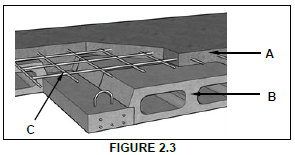
2.3.1 Name the type of floor construction that is illustrated in FIGURE 2.3 above. (1)
2.3.2 Identify A, B and C. (3)
2.3.3 Give ONE reason why you would rather use the type of floor construction in FIGURE 2.3, than an in situ cast suspended floor. (1)
2.4 FIGURE 2.4 below shows a sectional view of a cavity wall.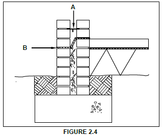
2.4.1 Identify A and B. (2)
2.4.2 Name ONE other place in a building where you would find material B. (1)
2.4.3 State ONE advantage of a cavity wall. (1)
2.5 Explain the terms intrados and extrados, as used in arches. (2)
2.6 FIGURE 2.6 below shows equipment used to test concrete.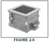
2.6.1 Identify the equipment shown in FIGURE 2.6 above. (1)
2.6.2 Name ONE other piece of equipment that must be used with this equipment when conducting the concrete test. (1)
2.6.3 Name the type of test conducted with this equipment. (1)
2.6.4 Explain the purpose of this test. (1)
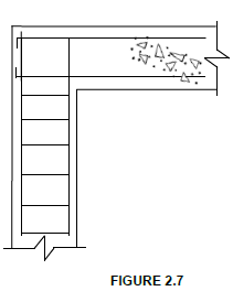
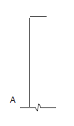
2.7 FIGURE 2.7 on ANSWER SHEET 2.7 is a sketch of a simple supported beam with a main bar and an anchor bar attached to a column with reinforcement in position. Complete the sketch on ANSWER SHEET 2.7 by drawing the following steel reinforcement in place:
- Shear bar
- Stirrups/Binders in the rest of the beam (2)
2.8 FIGURE 2.8 below shows two types of reinforcing bars that can be used for reinforcing concrete. Study the figure and name EACH of the reinforcing bars. Write down the answer next to the question number (2.8.1–2.8.2) in the ANSWER BOOK.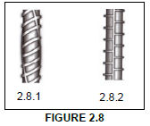 (2)
(2)
2.9 FIGURE 2.9 below shows the formwork of a square column. Study the figure and answer the questions that follow.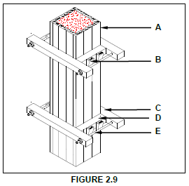
2.9.1 Name ONE material that A can be made of. (1)
2.9.2 Identify B to E. (4)
2.9.3 Predict what will happen if E is not installed. (1)
2.10 State ONE disadvantage of a dry wall. (1)
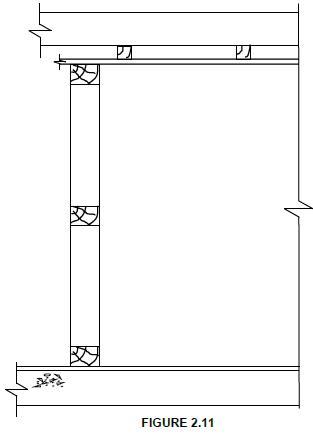
2.11 FIGURE 2.11 on ANSWER SHEET 2.11 shows a part of a dry-wall construction with a timber frame. Complete the drawing on ANSWER SHEET 2.11 by adding the following in good proportion:
- Cladding
- The moulding at the ceiling and the wall
- The moulding at the floor and the wall (3)
2.12 Name ONE type of pile foundation. (1)
[40]
QUESTION 3: CIVIL SERVICES
Start this question on a NEW page.
3.1 FIGURE 3.1 below shows a water trap that is used in civil services.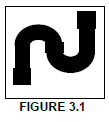
3.1.1 Identify the water trap above. (1)
3.1.2 Explain the purpose of a water trap. (1)
3.2 State TWO factors that determine the temperature of the water in a solar heater. (2)
3.3 You are a plumber and must answer the following questions from a client:
3.3.1 Name the part in an electric geyser that is used to warm up water. (1)
3.3.2 Explain why the cold water inlet is mounted at the bottom of the geyser and the hot water outlet is mounted at the top of the geyser. (2)
3.3.3 Name the component that is installed for safety purposes to prevent the geyser from bursting when the water becomes too hot. (1)
3.4 FIGURE 3.4 below is a photograph of a storm-water grid on a road. Study the photograph and answer the questions that follow.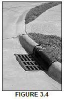
3.4.1 Explain the function of the grid. (1)
3.4.2 State ONE consequence if the grid is blocked. (1)
FIGURE 3.1
3.5 Water supply is a basic necessity of life. Owing to a lack of municipal services, an increasing number of people are investing in borehole systems.
Name TWO mechanical methods that may be used to obtain water from a borehole. (2)
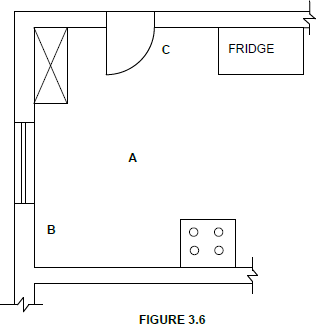
3.6 FIGURE 3.6 on ANSWER SHEET 3.6 shows an incomplete floor plan of a kitchen. Complete the drawing on ANSWER SHEET 3.6 by drawing the symbols for the following electrical fittings and wiring:
3.6.1 Fluorescent light at A (2)
3.6.2 Distribution board at B (2)
3.6.3 Double-pole one-way light switch at C (2)
3.6.4 Electrical wiring from C to A (2)
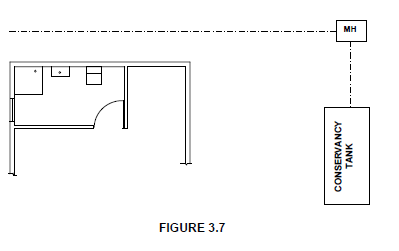
3.7 FIGURE 3.7 on ANSWER SHEET 3.7 shows the incomplete layout of a one-pipe sewerage system connected to a conservancy tank. Sanitary fixtures have been indicated with symbols. Study the drawing and draw the following on ANSWER SHEET 3.7 with the correct symbols. All regulations and design principles of a good sewerage system must be adhered to.
- 1 x rodding eye
- 1 x gully
- 1 x ventilation pipe
- 2 x branch pipes
- 2 x inspection eyes
- Any THREE abbreviations for sewerage components (10)
[30]
QUESTION 4: QUANTITIES, MATERIALS AND JOINING
Start this question on a NEW page.
4.1 Below are photographs of fasteners that are used on building sites. Write down the name and ONE use of EACH fastener next to the question number (4.1.1–4.1.3) in the ANSWER BOOK. 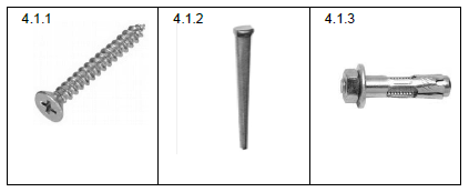 (6)
(6)
4.2 Name ONE fastener that you will use when joining purlins to rafters. (1)
4.3 State TWO advantages of nails over screws. (2)
4.4 Name ONE pipe that can be joined by means of a compression joint. (1)
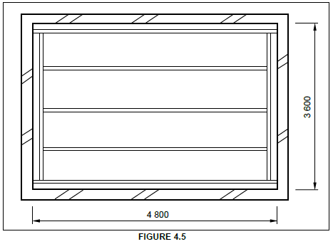
4.5 FIGURE 4.5 on the next page shows the brandering layout of a ceiling construction and the four walls. Study the drawing and complete the incomplete cutting list. Write down the answer next to the question number (4.5.1–4.5.7) in the ANSWER BOOK.
Use the following specifications to answer the question:
- Ceiling board: 6,4 mm x 900 mm x 3 600 mm
- Brandering: 38 mm x 38 mm
- Brandering is placed 75 mm away from each wall
- Cornices: 75 mm x 75 mm
- Wooden cover strips: 45 mm x 10 mm (7)
| CUTTING LIST FOR CEILING | |||||||
| MEMBER | QUANTITY | UNIT | LENGTH | WIDTH | THICKNESS | TOTAL LENGTH | MATERIAL |
| Long-wall brandering/ Battens | 2 | mm | 4800 | 38 | 4.5.1 | 9600 | SA pine |
| Intermediate brandering/ Battens | mm | 4574 | 38 | 38 | 13722 | SA pine | |
| Short-wall brandering/ Battens | 2 | mm | 4.5.3 | 38 | 38 | 6748 | SA pine |
| Ceiling boards | 6 | mm | 4.5.4 | 900 | 6.4 | 21600 | Gypsum board |
| Cornices: Long wall | 2 | mm | 4800 | 75 | 75 | 4.5.5 | Gypsum board |
| Cornices: Short wall | 2 | mm | 4.5.6 | 75 | 75 | 7200 | Gypsum board |
| Wooden cover strips | 5 | mm | 3450 | 45 | 10 | 4.5.7 | SA pine |
4.6 FIGURE 4.6 below shows the floor plan of a room. You must install ceiling boards and skirtings in this room.
SPECIFICATIONS:
- Outside measurements of the room: 7 000 mm x 4 000 mm
- The external walls are one-brick walls (220 mm)
- Size of sliding door: 3 000 mm wide x 2 000 mm high
- Size of ceiling boards: 4 200 mm x 1 200 mm
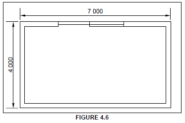
Use ANSWER SHEET 4.6 and answer the following questions:
4.6.1 Calculate the inside area of the room in square metres (m²). Round off your answer to TWO decimal places. (6)
4.6.2 Calculate the area of ONE ceiling board in square metres (m²). (3)
4.6.3 Calculate the length of the skirting required in metres (m). Ignore the reveals. (4)
[30]
QUESTION 5: APPLIED MECHANICS
Start this question on a NEW page.
5.1 FIGURE 5.1 below shows a shaped lamina. All dimensions are in millimetres.
Study the lamina and calculate the centroid of the lamina from A-A. Round off your answer to TWO decimal places.
HINT: Use the formula on the FORMULA SHEET.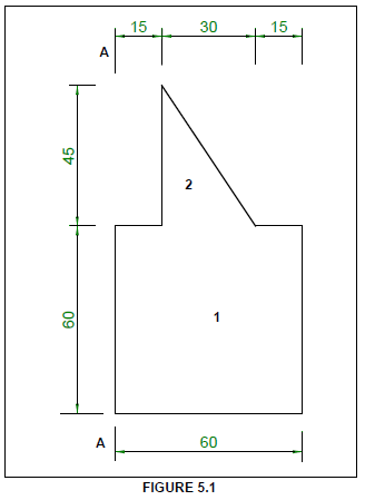 (10)
(10)
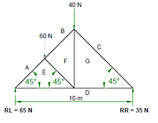
5.2 FIGURE 5.2 shows the space diagram of a truss with two point loads and a span of 10 metres.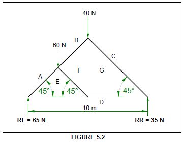
5.2.1 Use ANSWER SHEET 5.2 and develop and draw a vector diagram to determine the nature and magnitude of the forces in the members (parts) of the truss graphically.
Use scale 1 mm = 1 N. (8)
5.2.2 Use the information in the space diagram and vector diagram and complete the table on ANSWER SHEET 5.2. (4)
5.3 FIGURE 5.3 below shows the space diagram of a beam with a span of 12 metres, with three point loads and a uniformly distributed load. Study the diagram and answer the questions that follow.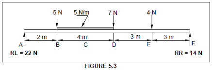
5.3.1 Convert the uniformly distributed load to a point load and write down the value of the converted point load. (1)
5.3.2 Determine the distance of the converted uniformly distributed load that now is a point load from RR. (1)
5.3.3 Determine the distance of the converted uniformly distributed load that now is a point load from RL. (1)
5.3.4 The value of the bending moments at A = 0 Nm, B = 44 Nm, C = 68 Nm, D = 72 Nm, E = 42 Nm and F = 0 Nm. Use all the available information and draw the bending moment diagram on ANSWER SHEET 5.3. Use scale 1 mm = 1 Nm. (5)
[30]
QUESTION 6: GRAPHICS AND COMMUNICATION
6.1 FIGURE 6.1 below shows the south elevation of a proposed dwelling.
Study the drawing and complete the table on ANSWER SHEET 6.1.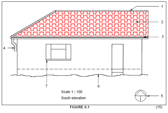 (15)
(15)
6.2 FIGURE 6.2 below shows the floor plan of a one-bedroom house.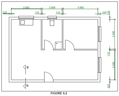
On ANSWER SHEET 6.2, draw to scale 1 : 20 a vertical sectional view on section line B–B to show the top part of the superstructure wall and a little more than half of the SA (Howe) roof truss with closed eaves and an overhang of 500 mm. Start your drawing from the point given on the answer sheet.
SPECIFICATIONS:
- Wall: 220 mm, plastered on both sides
- Plaster: 20 mm thick
- Wall plate: 114 mm x 38 mm
- Span of roof: 4 110 mm
- SA (Howe) roof truss with closed eaves
- Slope of roof: 30°
- Tie beam: 114 mm x 38 mm
- Rafters: 114 mm x 38 mm
- King post: 114 mm x 38 mm
- Queen post: 114 mm x 38 mm
- Strut: 114 mm x 38 mm
- Fascia board: 228 mm x 32 mm
Closed eaves:
- Hangers: 38 mm x 38 mm
- Bearers: 38 mm x 38 mm
- Fibre-cement ceiling boards/Soffit boards
Print the title below the drawing.
Show any THREE labels on the drawing. (25)
[40]
TOTAL: 200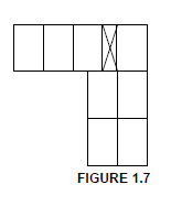
| ASSESSMENT CRITERIA | MARK | CANDIDATE'S MARK |
| Stretcher course | 1 | |
| Corner brick | 1 | |
| Queen closer | 1 | |
| Header course | 1 | |
| TOTAL | 4 |
| ASSESSMENT CRITERIA | MARK | CANDIDATE'S MARK |
| Shear bar drawn correctly | 1 | |
| Stirrups drawn correctly | 1 | |
| TOTAL | 2 |
| ASSESSMENT CRITERIA | MARK | CANDIDATE'S MARK |
| Cladding drawn correctly | 1 | |
| Moulding at ceiling and wall drawn correctly | 1 | |
| Moulding at floor and wall drawn correctly | 1 | |
| TOTAL | 3 |
| ASSESSMENT CRITERIA | MARK | CANDIDATE'S MARK |
| Fluorescent light | 2 | |
| Distribution board | 2 | |
| Double-pole light switch (one-way) | 2 | |
| Electrical wiring | 28 | |
| TOTAL |
| ASSESSMENT CRITERIA | MARK | CANDIDATE'S MARK |
| Rodding eye | 1 | |
| Gully | 1 | |
| Ventilation pipe | 1 | |
| Branch pipes 45° | 2 | |
| Inspection eyes | 2 | |
| Any THREE abbreviations | 3 | |
| TOTAL | 10 |
ANSWER SHEET 4.6
Complete your answers in the spaces indicated with _____________.
| A | B | C | D |
| Inside measurements of room: | |||
| Long walls = ______ – 2/_____ | |||
| = ______ | |||
| Short walls = ______ – 2/_____ | |||
| = ______ | |||
| (4) | |||
| 1/ | _____ | Inside area of room: | |
| _____ | _____ m² | ||
| (2) | |||
| Area of one ceiling board: | |||
| 1/ | _____ | One board is ______ mm x ______ mm | |
| _____ | _____ m² | (3) | |
| Length of skirting: | |||
| = | |||
| = | |||
| = | |||
| (4) |
| MEMBER | NATURE | MAGNITUDE |
| AE | ||
| DG |
Tolerance of 1 N to either side
(8)
ANSWER SHEET 5.3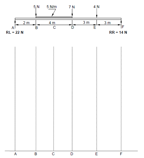
ANSWER SHEET 6.1
| NO. | QUESTIONS | ANSWERS | MARKS |
| 1 | Name the title of the drawing | 1 | |
| 2 | Identify number 1. | 1 | |
| 3 | Identify number 2 | 1 | |
| 4 | Identify number 3 | 1 | |
| 5 | Identify number 4 | 1 | |
| 6 | Identify number 5 | 1 | |
| 7 | Identify number 6 | 1 | |
| 8 | Identify number 7 | 1 | |
| 9 | Name the type of roof on the eastern side of the house. | 1 | |
| 10 | Name the type of roof on the western side of the house. | 1 | |
| 11 | Name the material that can be used for the fascia board? | 1 | |
| 12 | On how many sides of the building will you find fascia boards? | 1 | |
| 13 | Draw the top view (roofline) of the roof for the elevation indicated in FIGURE 6.1 in the column alongside . | 3 | |
| TOTAL | 15 |
| ASSESSMENT CRITERIA | MARKS | LM |
| Correctness of drawing | 3 | |
| External wall | 1 | |
| Symbol for wall | 1 | |
| Plaster | 2 | |
| Wall plate | 1 | |
| Tie beam | 1 | |
| Rafters | 2 | |
| Strut | 1 | |
| Queen post | 1 | |
| King post | 1 | |
| Fascia board | 1 | |
| Hanger | 1 | |
| Bearer | 1 | |
| Fibre cement ceiling board | 1 | |
| Any THREE labels | 3 | |
| Print title | 1 | |
| Application of scale One or two incorrect = 3 Three or four incorrect = 2 More than five incorrect = 1 No measurement correct = 0 | 3 | |
| Total | 25 |
IMPORTANT ABBREVIATIONS
| SYMBOL | DESCRIPTION | SYMBOL | DESCRIPTION | SYMBOL | DESCRIPTION |
| c | Centroid | b | Breadth/Width | r | Radius |
| ℓ | Length | s | Side | A | Area |
FORMULAE
| AREA OF | FORMULA (in words) | FORMULA (in symbols) | FORMULA FOR THE POSITION OF CENTROIDS | |
| X-axis | Y-axis | |||
| Square | side x side | s x s | s 2 | s 2 |
| Rectangle | length x breadth | ℓ x b | ℓ 2 | b 2 |
| Right-angled triangle | ½ x base x height | ½b x h | b 3 | h 3 |
| Equilateral triangle/ Isosceles triangle | ½ x base x height | ½b x h | b 2 | h 3 |
Position of centroid = (A1 x d) ± (A2 x d)
Total area
OR
Y = ΣAy
ΣA
OR
X = ΣAx
ΣA