ELECTRICAL TECHNOLOGY GRADE 12 MEMORANDUM - NSC PAST PAPERS AND MEMOS FEBRUARY/MARCH 2016
Share via Whatsapp Join our WhatsApp Group Join our Telegram GroupNATIONALSENIOR CERTIFICATE
GRADE 12
ELECTRICAL TECHNOLOGY
MEMORANDUM
FEBRUARY/MARCH 2016
INSTRUCTIONS TO THE MARKERS
- All questions with multiple answers imply that any relevant, acceptable answer should be considered..
- Calculations:
2.1 All calculations must show the formulae.
2.2 Substitution of values must be done correctly.
2.3 All answers MUST contain the correct unit to be considered.
2.4 Alternative methods must be considered, provided that the correct answer is obtained.
2.5 Where an incorrect answer could be carried over to the next step, the first answer will be deemed incorrect. However, should the incorrect answer be carried over correctly, the marker has to re-calculate the values, using the incorrect answer from the first calculation. If correctly used, the candidate should receive the full marks for subsequent calculations. - This memorandum is only a guide with model answers. Alternative interpretations must be considered and marked on merit. However, this principle should be applied consistently throughout the marking session at ALL marking centres.
QUESTION 1: OCCUPATIONAL HEALTH AND SAFETY
1.1 Unsafe conditions include:
- Inadequate guards around machinery. ✓
- No eye protection goggles in the workshop and around the bench grinder.
- Loose and dangerous components on moving machinery. (1)
1.2 An unsafe action is an action performed by a person/worker that could cause:
- Injury to him/herself or his/her colleagues✓
- Cause damage to tools and equipment
- Render a workplace unsafe
- Lead to loss of income to the employer (2)
1.3 Protocol to follow when discovering a person experiencing electrical shock is:
- Do not touch the victim with bare hands until the supply is turned off. ✓
- Switch off the supply. ✓
- Call a teacher or medical person for help. ✓
- If the electricity cannot be switched off and the victim is still in contact with it push the wire away with an insulated object. ✓(4)
1.4 Productivity is an important work ethic to assist the growth of South Africa's economy due to the following reasons:
- Safe working procedures are more productive as less time is lost due to injuries and downtime related to accidents. ✓
- Efficient working methods lead to less use of raw materials, thus increasing profits. ✓
- Good ergonomics lead to cleaner and safer work environments and promotes worker satisfaction and morale. ✓
- Workers with a high morale and a good safety record tend to follow instructions more precisely and enact safe working procedures.
- Effective monitoring and reporting systems lead to better quality assurance of products, thus placing a better product in the market within a shorter time frame, thus promoting productivity. (3)
[10]
QUESTION 2: THREE-PHASE AC GENERATION
2.1 A Kilo-watt hour meter ✓ (1)
2.2 Two advantages of three-phase systems over single-phase systems are:
- 3φ can be operated in star or delta. ✓
- Three-phase systems can supply both three-phase and single-phase installations of power✓
- In generators and motors, for the same size frames, three-phase machines delivers more power than single-phase machines (2)
2.3
(5)
Note to markers:
No additional marks are awarded for the manipulation of the formulae. Manipulation is shown to illustrate how the formula was derived.
2.4
2.4.1 S = √3 VL IL
VL= S ✓
√3 × IL
= 20000 ✓
√3 × 25
= 461.88 A ✓ (3)
2.4.2 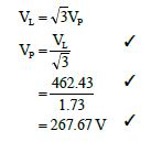 (3)
(3)
2.5
2.5.1 PT = P1 + P2 ✓
= (8+4)kW ✓
= 12 kW✓ (3)
2.5.2 P = √3 VL IL Cosθ
IL= P ✓
√3 × VLCosθ
= 12000 ✓
√3 × 380 × 0.8
=22.79 A ✓ (3)
[20]
QUESTION 3: THREE-PHASE TRANSFORMERS
3.1 By laminating and insulating the laminations of the core of the transformer.✓ (1)
3.2 Two similarities between single phase and three-phase are:
- Both have the same functional operations✓
- Transformers are used to step down or step up the supply voltage✓
- Both can have either the closed core type or shell core type
- No electrical connections between primary and secondary windings, with the exception of the autotransformer. (2)
3.3 Two factors that may cause excessive heating in a transformer are:
- Insufficient ventilation✓
- Constant overloading✓
- Loose connections
- Ineffective tap-changer contacts
- Impure/carbonized/insufficient transformer oil (2)
3.4 Applications of delta-star connected transformers in power distribution systems are:
- Single and three-phase supply to Commercial sites ✓
- Three-phase supply to Industrial areas ✓
- Single and three-phase supply to domestic installations
- Single and three-phase supply to agricultural installations
- Three-phase supply to other substations (transformers) in a ring-fed supply network. (2)
3.5 The function of a transformer is to 'step down' ✓ or to 'step up' ✓ (transform) the voltage ✓in a distribution network to the required value. (3)
3.6
3.6.1 VL = VPH ✓
∴VPH= 6.6 kV ✓ (2)
3.6.2 IL = IP
∴IP= 30A ✓ (2)
3.6.3 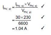 (3)
(3)
3.6.4 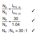 (3)
(3)
[20]
QUESTION 4: THREE-PHASE MOTORS AND STARTERS
4.1 Applications of three-phase motors include:
- pumps✓
- lifts
- cranes (1)
4.2 Advantages of a three-phase over single-phase motors:
- For the same size frame a three-phase motor delivers more power ✓
- Three-phase motors are self-starting ✓
- More robust✓
- Simple construction (3)
4.3
4.3.1 At start motors draw more than the motors rated current.✓ This may lead to unnecessary tripping of the motor ✓ and the increased current at start causes wear on switch gear. ✓ (3)
4.3.2 The motor is started in the star mode which reduces✓ the voltage across each phase of the motor as in star VPH = √3 VL. ✓ As the voltage across each phase is reduced, the current in each phase will also be reduced. ✓ (3)
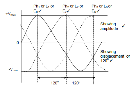
4.4 The operation of three-phase squirrel cage induction motor:
- Three-phase supply is such that the peak voltage of each phase is reached at 120o intervals.
- When a squirrel cage motor is connected across a three phase alternating supply, alternating current will flow in the respective stator windings.✓
- As a result the alternating current will set up a magnetic field in and around the respective stator windings.✓
- The stator windings are however spaced 120o apart around the axis of the motor.
- The result is that the magnetic field has a rotating maximum flux density as the peak in each winding is reached at a 120o interval, resulting in a rotating magnetic field.✓
- A squirrel cage rotor consists of cage like conductors bound electrically with a short circuit ring at each end.✓
- The rotating magnetic field will sweep across the rotor conductors of the squirrel cage rotor.✓
- As the magnetic field sweeps over the rotor conductors, the magnetic flux will cut/cross the rotor conductors.✓
- Faraday's law determines that an EMF will be induced in the rotor windings due to the sweeping action of the rotating magnetic field
- Lenz's Law will determine that the induced current will be such that its force will oppose the inducing action (from the stator), thus establishing a repelling force between the stator and rotor (due to the opposing magnetic fields), thus forcing the rotor into rotation.
- When the speed of the rotor approaches the speed of the rotating magnetic field (synchronic speed), the inducing action is reduced and the rotor tends to slow down. The result is that the rotor rotates at a speed lower than that of the rotating magnetic field (synchronic speed)✓ (7)
4.5
4.5.1 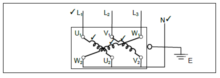 (5)
(5)
Coil 1:U1 – U2 ✓
Coil 2: V1 – V2✓
Coil 3: W1 – W2✓
L1 , L2, L3 – 3 Phase specified✓
N: Star is specified✓
E – Not requested in the question
4.5.2 The reading on the meter should be of a high resistive value, ✓ more than 1 MΩ, this will indicate that there is no electrical connection between the windings ✓ showing sound/good insulation. ✓ (3)
4.5.3 A low resistance reading will indicate that there is electrical connection between the winding and earth.✓ This will indicate any electrical fault✓ that may lead to an operator being shocked in the motor is energised.✓ (3)
4.6 Pole pairs = 60 × f ✓
NS
= 60 × 50 ✓
600
= 5 ✓ (3)
4.7
4.7.1 S = √3 VL IL ✓
= √3 × 380 16 ✓
= 10.53 kVA ✓ (3)
4.7.2 η =100%
P = S × Cosθ ✓
= 10.53 × 0.85 ✓
= 8.95kW ✓ (3)
4.7.3 ![]()
P = Pi × η ✓
= 8.95 × 0.9 ✓
= 8.06 kW ✓ (3)
[40]
QUESTION 5: RLC
5.1 Factors influencing the capacitive reactance are:
- Value of capacitance✓
- Frequency of the supply✓ (2)
5.2 Reactance is the opposition of the specific reactive component✓ to the flow of current in AC circuits
Impedance is the total opposition✓ offered to the flow of current in an AC circuit which contains resistive and reactive components (2)
5.3 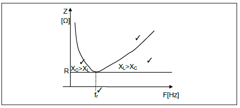 (4)
(4)
5.4  (3)
(3)
5.5 5.5.1 XC = 1
2πƒC
= 1
2π × 50 × 47 × 10-6
= 67,73Ω (3)
5.5.2 XL = 2πƒL✓
= 2π × 50 × 400 × 10-3 ✓
= 125,66Ω ✓ (3)
5.5.3 ƒr = 1 ✓
2π√LC
= 1 ✓
2π√400 × 10-3 × 47 × 10-6
= 36.71Hz ✓ (3)
[20]
QUESTION 6: LOGIC
6.1 Advantages of a PLC over a hardwired systems are:
- Reduced space. PLCs are solid state devices and are compact and small compared to hard wire logic. ✓
- Less maintenance PLCs have error diagnostic units making it easy to trouble shoot. ✓
- Faster response time it can process thousands of items a second. (2)
6.2 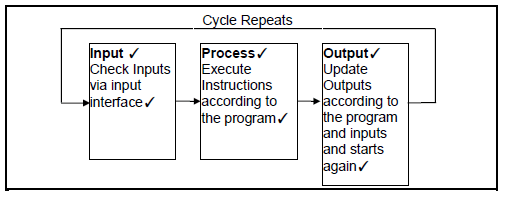 (6)
(6)
6.3 Output devices that can be used with a PLC are:
- Motor contactor ✓
- indicator lamps ✓
- relays
- switches (2)
6.4 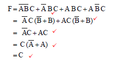 (5)
(5)
6.5 PLCs could be programmed using the following methods:
- Ladder diagrams✓
- Function blocks✓
- Sequential functions✓
- Charts
- Instructional list
- Structured text (3)
6.6.1 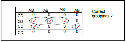 (6)
(6)
6.6.2 ![]() (3)
(3)
6.7
6.7.1 Sequence ✓starter with a time delay circuit✓
Note to markers:
The circuit cannot be star delta starter as there is no lockout function included in the circuit. (2)
6.7.2 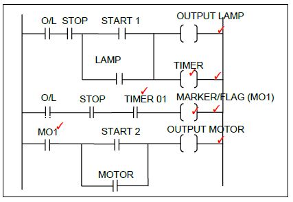 (8)
(8)
Note to markers:
− The candidate may use inverse functions (simulating real world NO and NC switches) in the ladder circuit, which must be considered. Should it function correctly marks are to be awarded to the candidate.
− Note that some labels may differ from that of the learner.
− Please check that the learner utilises labelling consistently throughout the answer.
6.7.3 PLC's allow for the use of markers as the number of operands✓ that can be placed in a rung✓ of the Ladder program is limited✓ due to hardware design constraints.
A marker/flag is a function of PLC programming that can be used as a placeholder, or a subroutine which in turn simplifies the ladder program. (3)
[40]
QUESTION 7: AMPLIFIERS
7.1 Characteristics of ideal op-amps are:
- Open-loop voltage gain AV = infinite✓
- Input impedance Zin = infinite✓
- Output impedance Z0 = zero
- Bandwidth = infinite
- Unconditional stability
- Differential inputs, i.e. two inputs
- Infinite common-mode rejection (2)
7.2 The bandwidth is the range of frequencies ✓within which an amplifier can amplify without distorting the output signal (retain linearity) ✓ or losing gain.✓ (3)
7.3 Positive feedback is obtained when the output signal ✓of an amplifier circuit is fed back to the input of the circuit. ✓ When the signal is fed back to the input, it is in phase with the input signal, thus added to the input signal. ✓ (3)
7.4 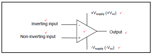 (6)
(6)
7.5
7.5.1 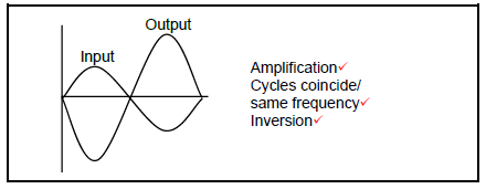 (3)
(3)
7.5.2 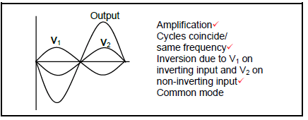 (3)
(3)
7.6 Advantages of using negative feedback are:
- Bandwidth is increased. ✓
- Level of noise (hiss) is decreased. ✓
- Gain is decreased.
- Deformation of the input signal is reduced. (2)
7.7
7.7.1 Non inverting op-amp (1)
7.7.2 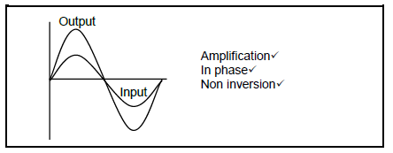 (3)
(3)
7.7.3 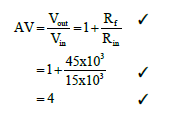 (3)
(3)
7.7.4 Vout = AV × Vin ✓
= 4 × 2.5 ✓
= 10V ✓ (3)
7.8 The a-stable multivibrator can be used as a:
- Tone generator ✓
- Clock pulse generator✓
- Square wave generator
- Fake alarm circuit if used with two LED's(2)
7.9 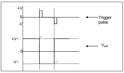 (4)
(4)
7.10
7.10.1 Positive feedback ✓ (1)
7.10.2
Sine wave generator✓
Tone Oscillator
Buzzer driver (1)
7.10.3 fRC = 1 ✓
2π√6RC
= 1 ✓
2π√6 ×15 × 150 × 10-9
= 43.31Hz ✓ (3)
7.11
7.11.1 Timing circuit (1)
7.11.2 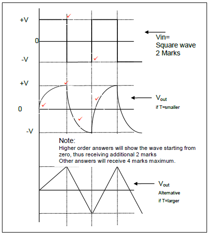 (6)
(6)
[50]
TOTAL: 200