ELECTRICAL TECHNOLOGY GRADE 12 QUESTIONS - NSC PAST PAPERS AND MEMOS FEBRUARY/MARCH 2016
Share via Whatsapp Join our WhatsApp Group Join our Telegram GroupNATIONALSENIOR CERTIFICATE
GRADE 12
ELECTRICAL TECHNOLOGY
FEBRUARY/MARCH 2016
INSTRUCTIONS AND INFORMATION
- This question paper consists of SEVEN questions.
- Answer ALL the questions.
- Sketches and diagrams must be large, neat and fully labelled.
- Show ALL calculations and round off answers correctly to TWO decimal places.
- Number the answers correctly according to the numbering system used in this question paper.
- You may use a non-programmable calculator.
- Show the units for all answers of calculations.
- A formula sheet is attached at the end of this question paper.
- Write neatly and legibly.
QUESTION 1: OCCUPATIONAL HEALTH AND SAFETY
1.1 Name ONE unsafe condition that may result in an injury in an electrical technology workshop. (1)
1.2 Define the term unsafe action with reference to an electrical technology workshop. (2)
1.3 State FOUR steps, in order of priority, that must be adhered to when helping a person who is a victim of an electrical shock in an electrical technology workshop. (4)
1.4 Briefly explain why productivity is considered an important work ethic in the South African industrial context. (3)
[10]
QUESTION 2: THREE-PHASE AC GENERATION
2.1 Name the instrument that is used to measure electrical energy. (1)
2.2 State TWO advantages of three-phase systems over single-phase systems. (2)
2.3 Draw a neatly labelled sketch representing the voltage waveforms of a three-phase AC generation system. (5)
2.4 A three-phase star-connected balanced load is supplied by a three-phase generator. The generator supplies 20 kVA at a current of 25 A.
Given:
Il = 25 A
S = 20 kVA
Calculate the:
2.4.1 Line voltage (3)
2.4.2 Phase voltage (3)
2.5 In a three-phase supply system the two-wattmeter method was used to measure the input power to an inductive load which has a power factor of 0,8. The values indicated on the instruments are 8 kW and 4 kW respectively. The line voltage is 380 V.
Given:
P1=8 kW
P2=4 kW
Cos Ɵ=0,8
Vl=380 V
Calculate the:
2.5.1 Total input power (3)
2.5.2 Line current (3)
[20]
QUESTION 3: THREE-PHASE TRANSFORMERS
3.1 State how eddy currents may be limited in the iron core of a transformer. (1)
3.2 Name TWO similarities between a single-phase transformer and a three-phase transformer. (2)
3.3 State TWO factors that may cause excessive heating in a transformer. (2)
3.4 Name TWO applications of a delta-star-connected distribution network transformer. (2)
3.5 Explain the function of a transformer in a distribution network. (3)
3.6 Refer to FIGURE 3.1 and answer the questions that follow.
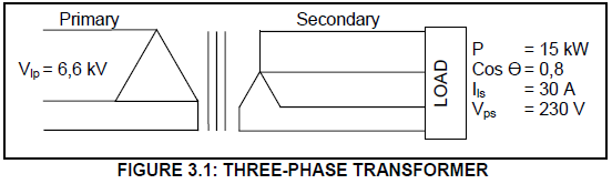
Given:
Vlp=6,6 kV
Vps=230 V
Ils=30 A
Pout=15 kW
Cos Ɵ=0,8
Calculate the:
3.6.1 Primary phase voltage (2)
3.6.2 Secondary phase current (2)
3.6.3 Primary phase current (3)
3.6.4 Turns ratio (3)
[20]
QUESTION 4: THREE-PHASE MOTORS AND STARTERS
4.1 Name ONE application of a three-phase motor. (1)
4.2 State THREE advantages of a three-phase motor compared to a single-phase motor. (3)
4.3 A star-delta starter is used to reduce the starting current used by a motor when starting.
4.3.1 Describe why it is necessary to do this. (3)
4.3.2 Describe how the starter reduces the starting current. (3)
4.4 Describe the principle of operation of a three-phase squirrel-cage induction motor. (7)
4.5 FIGURE 4.1 represents the terminals of a three-phase induction motor. Answer the questions that follow.
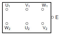
FIGURE 4.1: TERMINALS OF A THREE-PHASE INDUCTION MOTOR
4.5.1 Redraw the terminal box in FIGURE 4.1. Then draw in the motor coils and show them connected in star. (5)
4.5.2 A megger set on the insulation resistance setting is connected across W1 and U2. Describe what type of reading should be expected if the motor is in good working order. (3)
4.5.3 A megger set on the insulation resistance setting is connected across U1 and E. If the reading on the meter shows a low resistance, describe why the motor should not be energised. (3)
4.6 Calculate the number of pole pairs of a three-phase motor if the motor is connected to a 50 Hz supply and has a synchronous speed of 600 r/min.
Given:
f=50 Hz
ns=600(3)
4.7 A three-phase delta-connected motor is connected to a 380 V/50 Hz supply. The motor draws a current of 16 A at full load. It has a power factor of 0,85 and an efficiency of 90%.
Given:
Il=16 A
Vl=380 V
Pf=0,85
ɳ=90%
Calculate the:
4.7.1 Input kVA (3)
4.7.2 Power developed by the motor at 100% efficiency (3)
4.7.3 The actual output power of the motor (3)
[40]
QUESTION 5: RLC
5.1 Name the TWO factors that influence the reactance of a capacitor. (2)
5.2 Distinguish between the two concepts reactance and impedance. (2)
5.3 Draw the typical frequency/impedance characteristic curve of a series RLC circuit. The graph must show the relationship between impedance and frequency, as the frequency changes. The graph must also show the resonant point of the circuit. (4)
5.4 Calculate the Q-factor of a series RLC circuit that resonates at 6 kHz. The coil and the capacitor each have a reactance of 4 kΩ at resonance. The coil and the capacitor are connected in series with a 50 Ω resistor.
Given:
fr=6 kHz
Xl=4 kΩ
Xc=4 kΩ
R=50 Ω(3)
5.5 Refer to the circuit diagram in FIGURE 5.1.
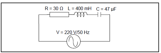
FIGURE 5.1: SERIES RLC CIRCUIT
Given:
R=30 Ω
L=400 mH
C=47 μF
f=50 Hz
Calculate the:
5.5.1 Inductive reactance of the coil (3)
5.5.2 Capacitive reactance of the capacitor (3)
5.5.3 Frequency at which the circuit will resonate (3)
[20]
QUESTION 6: LOGIC
6.1 State TWO advantages of a programmable logic controller (PLC) compared to a hard-wired system. (2)
6.2 Draw a block diagram of a PLC scan cycle showing the THREE steps that are used to execute a programme. Label each step and indicate its function. (6)
6.3 Name TWO output devices that may be connected to a PLC. (2)
6.4 Simplify the equation below using Boolean algebra:![]()
6.5 Name THREE programming methods used to instruct a PLC. (3)
6.6 Consider the following Boolean equation and answer the questions that follow:![]()
6.6.1 Convert the equation into a Karnaugh map. (Remember to group.) (6)
6.6.2 Derive and write the simplified Boolean equation from the Karnaugh map in your ANSWER BOOK. (3)
6.7 Refer to the circuit diagram in FIGURE 6.1 and answer the questions that follow.
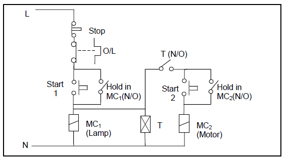
FIGURE 6.1: RELAY CONTROL CIRCUIT
6.7.1 Identify the circuit in FIGURE 6.1. (2)
6.7.2 Draw the PLC ladder logic diagram that would execute the relay control circuit in FIGURE 6.1. Your diagram must include a marker or a flag function. (8)
6.7.3 Explain why the marker or flag is used in the drawing of the ladder diagram in QUESTION 6.7.2. (3)
[40]
QUESTION 7: AMPLIFIERS
7.1 Name TWO characteristics of an ideal op amp. (2)
7.2 Describe the term bandwidth. (3)
7.3 Describe the term positive feedback. (3)
7.4 Draw and label the circuit symbol of an op amp. Include the power terminals. (6)
7.5 With reference to the ideal op-amp circuits below, draw the given input and output wave-form diagrams on the same y-axis. Label the wave forms.
7.5.1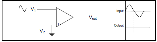
FIGURE 7.1: IDEAL OP-AMP CIRCUIT (3)
7.5.2 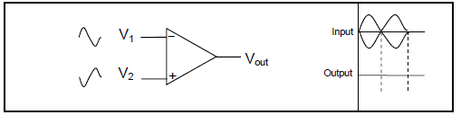
FIGURE 7.2: IDEAL OP-AMP CIRCUIT (3)
7.6State TWO advantages of using negative feedback in an op-amp circuit. (2)
7.7 Refer to FIGURE 7.3 and answer the questions that follow.
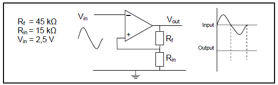
FIGURE 7.3: OP-AMP CIRCUIT
7.7.1 Identify the op-amp configuration. (1)
7.7.2 Draw the input and output signal on the same y-axis. Label the wave forms. (3)
7.7.3 Calculate the voltage gain. (3)
7.7.4 Calculate the output voltage if an input signal of 2,5 V is applied to the op amp. (3)
7.8 Name TWO applications of an astable multivibrator circuit. (2)
7.9 With reference to FIGURE 7.4, draw the input wave form shown in FIGURE 7.5 and the output wave form directly below it.
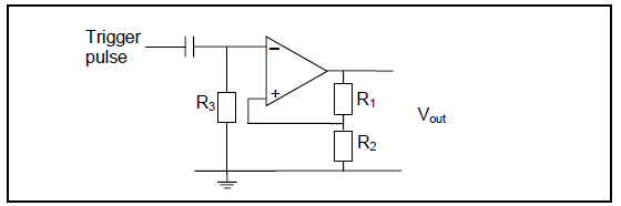
FIGURE 7.4: BI-STABLE MULTIVIBRATOR
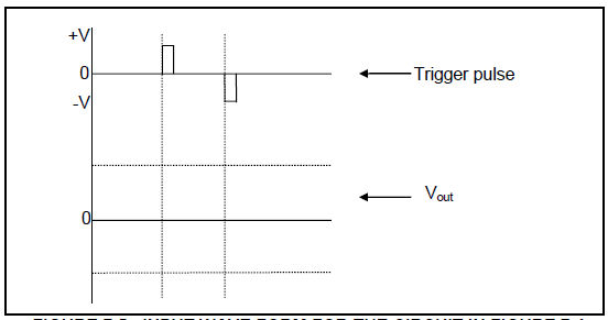
FIGURE 7.5: INPUT WAVE FORM FOR THE CIRCUIT IN FIGURE 7.4 (4)
7.10 With reference to FIGURE 7.6, answer the questions that follow.
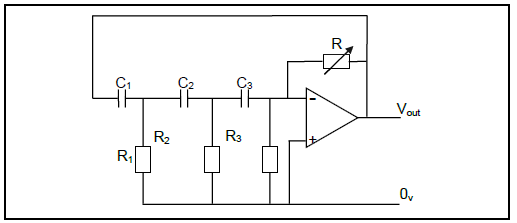
FIGURE 7.6: RC PHASE-SHIFT OSCILLATOR
7.10.1 Identify the type of feedback used in the RC phase-shift oscillator. (1)
7.10.2 State ONE application of the oscillator. (1)
7.10.3 Calculate the oscillation frequency for an RC phase-shift oscillator that uses three RC networks. The resistors are all 15 Ω. The capacitors are all 150 nF. (3)
7.11 With reference to FIGURE 7.7, answer the questions that follow.
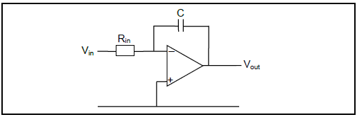
FIGURE 7.7: OP-AMP INTEGRATOR CIRCUIT
7.11.1 State ONE application of the integrator circuit. (1)
7.11.2 Draw the input and output wave forms of the op-amp integrator circuit. (6)
[50]
TOTAL: 200
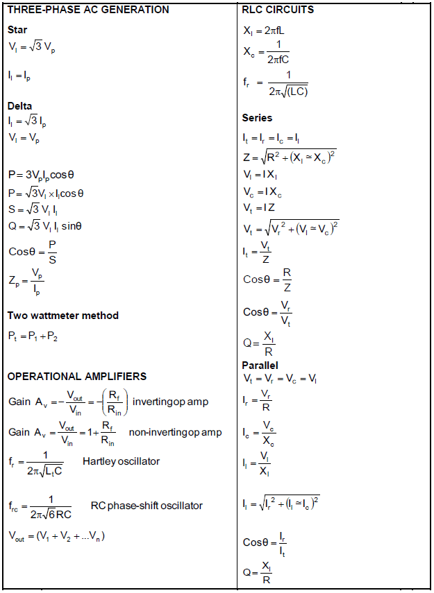
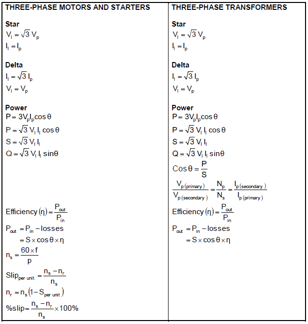
FORMULA SHEET