ENGINEERING GRAPHICS AND DESIGN PAPER 2 GRADE 12 QUESTIONS - NSC PAST PAPERS AND MEMOS FEBRUARY/MARCH 2016
Share via Whatsapp Join our WhatsApp Group Join our Telegram GroupNATIONALSENIOR CERTIFICATE
GRADE 12
ENGINEERING GRAPHICS AND DESIGN P2
FEBRUARY/MARCH 2016
INSTRUCTIONS AND INFORMATION
- This question paper consists of FOUR questions
- Answer ALL the questions
- All drawing are in third-angle orthographic design projection, unless otherwise stated
- ALL drawings must be completed using instruments, unless otherwse stated
- ALL answers must be drawn neatly
- ALL the questions must be answered on the QUESTION PAPER as instructed
- ALL the pages, irrespective of whether the question was attempted or not, must be re-stapled in numerical sequence in the TOP LEFT-HAND CORNER ONLY
- Proper planning is essential in order to complete all the questions
- Print your examination number in the block provided on every page
- Any details or dimensions not given must be assumed in good proportion
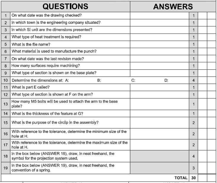
QUESTION 1: ANALYTICAL (MECHANICAL)
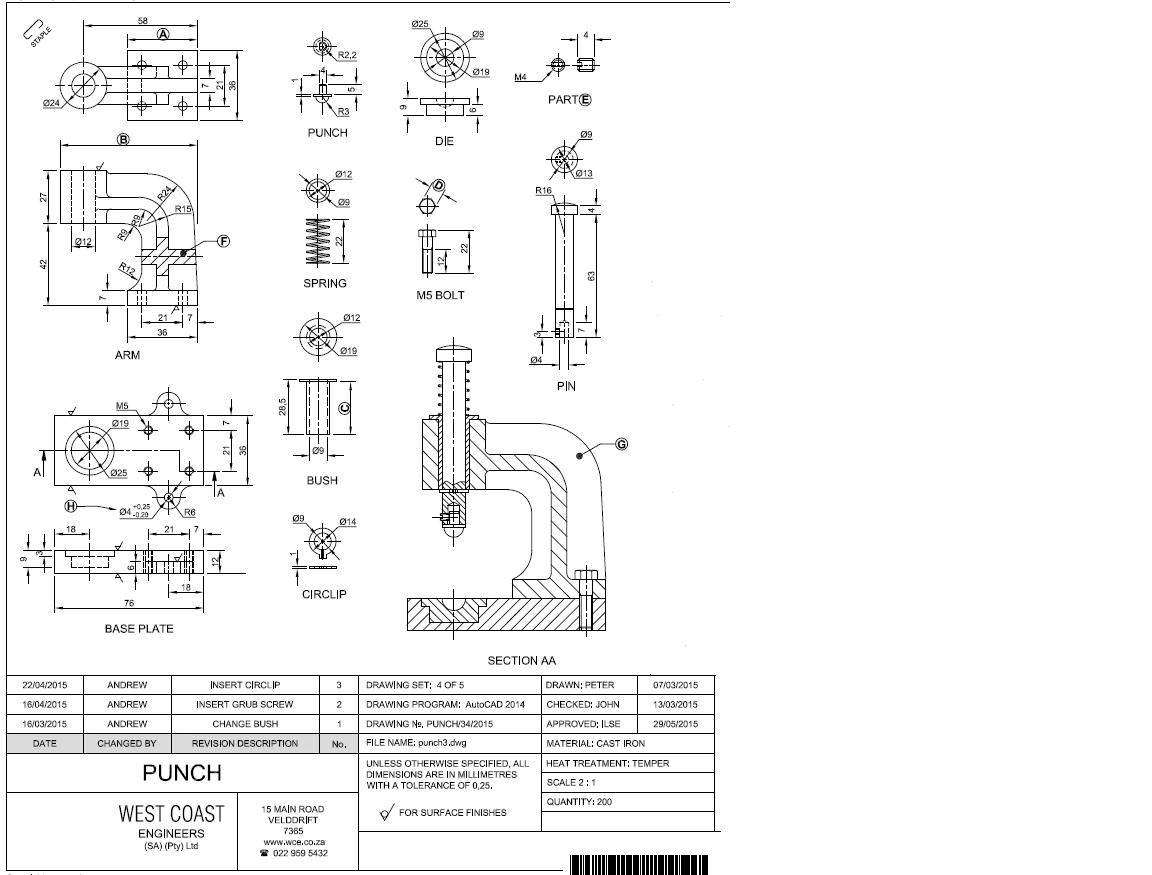
Given:
Drawings of the parts of a punch, a sectional view of the punch assembly, a title block and a table of questions. The drawings have not been prepared according to the indicated scale
Instructions:
Complete the table below by neatly answering the questions, which all refer to the accompanying detailed drawings and the title block.
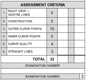
ANSWER 18
| ANSWER 19 |
QUESTION 2: LOCI (HELIX)
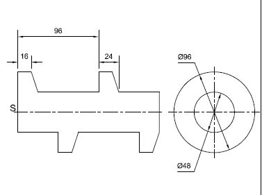
Given:
- The core and the profile of the incomplete front view as well as the right view of a shaft with a unique single-start right-handed thread
- The position of S on the drawing sheet
Specifications:
- Pitch = 96
- Turns = ONE and a HALF
- Direction = Right-handed
Instructions:
Draw, to scale 1:1, the following views of the shaft with a unique single-start right-handed thread;
2.1 The given right view
2.2 The complete front view
- Show ALL necessary construction
- NO hidden detail is required [32]
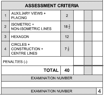
QUESTION 3: ISOMETRIC DRAWING
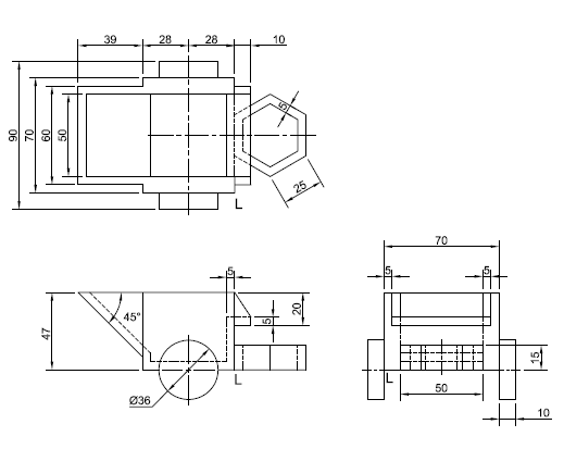
Given:
- The front view, top view and right viewo f a toy planter
- The position of corner L on the drawing sheet
Instructions:
Using scale 1:1, convert the orthographic views of the toy planter into an isometric drawing.
- Use corner L as the starting point of the drawing
- Show ALL necessary construction
- NO hidden detail is required. [40]
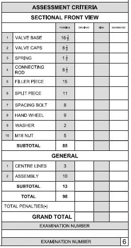
QUESTION 4: MECHANICAL ASSEMBLY
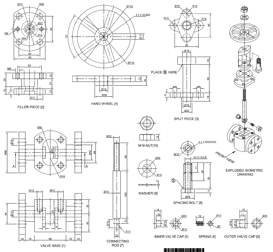
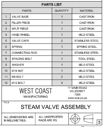
Given:
- The exploded isometric drawing of the parts of a steam valve assembly, showing the position of each part relative to all the others
- Orthographic views of each of the parts of the steam valve assembly
Instructions:
- Answer this question on page 6
- Dra, to scale 1:1 and in third-angle orthographic projection, a sectional front-view on cutting plane A-A , as seen from the direction of the arrow shown on the exploded isometric drawing. The cutting plane, which passes vertically through the centre of the assembly, is shown on the top view of the valve base (part1).
- ALL drawings must comply with the guidelined as contained in the SANS 1011
NOTE:
- Planning is essential
- The M12 bolts (part 12) which connect the filler piece (part 2) to the valve base (part 1) are not shown and not required to be drawn
- The M8 bolts (part 11) which connect the filler piece (part 2) to the split piece (part 3) are not shown and not required to be drawn
- The spacing bolt (part 8) must be places through the split piece (part 3) so that point S will be at the indicated position.
- Show THREE faces of the M18 nut
- NO hidden detail is required. [98]