MECHANICAL TECHNOLOGY GRADE 12 MEMORANDUM - NSC PAST PAPERS AND MEMOS FEBRUARY/MARCH 2017
Share via Whatsapp Join our WhatsApp Group Join our Telegram GroupMECHANICAL TECHNOLOGY
GRADE 12
NSC PAST PAPERS AND MEMOS
FEBRUARY/MARCH 2017
MEMORANDUM
QUESTION 1: MULTIPLE-CHOICE QUESTIONS
1.1 B ✔ (1)
1.2 D ✔ (1)
1.3 C ✔ (1)
1.4 C ✔ (1)
1.5 B ✔ (1)
1.6 D ✔ (1)
1.7 A ✔ (1)
1.8 B ✔ (1)
1.9 A ✔ (1)
1.10 B ✔ (1)
1.11 B ✔ (1)
1.12 B ✔ (1)
1.13 D ✔ (1)
1.14 D ✔ (1)
1.15 A ✔ (1)
1.16 C ✔ (1)
1.17 A ✔ (1)
1.18 B ✔ (1)
1.19 B ✔ (1)
1.20 A ✔ (1)
[20]
QUESTION 2: SAFETY
2.1 Safety – Coil spring compressor:
- Make certain that the diameter of the compressor bolts can take the pressure of the coil spring. ✔
- Do not exceed the maximum pressure. ✔
- Make sure the compressors are clean and free from oil. ✔
- Ensure that the compressors are in a good working condition. ✔
(Any 2 x 1) (2)
2.2 Safety – Hydraulic Press:
- Take notice of the predetermined pressure of the hydraulic press. ✔
- Ensure the pressure gauge is in a good working order. ✔
- Platform on which the work piece rests must be rigid and square with the cylinder of the press. ✔
- The prescribed equipment must be used. ✔
- Check for oil leaks. ✔
(Any 3 x 1) (3)
2.3 Safety – beam bender:
- Ensure the beam is clamped parallel to the backboard. ✔
- Do not leave plastic beams loaded for any length of time, they tend to creep. ✔
- All the weight must be gently dropped onto the hanger as to reduce inaccuracies due to friction. ✔
- Do not exceed the tester's maximum load. ✔
- Make sure the tester is stable. ✔
(Any 2 x 1) (2)
2.4 Testers:
2.4.1 Brinell Tester:
- The tester must be mounted rigidly on a worktable. ✔ (1)
2.4.2 Bearing and gear Puller:
- Make sure that the puller is at 90° to the work piece before you start to pull. ✔
- ∙ Ensure that the clamps are tight and will not slip from the work piece. ✔
(Any 1 x 1) (1)
2.4.3 Torsion tester:
- Get specification (torsion) of the different materials and the size of rods you would like to test. ✔ (1)
[10]
QUESTION 3: TOOLS AND EQUIPMENT
3.1 Fuel pressure:
- Faulty diaphragm ✔
- Clogged fuel filter ✔
- Faulty non return valves ✔
- Worn gasket ✔
(Any 2 x 1) (2)
3.2 Precision measuring instruments:
3.2.1 Depth micro-meter ✔
- Vernier calliper ✔
(Any 1 x 1) (1)
3.2.2 Screw-thread micro-meter ✔ (1)
3.3 Depth micro-meter reading:
- Reading = 50 + 1,5+ 0,49 ✔
= 51,99 mm. ✔ (2)
3.4 Multimeter measurements:
- DC current measurement ✔
- DC voltage measurement ✔
- AC measurement ✔
- Resistance measurement ✔
- Diode measurement ✔
- Continuity measurement ✔
(Any 2 x 1) (2)
3.5 Trace the cylinder leakage in an engine:
- Listen to at the carburettor for a hissing noise. ✔
- Listen at the exhaust pipe for a hissing noise. ✔
- Listen for hissing noise in the dipstick hole. ✔
- Listen to hissing noise by removing the filler cap on the tappet cover. ✔
- By checking whether there are bubbles in the radiator water for blown cylinder head gasket or cracked cylinder block. ✔
(Any 2 x 1) (2)
3.6 Uses of cooling pressure tester:
- To test if the pressure cap on the cooling system operates according to the prescribed pressure of the system. ✔
- To pump compressed air into the cooling system to determine whether they are any water leakage in the system. ✔ (2)
[12]
QUESTION 4: MATERIALS
4.1 Properties/characteristics:
4.1.1 Cementite:
- Hard and brittle ✔✔ (2)
4.1.2 Pearlite:
- Good ductility ✔
- Very hard ✔
- Strong and tough ✔
- Resistance to deformation ✔
(Any 2 x 1) (2)
4.2 Iron –carbon equilibrium diagram
4.2.1 Iron –carbon equilibrium diagram ✔ (1)
4.2.2
- – Ferrite + Pearlite ✔
- – Austenite + Ferrite ✔
- – Austenite ✔
- – Austenite + Cementite ✔
- – Ferrite + Cementite ✔ (5)
4.2.3 Austenite:
- Soft, ✔ grain structure fine ✔ (2)
4.3 720 °C ✔ (1)
[13]
QUESTION 5: TERMINOLOGY
5.1 Indexing:
- Indexing = 40 ✔
n
= 40 ÷ 2 ✔
118 2
= 20 ✔ (3)
59
No fullturnsand 20 holes in a 59 -hole plate
5.2 Milling processes:
- Up-cut milling (2)

- Downcut milling (2)

5.3 Calculate: Gib head key:
5.3.1
- Width = D
4
= 102 ✔
4
= 25,5 mm (2) ✔
5.3.2
- Thickness = D
6
= 102 ✔
6
= 17 mm (2) ✔
5.3.3
- Length = D × 1.5
= 102 × 1.5 ✔
= 153 mm (2) ✔
5.3.4
- Thickness at smallend(t ) T = − L
100
= 17 - 153 ✔
100
t = 17 - 1,53
= 15,47 mm (4) ✔
5.4 Calculate – Spur gear:
5.4.1
- Addendum = m
= 3 mm ✔ (1)
5.4.2
- Dedendum = 1,157m or = 1,25m
= 1,157 x 3 ✔ = 1,25 x 3 ✔
= 3,47 mm ✔ = 3,75 mm ✔ (2)
5.4.3
- Clearance = 0,157m or = 0,25m
= 0,157 x 3 ✔ = 0,25 x 3 ✔
= 0,47 mm ✔ = 0,75 mm ✔ (2)
5.4.4
- Module = PCD
T
PCD = m × T ✔
= 3 × 60
= 180mm ✔(2)
5.4.5
- OD = PCD + 2m
= 180 + 2(3)
= 180 + 6 ✔
= 186 mm ✔ (2)
5.4.6
- Cutting depth = 2,157 m or = 2,25 m
= 2,157 x 3 ✔ = 2,25 x 3 ✔
= 6,47 mm ✔ = 6,75 mm ✔ (2)
5.4.7
- Circular pitch = m x π
= 3 x π ✔
= 9,43 mm ✔ (2)
[30]
QUESTION 6: JOINING METHODS
6.1 Slag inclusion ✔ (1)
6.2 Visual inspection defects
- Shape of profile ✔
- Uniformity of surface ✔
- Overlap ✔
- Undercutting ✔
- Penetration bead ✔
- Root groove ✔
- Crack free ✔
(Any 4 x 1) (4)
6.3 Causes of incomplete penetration:
- Weld speed too fast ✔
- Joint design faulty ✔
- Electrode too large ✔
- Current too low ✔
(Any 2 x 1) (2)
6.4 Prevention of lack of fusion
- Adjust electrode size ✔
- Correct preparation of joint ✔
- Correct weld current ✔
- Correct arc length ✔
- Correct weld speed ✔
(Any 2 x 1) (2)
6.5 Destructive test
6.5.1 Machinability test ✔ (1)
6.5.2 Nick-break test ✔ (1)
6.5.3 Bend test ✔ (1)
6.6 Dye penetration test
- Clean the weld that needs to be tested. ✔
- Spray dye onto the surface and leave to penetrate. ✔✔
- Excess dye is cleaned away with a cleaning agent. ✔
- Allow surface to dry. ✔
- Spray a developer onto the surface to bring out the dye trapped in the crack. ✔
- The dye will show all the surface defects. ✔ (7)
6.7 Functions of MIG/MAGS components
6.7.1 Wire feed controller
- Feeds the consumable electrode wire to the welding gun at a constant predetermined speed. ✔✔ (2)
6.7.2 Welding gun
- Activates the supply of gas, power and wire feed✔✔ (2)
6.8 Purpose of inert gas
- The inert gas shields the molten pool from the atmospheric gases. ✔✔ (2)
[25]
QUESTION 7: FORCES
7.1 Forces 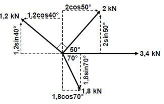
∑HC = 3,4 (√) + 1,8cos70º (√) - 1,2cos40º (√) + 2cos50º (√)
= 3,4 + 0,62 - 0,92 + 1,29
= 4,39 kN (√)
∑VC = 1,2 sin40 (√) + 2sin50º (√) - 1,8sin70º (√)
= 0,77 + 1,53 - 1,69
= 0,61 kN (√)
OR
Horizontal component | Magnitudes | Vertical component | Magnitudes |
-1,2cos40°✔ | -0,92 kN | 1,2sin40✔ | 0,77 |
3,4 ✔ | 3,4kN | 0 | 0 |
2cos50°✔ | 1,29kN | 2sin50°✔ | 1,53 |
1,8cos70°✔ | 0,62kN | -1,8sin70°✔ | 1,69 |
TOTAL | 4,39kN ✔ | TOTAL | 0,61kN ✔ |
- R2 = HC2 + VC2
R = √4,392 + 0.612
R = 4,43 kN - Tanθ = VC
HC
= 0,61
4,39
θ = 7,91º
R = 4,43 N at 7,91º northe of east (13)
7.2 Stress and Strain
7.2.1 Stress:
- A = π(D2 - d2)
4
A = π(0,0982 - 0,0672)
4
= 4,02 × 10⁻³ m2
σ = F
A
σ = 40000
4,02 × 10⁻³
σ = 9950248,76Pa
σ = 9,95 MPa (5)
7.2.2 Strain:
- ε = σ
E
ε = 9,95 × 10⁶
90 × 109
= 0,11 × 10⁻³ or 1,11 × 10⁻⁴ (3)
7.2.3 Change in length
- ε = ΔI
oI
ΔI = ε × ol
= (0,11 × 10-3) × 0,08
=8,8 × 10⁻⁶m
= 8,8 × 10⁻³ mm (3)
7.3 Moments
Calculate A. Moments about B
- ∑RHM =∑ LHM
(A × 11,6) = (200 × 5,8) + (928 × 5,8) + (600 × 2,8)
11,6A = 1160 + 5382,4 + 1680
11,6A = 8222,4
11,6 11,6
A = 708,83 N
Calculate B. Moments about A
- ∑LHM =∑ RHM
(B × 11,6) = (600 × 8,8) + (928 × 5,8) + (200 × 5,8)
11,6B = 5280 + 5382,4 + 1160
11,6B = 11822,40
11,6 11,6
B = 1019,17 N (6)
[30]
QUESTION 8: MAINTENANCE
8.1 Preventative maintenance
- Can be described as maintenance of equipment or system before a fault occurs.✔ ✔ (2)
8.2 Lock out
- Locking out means that the machine's start switch cannot be activated without the knowledge of a servicing technician otherwise an accident would occur.✔ ✔ (2)
8.3 Clutch free-play
- The distance the pedal moves before the slack is taken from the linkage and release bearing. ✔ ✔ (2)
8.4 Viscosity index
- Viscosity index is a measure of how much the oil's viscosity changes as temperature changes. ✔ (1)
8.5 Replace clutch plate:
- Worn friction linings. ✔
- Weak or broken springs. ✔
- Glazed friction linings due to overheating. ✔
- Oil on friction linings. ✔
(Any 2 x 1) (2)
8.6 Grease – high viscosity
- To ensure that the grease coats and sticks ✔ to the bearing surfaces it is lubricating. ✔ (2)
8.7 Cutting fluid
- Mixture of soluble oil ✔ and water. ✔ (2)
8.8 Viscosity of cutting fluid
- Has a low viscosity to allow easy flow ✔ and effective dissipation of excess heat. ✔ (2)
[15]
QUESTION 9: SYSTEMS AND CONTROL
9.1 Gear drives
9.1.1 Rotation frequency of the output shaft
- NINPUT = TB × TD
NOUTPUT TA × TC
NOUTPUT = TA × TC × NINPUT
TB × TD
NIOTPUT = 18 × 16 × 1660
36 × 46
= 288,70 r/min (3)
9.2.2 Velocity Ratio
- VR = NINPUT
NOUTPUT
= 1660
288,70
= 5,75: 1 (2)
9.2 Belt Drives
9.2.1 Rotation frequency of the driver pulley π(D t) N
- V = π( D + t) × N
60
N = V × 60
π(D + t)
N = 36 × 60
π(230 + 12) × 10-3
2841,11r/min (4)
9.2.2 Power transmitted
- T1 = 2,5
T2
T1 = 2,5 × T2
=2,5 × 110
= 275 N - P = (T1 - T2)V
P = (275 - 110) × 36
= 5940W
5,94kW (4)
9.3 Hydraulics
9.3.1 Fluid pressure
- AB = πD2
4
= π × 0.0752
4
= 4.42 × 10⁻³ m2 - PB = F
AB
= 700 × 10 Pa
4.42 × 10-3
= 1583710, 41Pa
= 1583, 71 kPa ✔ (4)
9.3.2 Effort on piston A
- AA = πD2
= π × 0.042
4
= 1,256 × 10-3 m2 - PA = FA
AA
FA = PA × AA
=(1583,71 × 103) × (1,256 × 10-3)
= 1990,10 N
= 1,99 kN (4)
9.4 ABS
- Prevents wheel from locking during heavy breaking. ✔✔ (2)
9.5 Seat belt
- A seat belt has to be activated for its safety to be functional. ✔✔ (2)
[25]
QUESTION 10: TURBINES
10.1 Impulse Turbine
- Waterwheel ✔
- Pelton ✔
- Turgo ✔
- Michell – Banki/Crossflow/Ossberger✔
- Jonval turbine ✔
- Reverse overshot waterwheel ✔
- Archimedes' screw turbine ✔
(Any 2 x 1) (2)
10.2 Water turbine
10.2.1
- Water turbine ✔
- Kaplan-turbine ✔
- Reaction turbine ✔
(Any 1 x 1) (1)
10.2.2 Parts
- – Wicked gate ✔
- – Rotor ✔
- – Stator ✔
- – Shaft ✔
- – Water-flow ✔
- – Blades ✔ (6)
10.2.3 Advantages of water turbine
- Low maintenance ✔
- No need for lubrication ✔
- Fewer moving parts ✔
- Environmental friendly ✔
- Cost effective ✔
(Any 2 x 1) (2)
10.3 Turbines
10.3.1 Advantage of supercharger:
- Increases the output power of the engine. ✔
- A smaller engine fitted with a centrifugal blower delivers the same power as a larger engine. ✔
- It eliminates lack of oxygen above sea level. ✔
- Increases the volumetric efficiency of the engine. ✔
- With the aid of the intercooler both the power and the torque output of the engine are increased. ✔
(Any 2 x 1) (2)
10.3.2 Advantages of steam turbines:
- It is compact. ✔
- No lubrication is required. ✔
- Steam turbine speeds can be more accurately regulated. ✔
- A variety of fuels can be used to obtain steam. ✔
- Steam turbines are more economical. ✔
- Higher speeds can be obtained as compared to internal combustion engine. ✔
- Convert heat energy into mechanical energy. ✔
(Any 2 x 1) (2)
10.3.3 Advantages of gas turbines:
- Very high power to weight ratio ✔
- Smaller than most reciprocating engines of the same power rate ✔
- Moves in one direction only, with far less vibration ✔
- Low operating pressures ✔
- High operating speeds ✔
- Low lubricating oil cost and consumption ✔
(Any 2 x 1) (2)
10.4 Turbo lag
- It is a delay ✔ between pushing on the accelerator ✔ and feeling turbo kick in. ✔ (3)
[20]
TOTAL: 200