ELECTRICAL TECHNOLOGY GRADE 12 QUESTIONS - NSC PAST PAPERS AND MEMOS FEBRUARY/MARCH 2017
Share via Whatsapp Join our WhatsApp Group Join our Telegram GroupELECTRICAL TECHNOLOGY
GRADE 12
NSC PAST PAPERS AND MEMOS
FEBRUARY/MARCH 2017
INSTRUCTIONS AND INFORMATION
- This question paper consists of SEVEN questions.
- Answer ALL the questions.
- Sketches and diagrams must be large, neat and fully labelled.
- Show ALL calculations and round off answers correctly to TWO decimal places.
- Number the answers correctly according to the numbering system used in this question paper.
- You may use a non-programmable calculator.
- Show the units for all answers of calculations.
- A formula sheet is provided at the end of this question paper.
- Write neatly and legibly.
QUESTIONS
QUESTION 1: OCCUPATIONAL HEALTH AND SAFETY
1.1 State TWO unsafe acts that may lead to an accident. (2)
1.2 Distinguish between an unsafe act and an unsafe condition. (2)
1.3 State FOUR points in the procedure that should be followed when a person is experiencing an electric shock. (4)
1.4 Explain why a person under the influence of alcohol may not operate machinery in the workplace. (2)
[10]
QUESTION 2: THREE-PHASE AC GENERATION
2.1 Define the following terms:
2.1.1 Active power (2)
2.1.2 Reactive power (2)
2.2 Draw a neat, labelled diagram that represents the waveforms of a three phase AC-generated system. (5)
2.3 A balanced three-phase inductive load is connected in delta across a three phase supply. The load draws a current of 30 A from the 380 V/50 Hz supply. It has a power factor of 0,75 lagging.
Given:
IL = 30 A
VL = 380 V
p.f. = 0,75 lagging
Calculate the:
2.3.1 Phase current (3)
2.3.2 Impedance of the load (3)
2.3.3 State what will happen to the current drawn by the load if the power factor of the load is improved. (1)
2.3.4 State ONE economic benefit of improving the power factor. (1)
2.4 The two-wattmeter method is used to measure the power drawn by an induction motor. The readings on the wattmeters are 100 W and 250 W respectively. Calculate the total input power.
Given:
P1 = 100 W
P2 = 250 W (3)
[20]
QUESTION 3: THREE-PHASE TRANSFORMERS
3.1 State the purpose of a transformer. (1)
3.2 Name TWO cooling methods used in a transformer. (2)
3.3 State where a delta-star transformer connection is used. (1)
3.4 FIGURE 3.1 below represents the delta-star connection of a three-phase transformer.
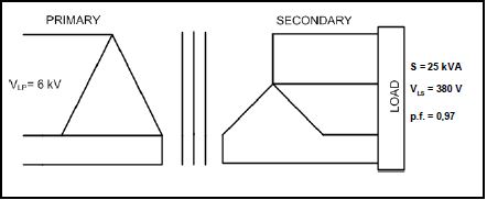 |
| FIGURE 3.1: THREE-PHASE TRANSFORMER |
Given:
S = 25 kVA
VLP = 6 kV
VLS = 380 V
p.f. = 0,97 lagging
Calculate the:
3.4.1 Secondary line current (3)
3.4.2 Primary line current (3)
3.4.3 Primary phase current (3)
3.4.4 Transformation ratio (3)
3.5 Explain why the secondary turn of a distribution transformer is connected in star. (2)
3.6 State why regular maintenance of transformers is important. (2)
[20]
QUESTION 4: THREE-PHASE MOTORS AND STARTERS
4.1 State ONE advantage of a three-phase induction motor over a single-phase induction motor. (1)
4.2 Describe why it is important that the rotor of a motor rotates freely before it is energised. (2)
4.3 State TWO electrical tests that must be done on a motor before it is energised. (2)
4.4 Describe ONE condition that may exist if there is an electrical connection between the rotor and the stator of a three-phase induction motor. (2)
4.5 State TWO losses that occur in a three-phase motor. (2)
4.6 A three-phase delta-connected motor, rated at 15 kVA, is connected to a 380 V/50 Hz supply. The motor has a power factor of 0,8 and an efficiency of 95%.
Given:
VL = 380 V
S = 15 kVA
f = 50 Hz
p.f. = 0,8
ŋ = 95%
Calculate the:
4.6.1 Output power of the motor at full load if the motor is 100% efficient (3)
4.6.2 Output power of the motor at full load at 95% efficiency (3)
4.6.3 The current drawn by the motor (3)
4.7 Answer the following questions with reference to a three-phase induction motor.
4.7.1 State what will happen to the output power of the motor if the efficiency of the motor has been improved. (1)
4.7.2 Describe what will happen to the reactive power of the motor if the power factor of the motor has been improved. Structure your answer with reference to voltage, current and power. (3)
4.8 FIGURE 4.1 below represents the control circuit of a star-delta starter.
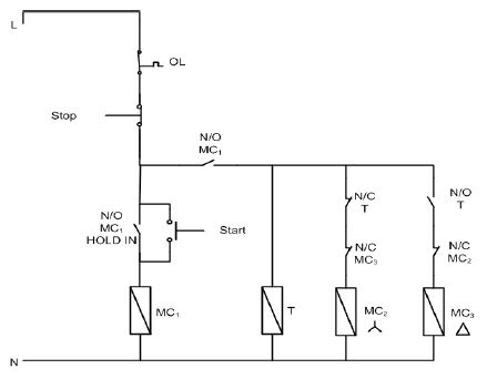 |
| FIGURE 4.1: CONTROL CIRCUIT OF A STAR-DELTA STARTER |
4.8.1 Describe how a star-delta starter reduces the starting current of the motor. (3)
4.8.2 State why it is necessary to reduce the starting current of a three phase induction motor. (3)
4.8.3 Describe the function of the overload unit in the starter. (3)
4.8.4 Describe the interlocking used in the circuit to prevent the motor from being switched into delta while still connected in star. (5)
4.9 Describe why induction motors must be supplied with a constant frequency. (3)
4.10 State how the number of pole pairs of an induction motor affects the speed of a motor. (1)
[40]
QUESTION 5: RLC
5.1 State TWO factors that influence the value of the reactance of a coil when connected across an AC supply. (2)
5.2 State how an increase in capacitance will affect the reactance of a capacitor. (1)
5.3 Explain the term resonance with reference to an RLC circuit. (3)
5.4 Refer to the diagram in FIGURE 5.1 below.
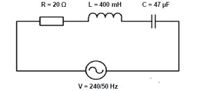 |
| FIGURE 5.1: RLC SERIES CIRCUIT |
Given:
R = 20 Ω
L = 400 mH
C = 47 µF
V = 240 V
f = 50 HZ
Calculate the:
5.4.1 Inductive reactance of the inductor (3)
5.4.2 Capacitive reactance of the capacitor (3)
5.4.3 Impedance of the circuit (3)
5.4.4 Q-factor of the circuit when the circuit is at resonance (3)
5.5 State, with a reason, whether the circuit in FIGURE 5.1 is more inductive or more capacitive. (2)
[20]
QUESTION 6: LOGIC
6.1 Answer the following questions in respect of PLCs.
6.1.1 Write the abbreviation PLC in full. (1)
6.1.2 State TWO advantages of a PLC system over relay logic. (2)
6.1.3 Name TWO input devices that may be connected to a PLC. (2)
6.1.4 Name ONE component that is still used to switch high-current devices on or off. (1)
6.1.5 Define the term program in relation to a PLC. (3)
6.1.6 Name ONE device used to control a PLC remotely. (1)
6.1.7 Draw a block diagram to illustrate the components of a PLC system. (5)
6.2 Simplify the following expression with Boolean algebra: ![]() (6)
(6)
6.3 Draw a three-variable Karnaugh map and simplify the following Boolean expression: ![]() (8)
(8)
6.4 Refer to the circuit in FIGURE 6.1 below.
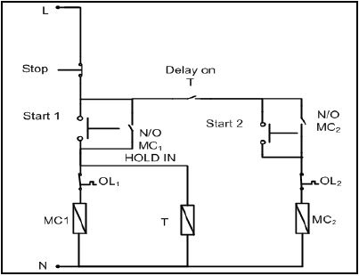 |
| FIGURE 6.1: SEQUENCE STARTER WITH A TIMER |
6.4.1 Draw the ladder logic diagram that would execute the same function in a PLC system. (10)
6.4.2 Name ONE electrical application of FIGURE 6.1. (1)
[40]
QUESTION 7: AMPLIFIERS
7.1 Draw and label the symbol of an operational amplifier (op amp). (5)
7.2 State THREE characteristics of an ideal op amp. (3)
7.3 Describe why op amp circuits are placed in an integrated circuit (IC) package. (2)
7.4 Describe what the term negative feedback means in respect of an op amp. (3)
7.5 State TWO advantages of negative feedback. (2)
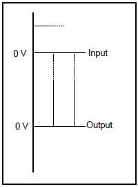
7.6 Refer to FIGURE 7.1 below and draw the output of an ideal op amp in relation to the input waveforms shown. (3)
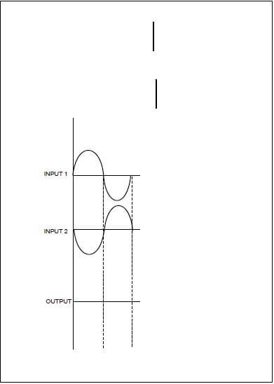 |
| FIGURE 7.1: OP AMP |
7.7 Refer to FIGURE 7.2 below and answer the questions that follow. +Vcc
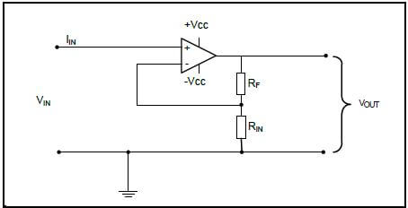 |
| FIGURE 7.2: NON-INVERTING OP AMP CIRCUIT |
7.7.1 Draw the input and output waveforms on the same Y-axis, as shown in FIGURE 7.3 below. (3)
 |
| FIGURE 7.3: OUTPUT WAVEFORM |
7.7.2 Calculate the voltage gain if the feedback resistance is 12 kΩ and the input resistor has a value of 3,3 kΩ.
Given:
RF = 12 kΩ
RIN = 3,3 kΩ
VIN = 6 V (3)
7.7.3 Calculate the output voltage if an input signal of 6 V is applied to the op amp. (3)
7.7.4 Describe what happens to the gain of the op amp if the value of RF is decreased. (2)
7.8 Refer to FIGURE 7.4 below and answer the questions that follow.FIGURE
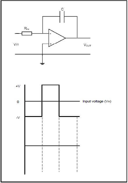 |
| 7.4: INTEGRATOR OP AMP CIRCUIT |
7.8.1 Draw and label the given input waveform and, in line directly below it, draw the output waveform. (6)
7.8.2 Describe the function of the capacitor in this op amp circuit. (3)
7.9 Refer to FIGURE 7.5 below and answer the questions that follow.
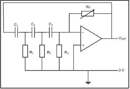 |
| FIGURE 7.5: RC PHASE-SHIFT OSCILLATOR CIRCUIT |
Given:
R1 = R2 = R3 = 12 kΩ
C1 = C2 = C3 = 260 nF
7.9.1 State TWO applications of the oscillator. (2)
7.9.2 Calculate the oscillating frequency of the oscillator. (3)
7.9.3 Identify the output waveform of the oscillator. (1)
7.9.4 State the type of feedback used in this oscillator. (1)
7.10 Describe the function of the dual DC supply to an op amp. (3)
7.11 Name the output waveform of a differentiator circuit when a triangular input wave is applied. (1)
7.12 State ONE application of a differentiator. (1)
[50]
TOTAL: 200
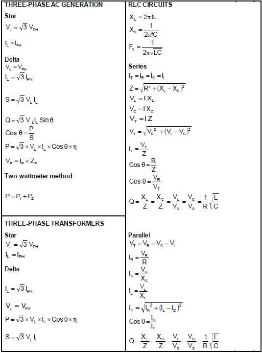
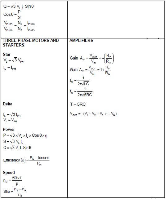
FORMULA SHEET