MECHANICAL TECHNOLOGY GRADE 12 - EXAMINATION GUIDELINES 2021
Share via Whatsapp Join our WhatsApp Group Join our Telegram GroupMECHANICAL TECHNOLOGY
EXAMINATION GUIDELINES
GRADE 12
2021
| TABLE OF CONTENTS | Page |
| 1. INTRODUCTION | 3 |
| 2. COGNITIVE LEVELS | 4 |
| 3. ELABORATION OF CONTENT FOR GRADE 12 (CAPS) | 5 |
| 4. STRUCTURE OF THE QUESTION PAPER 4.1 Fitting and Machining – Structure of question paper 4.2 Automotive – Structure of question paper 4.3 Welding and Metalwork – Structure of question paper | 6 7 13 16 |
| 5. CONCLUSION | 19 |
1. INTRODUCTION
The Curriculum and Assessment Policy Statement (CAPS) for Mechanical Technology outlines the nature and purpose of the subject Mechanical Technology. This guides the philosophy underlying the teaching and assessment of the subject in Grade 12.
The purpose of these Examination Guidelines is to:
- Provide clarity on the depth and scope of the content to be assessed in the Grade 12 National Senior Certificate Examination in Mechanical Technology.
- Assist teachers to adequately prepare learners for the examinations.
This document deals with the final Grade 12 external examinations. It does not deal in any depth with the school-based assessment (SBA), performance assessment tasks (PATs) or final external practical examinations as these are clarified in a separate PAT document which is updated annually.
This guideline should be read in conjunction with:
- National Curriculum Statement (NCS) Curriculum and Assessment Policy Statement (CAPS): Mechanical Technology
- National Protocol of Assessment: An addendum to the policy document, the National Senior Certificate: A qualification at Level 4 on the National Qualifications Framework (NQF), regarding the National Protocol for Assessment (Grades R–12)
- National policy pertaining to the programme and promotion requirements of the National Curriculum Statement, Grades R–12
These guidelines should be used in conjunction with the content outline per term and Section 4 of the CAPS document for Grade 12 Mechanical Technology specialisation. The duration of the final examination paper will be 3 hours with a maximum mark of 200. Summative assessment (examinations) will cater for a range of cognitive levels and abilities of learners.
THIS IS A GUIDELINE DOCUMENT AND NOT A WORK SCHEDULE.
2. COGNITIVE LEVELS
Blooms Taxonomy consists of six levels as shown below.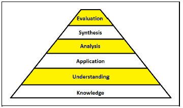
| Bloom's Taxonomy | Bloom's Revised Taxonomy | Description |
| Evaluation | Creating | Generating, planning, producing |
| Synthesis | Evaluating | Critiquing, judging, justifying, recommending |
| Analysis | Analysing | Differentiating, organising, attributing, solving |
| Application | Applying | Executing, implementing, preparing, using |
| Understanding | Understanding | Interpreting, exemplifying, classifying, summarising, inferring, comparing, explaining |
| Knowledge | Remembering | Recognising, recalling, labelling, naming |
The following cognitive levels and weighting thereof are applicable to the Mechanical Technology specialisations:
| Cognitive Levels | Weighting | |
| Lower order | Knowledge: memorise and recall information: arrange, define, label, list, outline, repeat, order | 30% |
| Comprehension: (understanding) interpret information in one's own words: describe, indicate, restate, review, summarise, classify | ||
| Medium order | Application: apply knowledge to new situations: apply, calculate, draw, explain, identify, illustrate, prepare, operate, practise, solve, sketch, use | 50% |
| Analysis: break down knowledge into parts and show relationship among parts: analyses, categorise, compare, distinguish, discuss, examine, investigate, test | ||
| Higher order | Synthesis: bring together parts of knowledge to form a whole; build relationships for new situation: arrange, compose, formulate, organise, plan, assemble, construct, problem-solving | 20% |
| Evaluation: make judgements on basis of criteria: appraise, assess, comment, critically analyse, evaluate, conclude, interrogate, judge, predict, compare, score | ||
3. ELABORATION OF CONTENT FOR GRADE 12 (CAPS)
BASIC SKILLS LINKED TO THE SUBJECT:
The following skills are measured in the question paper. The visibility of these skills gives an indication of the overall skills required in the subject:
- Ability to follow instructions
- Identifying labels/labelling/making drawings/diagrams/schematic representations
- Plotting and interpretation of graphs/data
- Working out and interpreting calculations
- Organising/Recording and categorising data
- Extraction and/or manipulation and/or evaluation of data
NOTE:
Calculations
Generally, the criteria used for calculations is as follows:
- Correct formula (Manipulation)
- Substitution of values
- Simplifying of values
- Answer and correct units
4. STRUCTURE OF THE QUESTION PAPER
This examination guidelines document is compiled with reference to the Mechanical Technology CAPS document that focuses on specialisation.
The INSTRUCTIONS AND INFORMATION part is the same for all three specialisations and this must be brought to the attention of the candidates.
The GENERIC questions for each of the specialisations are the same and have the same weighting.
The SPECIFIC questions focus only on content applicable for that specialisation.
Use the following FORMULA SHEET ANNEXURES for the specific specialisation:
4.1.1 ANNEXURE A (Fitting and Machining)
4.1.2 ANNEXURE B (Automotive)
4.1.3 ANNEXURE C (Welding and Metalwork)
4.1 FITTING AND MACHINING
| QUESTION | CONTENT | MARKS | TIME IN MINUTES |
| Generic | |||
| 1 | Multiple-choice questions | 6 | 6 |
| 2 | Safety | 10 | 10 |
| 3 | Materials | 14 | 14 |
| Specific | |||
| 4 | Multiple-choice Questions | 14 | 14 |
| 5 | Terminology (Lathe and Milling Machine) | 18 | 15 |
| 6 | Terminology (Indexing) | 28 | 24 |
| 7 | Tools and Equipment | 13 | 12 |
| 8 | Forces | 33 | 31 |
| 9 | Maintenance | 18 | 15 |
| 10 | Joining Methods | 18 | 15 |
| 11 | Systems and Control (Drive Systems) | 28 | 24 |
| TOTAL | 200 | 180 | |
ANNEXURE A (Fitting and Machining)
FORMULA SHEET FOR MECHANICAL TECHNOLOGY:
FITTING AND MACHINING
1 BELT DRIVES
1.1 Belt speed = πDN
60
1.2 Belt speed = π(D+t)xN
60
(t = belt thickness)
1.3 Belt mass = Area Length x Density
(A =thickness x width)
1.4 Speed ratio = Diameter of driven pulley
Diameter of driver pulley
1.5 Belt length (flat) – [(D+d)x1,57]+(2x centre distance)
1.6 Open belt length =π(D+d) + (D + d)2 + 2c
2 4c
1.7 Crossed belt length=π(D+d) + (D + d)2 + 2c
2 4c
1.8 Power (P) = (T1-T2 ) πDN
60
Where:
T1 = force in the tight side
T2 = force in the slack side
T1 -T2 -effective tensile force (Te)
1.9 Ratio between tight side and slack side = T1
T2
1.10 Power (P)= 2πNT
60
1.11 Width = T1
Permissable tensile force
1.12 NDR x DDR = NDN X DDN
2 STRESS AND STRAIN
2.1 Ashaft = πd2
4
2.2 Apipe= π(D2 - d2)
4
2.3 Safety factor = Maximum stress/Break stress
Safe working stress
2.4 Stress = Force OR σ - F
Area A
2.5 Strain = Change in length OR ε = ΔL
Original length L
2.6 Young's modulus = Stress OR E = σ
Strain ε
3. HYDRAULICS
3.1 Pressure = Force OR P = F
Area A
3.2 Volume = Area x Stroke length (l or s)
3.3 Work done = Force x Distance
3.4 PA =PB
3.5 FA = FB
AA AB
4 GEAR DRIVES
4.1 Power (P) = 2πNT
60
4.2 Gear ratio = Product of teeth on driver gear OR Speed ratio = NINPUT
Product of teeth on driven gear NOUTPUT
4.3 NINPUT = Product of the number of teeth on driven gears
NOUTPUT Product of the number of teeth on driver gears
4.4 NA x TA = NB x TB
4.5 Torque = Force x Radius
4.6 Torque transmitted = Gear ratio x Input torque
4.7 Module - Pitch circle diameter OR m = PCD
Number of teeth T
4.8 Pitch circle diameter = Circlular pitch x Number of teeth OR PCD = CP x T
π π
4.9 Outside diameter (OD)- PCD + 2(m)
4.10 Addendum = Module OR a = m
4.11 Dedendum (b)=1,157(m) OR Dedendum (b) = 1,25(m)
4.12 Cutting depth (h)= 2,157 (m) OR Cutting depth (n) = 2,25 (m)
4.13 Clearance (c)-0,157 (m) OR Clearance (c)= 0,25 (m)
4.14 Circular pitch (CP)=mxπ
4.15 Working depth (WD) = 2 xm
5 PULLEYS
5.1 NDR x DDR = NDN x DDN
5.2 Power (P) = 2πNT
60
5.3 Velocity ratio=Diameter of driven pulley
Diameter of driver pulley
6. KEYWAYS
6.1Width of key = Diameter of shaft
4
6.2 Thickness of key - Diameter of shaft
6
6.3 Length of key = 1,5 x Diameter of shaft
6.4 Standard taper for taper key: 1 in 100 or 1: 100
7 CINCINNATI DRIVING HEAD TABLE FOR MILLING MACHINE
| Hole Circles | |||||||||||
| Side 1 | 24 | 25 | 28 | 30 | 34 | 37 | 38 | 39 | 41 | 42 | 43 |
| Side 2 | 46 | 47 | 49 | 51 | 53 | 54 | 57 | 58 | 59 | 62 | 66 |
| Change gears | |||||||||||
| Gears | 24 x 2 | 28 | 32 | 40 | 44 | 48 | 56 | 64 | 72 | 86 | 100 |
7.1 Indexing = 40 (n = number of divisions)
n
7.2 Dr = A - n x 40 OR Dr = (A-n) x 40
Dn A 1 Dn A
Where
A= Chosen number of divisions
n = real number of divisions
8 DOVE TAILS
Where:
R = Radius of precision roller
y = Distance from top edge of dovetail in relation to bottom corner of dovetail
x = Distance from middle of precision roller to bottom corner of dovetail
θ= Dovetail included angle (normally 60°)
h = Height of dovetail
w = Minimum width distance of dovetail
W = Maximum width distance of dovetail
m = Distance between rollers
M = Distance over rollers
9 TAPERS
9.1 tan θ = D - d
2 2 x l
(l = Taper length)
9.2 θ = L(D - d)
2 2 x l
L=Distance between centres
10. SCREW THREADS
10.1 Mean diameter= Outside diameter -(½ x Pitch) OR Dm = OD - P
2
10.2 Effective diameter (Deff) = Pitch diameter (Dp) = Mean diameter (Dm)
10.3 Lead = Pitch x Number of starts
10.4 Height of screw thread=0,866 Pitch (P)
10.5 Depth of screwthread = 0,613 x Pitch (P)
10.6 Helix angle: Tanθ =Lead
πxDm
10.7 Leading angle = 90° - (Helix angle + Clearance angle)
10.8 Following angle = 90° + (Helix angle - Clearance angle)
4.2 AUTOMOTIVE
| QUESTION | CONTENT | MARKS | TIME IN MINUTES |
| Generic | |||
| 1 | Multiple-choice questions | 6 | 6 |
| 2 | Safety | 10 | 10 |
| 3 | Materials | 14 | 14 |
| Specific | |||
| 4 | Multiple-choice Questions | 14 | 10 |
| 5 | Tools and Equipment | 23 | 20 |
| 6 | Engines | 28 | 25 |
| 7 | Forces | 32 | 25 |
| 8 | Maintenance | 23 | 20 |
| 9 | Systems and Control (Automatic Gearbox) | 18 | 20 |
| 10 | Systems and Control (Axles, Steering Geometry and Electronics) | 32 | 30 |
| TOTAL | 200 | 180 | |
ANNEXURE B (Automotive)
FORMULA SHEET FOR MECHANICAL TECHNOLOGY: AUTOMOTIVE
- F=mxa
Where:
m = mass a acceleration - Work done = Forcex Displacement OR W=F x s
- Power= Force x Displacement OR P = F x s
Time t - Torque = Force x Radius OR T=F x r
- IP = P x L x A x N x n
Where:
IP - Indicated power
P = Mean effective pressure
L-Stroke length
A- Area of piston crown
N-Number of power strokes per second
n-Number of cylinders - BP = 2πNT
Where:
BP - Brake power
N - Revolutions per second
T = Torque - Brake power with Prony brake = 2 x π x N x F x R
Where:
BP - Brake power
N = Revolutions per second
F -Force
R = Brake arm length - Mechanical efficiency = BP x 100%
IP - Compression ratio = SV + CV
CV
Where:
SV = Swept volume
CV - Clearance volume - SV = πD2 x L
4
Where:
D = Bore diameter
L = Stroke length - CV = SV
CR - 1 - Gear ratio = Product of teeth on driven gears
Product of teeth on driver gears |
4.3 WELDING AND METALWORK
| QUESTION | CONTENT | MARKS | TIME IN MINUTES |
| Generic | |||
| 1 | Multiple-choice questions | 6 | 6 |
| 2 | Safety | 10 | 10 |
| 3 | Materials | 14 | 14 |
| Specific | |||
| 4 | Multiple-choice Questions | 14 | 10 |
| 5 | Terminology (Lathe and Milling Machine) | 23 | 20 |
| 6 | Tools and Equipment | 18 | 15 |
| 7 | Forces | 45 | 42 |
| 8 | Joining Methods (Inspection of Weld) | 23 | 20 |
| 9 | Joining Methods (Stresses and Distortion) | 18 | 15 |
| 10 | Maintenance | 8 | 8 |
| 11 | Terminology (Development) | 21 | 20 |
| TOTAL | 200 | 180 | |
ANNEXURE C (Welding and Metalwork)
FORMULA SHEET FOR MECHANICAL TECHNOLOGY:
WELDING AND METALWORK
1. STRESS AND STRAIN
1.1 Ashaft = πd2
4
1.2 Apipe= π(D2 - d2)
4
1.3 Safety factor = Maximum stress/Break stress
Safe working stress
1.4 Stress = Force OR σ - F
Area A
1.5 Strain = Change in length OR ε = ΔL
Original length L
1.6 Young's modulus = Stress OR E = σ
Strain ε
2. PYTHAGORAS THEOREM AND TRIGONOMETRY
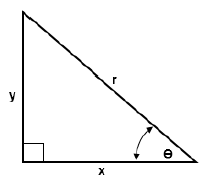
2.1 Sin θ = y
r
2.2 Sin θ = x
r
2. 3 Sin θ = y
x
2.4 r2 = x2 + y2
3 TEMPLATES AND DEVELOPMENTS
3.1 Mean Ø = Outside Ø - Plate thickness
OR Mean Ø = Inside Ø + Plate thickness
3.2 Mean circumference = π x Mean Ø
(where Ø = diameter)
5.CONCLUSION
This Examination Guidelines document is meant to articulate the assessment aspirations espoused in the CAPS document. It is therefore not a substitute for the CAPS document which teachers should teach to.
Qualitative curriculum coverage as enunciated in the CAPS cannot be over-emphasised.