CIVIL TECHNOLOGY PAPER GRADE 12 QUESTIONS - NSC PAST PAPERS AND MEMOS NOVEMBER 2016
Share via Whatsapp Join our WhatsApp Group Join our Telegram GroupCIVIL TECHNOLOGY PAPER
GRADE 12
NSC EXAM PAPERS AND MEMOS
NOVEMBER 2016
REQUIREMENTS:
- Drawing instruments
- A non-programmable calculator
- ANSWER BOOK
INSTRUCTIONS AND INFORMATION
- This question paper consists of SIX questions.
- Answer ALL the questions.
- Answer each question as a whole. Do NOT separate subsections of questions.
- Start the answer to EACH question on a NEW page.
- Do NOT write in the margins of the ANSWER BOOK.
- You may use sketches to illustrate your answers.
- Write ALL calculations and answers in the ANSWER BOOK or on the attached ANSWER SHEETS.
- Use the mark allocation as a guide to the length of your answers.
- Make drawings and sketches in pencil, fully dimensioned and neatly finished off with descriptive titles and notes to conform to the SANS/SABS Code of Practice for Building Drawings.
- For the purpose of this question paper, the size of a brick should be taken as 220 mm x 110 mm x 75 mm.
- Use your own discretion where dimensions and/or details have been omitted.
- Answer QUESTIONS 1.3, 1.8.2, 3.11, 4.3, 5.2, 5.3, 6.1 and 6.2 on the attached ANSWER SHEETS using drawing instruments where necessary.
- Write your CENTRE NUMBER and EXAMINATION NUMBER on every ANSWER SHEET and hand them in with your ANSWER BOOK, whether you have used them or not.
- Due to electronic transfer, drawings in the question paper are NOT to scale.
QUESTIONS
QUESTION 1: CONSTRUCTION, SAFETY AND MATERIAL
1.1 FIGURE 1.1 below shows a person working on a building site. 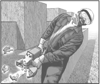
[Source: miryaglobalmedia]
FIGURE 1.1 (above)
1.1.1 Study FIGURE 1.1 and describe TWO aspects that the person should have considered to prevent this accident. (2)
1.1.2 Name TWO personal safety items that this person is wearing. (2)
1.1.3 Motivate why you think it is appropriate to wear ear protection when working with this power tool. (2)
1.1.4 Recommend ONE other important safety item that the person should have worn. (1)
1.2 Freshly cast concrete should be cured.
1.2.1 Describe what may be used to cure freshly cast concrete. (1)
1.2.2 State the duration of curing. (1)
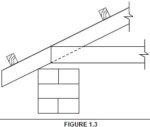
1.3 FIGURE 1.3 below shows an incomplete sectional view of a wall and roof construction.
Use ANSWER SHEET 1.3 and complete the sketch by drawing the following:
- Beam filling
- The wall plate
- Corrugated iron sheeting
- Label any TWO parts of the drawing.
 (6)
(6)
 (6)
(6) 1.4 Give TWO reasons why a roof covered with concrete tiles is more expensive than a roof covered with corrugated iron sheets. (2)
1.5 Recommend ONE material that you would use to finish a plastered wall in a bathroom. (1)
1.6 Give a reason for your answer to QUESTION 1.5. (1)
1.7 FIGURE 1.7 below shows a steel profile. 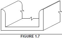
1.7.1 Identify the steel profile. (1)
1.7.2 Describe ONE effect that the weather will have on exposed, untreated steel profiles. (1)
1.7.3 How would you prevent the effect that you have described in QUESTION 1.7.2? (1)
1.7.4 State ONE use of the steel profile. (1)
1.8 FIGURE 1.8 below shows the front elevation of a T-junction of a half-brick wall with dead ends. 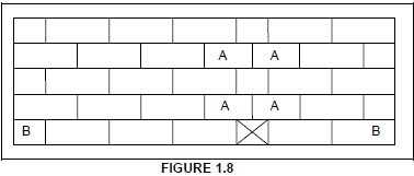
1.8.1 Identify bricks A. (1)
1.8.2 Use ANSWER SHEET 1.8.2 and project and draw, from the given front elevation, the plan course of a T-junction of course BB. The position of the T-junction is indicated with a cross (X) on the first course. (4)
1.9 Name ONE type of material that may be used for ceilings. (1)
1.10 Explain why cavity walls must have weep holes. (1)
[30]
QUESTION 2: ADVANCED CONSTRUCTION AND EQUIPMENT
Start this question on a NEW page.
2.1 Choose a description from COLUMN B that matches an item in COLUMN A. Write only the letter (A–M) next to the question number (2.1.1–2.1.10) in the ANSWER BOOK, for example 2.1.11 N.
COLUMN A | COLUMN B |
2.1.1 Key brick | A adjustable support that may be used individually or combined with frames to support formwork (10) |
2.2 FIGURE 2.2 below shows hand tools that are used on a site and in a workshop. Write down the name and ONE use of each of the tools next to the question number (2.2.1–2.2.4) in the ANSWER BOOK. (8)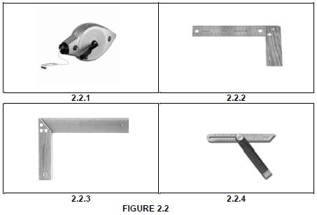
2.3 FIGURE 2.3 below shows an incomplete sectional view of a reinforced beam and column. 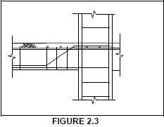
2.3.1 Predict TWO negative consequences of not having reinforcement in concrete. (2)
2.3.2 Explain why the main bar is placed at the bottom of the beam. (1)
2.3.3 Explain why the stirrups in a beam are placed closer to each other near the support. (1)
2.4 The accessories below are used to test fresh concrete:
- Mould with a diameter of 100 mm at the top, 200 mm at the bottom and a height of 300 mm
- Baseplate 3 mm thick and 600 mm by 600 mm
- Steel rod 16 mm in diameter and 600 mm long
2.4.1 Name the test that may be performed with the above accessories. (1)
2.4.2 Explain why it is necessary to conduct this test. (1)
2.4.3 How often must this test be carried out? (1)
2.5 Explain TWO advantages of cavity walls. (2)
2.6 FIGURE 2.6 below shows two concrete columns with defects caused by forces acting on them. 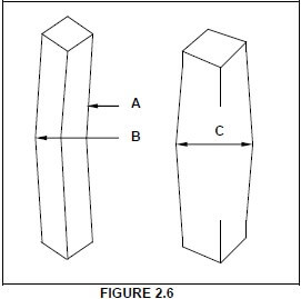
Name the type of forces responsible for the defects at A to C. (3)
2.7 FIGURE 2.7 below shows a type of formwork used in construction. 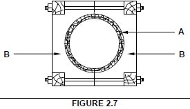
2.7.1 Identify the formwork in FIGURE 2.7. (1)
2.7.2 Recommend ONE material that may be placed on the inside around part A to give a smoother concrete finish. (1)
2.7.3 What is used to keep parts B together? (1)
2.7.4 Describe how you would prevent concrete from sticking to the inside of formwork. (1)
2.8 Distinguish between the installation of a rib and block floor and an in situ concrete floor regarding the duration of the installation. (1)
2.9 Make a neat, well-proportioned, two-dimensional sketch of a hollow block with a rib on either side of the block, as used in a rib and block floor construction. Show the reinforcement in the ribs. (5)
[40]
QUESTION 3: CIVIL SERVICES
Start this question on a NEW page.
3.1 Make neat freehand drawings to indicate the difference between a P-trap and an S-trap. (2)
3.2 Give the diameter of the PVC pipe that you would use for the wastewater at a sink. (1)
3.3 FIGURE 3.3 below shows a septic tank. Study the drawing and answer the questions that follow. 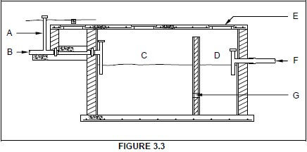
3.3.1 Label parts A to F. (6)
3.3.2 Describe what happens to the raw sewerage in C. (1)
3.3.3 Explain the purpose of G. (1)
3.3.4 What is the purpose of F? (1)
3.3.5 Describe the liquid level in C and D when the septic tank is filled to capacity. (1)
3.3.6 Explain why you may NOT direct water coming from a bath or sink into a septic tank. (1)
3.4 Describe the main function of a storm water system. (1)
3.5 Explain why storm water should NOT be directed into a sewerage system. (2)
3.6 Explain the purpose of a pressure-reducing valve as used in cold and hot water installations. (1)
3.7 Distinguish between the purpose of an elbow and the purpose of a tee coupler/T-fitting, as used in water pipe installation. (2)
3.8 The temperature of the water in your geyser is too high due to a faulty part. Name the faulty part that will cause the water to overheat. (1)
3.9 What type of geyser would you use when the pressure of the incoming water from the municipality is low? (1)
3.10 The inside tray of a solar panel is painted a specific colour. Name the colour and give a reason for using this specific colour. (2)
3.11 FIGURE 3.11 on ANSWER SHEET 3.11 shows part of a vertical section through a building.
Use ANSWER SHEET 3.11.
3.11.1 Identify A and B. (2)
3.11.2 Complete the drawing by showing the following on the drawing:
- The incoming electricity cable in a kick pipe connected to a meter box at C
- Distribution board at D
- The conduit for the connection from the meter box to the distribution board at D (4)
[30]
QUESTION 4: QUANTITIES, MATERIALS AND JOINING
Start this question on a NEW page.
4.1 FIGURE 4.1 below shows the front view of a hollow-core flush panel door. Study the drawing and complete the incomplete cutting list. Write down the answer next to the question number (4.1.1 to 4.1.7) in the ANSWER BOOK. 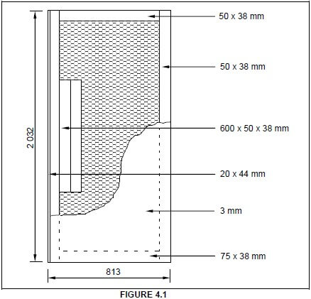
MEMBER | QUANTITY | UNIT | LENGTH | WIDTH | THICKNESS | MATERIAL |
4.1.1 | 2 | mm | 2 032 | 50 | 38 | SA pine |
Top rail | 1 | mm | 693 | 4.1.2 | 38 | SA pine |
Lock block | 2 | mm | 4.1.3 | 50 | 38 | SA pine |
Plywood panel | 1 | mm | 2 032 | 813 | 4.1.4 | Plywood |
Bottom rail | 1 | mm | 4.1.5 | 50 | 38 | SA pine |
Cardboard door filling | 1 | mm | 4.1.6 | 690 | 38 | Cardboard |
Edging | 1 | mm | 2 032 | 44 | 4.1.7 | Meranti |
(7)
4.2 Various options are provided as possible answers to the following questions. Choose the answer and write only the letter (A–D) next to the question number (4.2.1–4.2.7) in the ANSWER BOOK, for example 4.2.8 C.
4.2.1 When joining copper pipes using the capillary method, you will ... the two pipes together.
- weld
- solder
- glue
- tape (1)
4.2.2 You can join ... pipes using the capillary method.
- copper
- copper and PVC
- copper and galvanised
- copper, PVC and galvanised (1)
4.2.3 When fixing a cornice to a wall, you will use ...
- panel pins.
- wire nails.
- steel cut nails.
- steel/masonry nail. (1)
4.2.4 A compression joint may be used to join ... pipes.
- copper
- PVC
- galvanised
- All of the above (1)
4.2.5 ... is used for joining roof trusses to brickwork.
- Hoop iron
- Building line
- Cement
- None of the above-mentioned (1)
4.2.6 ... may be used to join polyethylene pipes.
- Wood glue
- Insulation tape
- Contact glue
- PVC weld solvent (1)
4.2.7 Type of screw used when the head of the screw must be flush to the surface of the timber:
- Coach screw
- Round head screw
- Countersunk head screw
- Round head countersunk screw (1)
4.3 FIGURE 4.3 below shows the floor plan of a storeroom of which the walls need to be plastered. 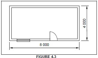
SPECIFICATIONS:
- Outside measurements of the storeroom: 8 000 mm x 4 000 mm
- Height of the walls: 2 700 mm
- Thickness of the walls: 220 mm
- Thickness of the plaster: 12 mm
- Size of the window: 1 200 mm x 900 mm
- Size of the door opening: 2 100 mm x 900 mm
Use ANSWER SHEET 4.3 and calculate the:
4.3.1 Total area of the inside of the building that must be plastered. Ignore the reveals. (13)
4.3.2 Volume of plaster needed for the internal walls (3)
[30]
QUESTION 5: APPLIED MECHANICS
Start this question on a NEW page.
5.1 FIGURE 5.1 below shows a shaped lamina with a square hole. All dimensions are in millimetres.
Study the lamina and answer the questions that follow by writing only the answer with the unit next to the question number (5.1.1–5.1.7) in the ANSWER BOOK, for example 5.1.8 2 900 mm².
HINT: Use the formulae on the FORMULA SHEET.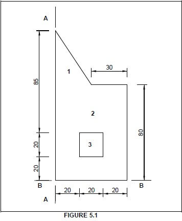
5.1.1 Calculate the area of part 1. (1)
5.1.2 Calculate the area of part 2 without the hole. (1)
5.1.3 Calculate the area of part 3. (1)
5.1.4 Calculate the total area of the lamina. (1)
5.1.5 Calculate the position of the centroid of part 2 from A–A. (1)
5.1.6 Calculate the position of the centroid of part 1 from B–B. (2)
5.1.7 Calculate the position of the centroid of part 2 from B–B. (1)
5.2 ANSWER SHEET 5.2 shows TWO diagrams of a cantilever frame. Use ANSWER SHEET 5.2 to answer the following questions.
5.2.1 Name DIAGRAMS A and B. (2)
5.2.2 On DIAGRAM A, indicate the nature of the forces in each member by means of arrows. (4)
5.2.3 Complete the table by indicating the nature and magnitude of the forces. (Deduce the information from the drawings given.) (6)
5.3 FIGURE 5.3 below shows the space diagram of a beam with a span of 10 metres with two point loads and a uniformly distributed load. Study the diagram and answer the questions that follow. 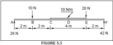
5.3.1 Deduce from FIGURE 5.3 the value of the shear forces at A, B, C, E and F and draw the shear force diagram on ANSWER SHEET 5.3. Indicate the value of the shear forces on the diagram.
Use scale 1 mm = 1 N. (7)
5.3.2 Calculate the bending moment at D. (3)
[30]
QUESTION 6: GRAPHICS AND COMMUNICATION
6.1 FIGURE 6.1 below shows the site plan of a proposed dwelling. Study the drawing and complete the table on ANSWER SHEET 6.1. 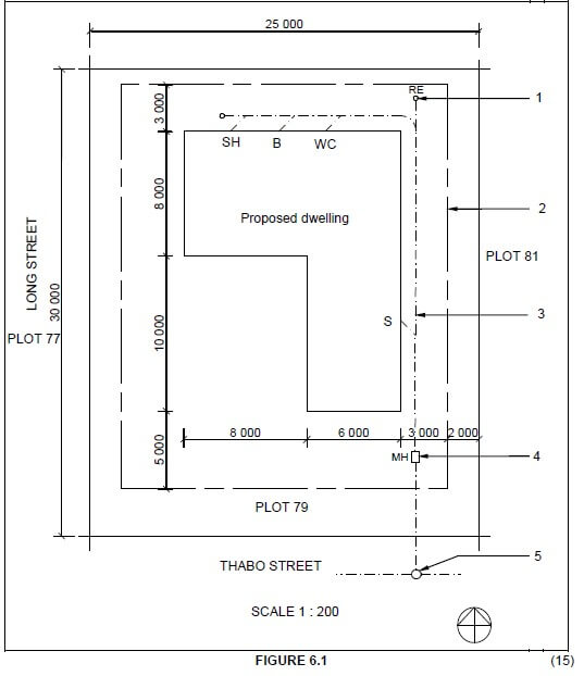 (15)
(15)
6.2 FIGURE 6.2 below shows a line diagram of the floor plan of an office with a storeroom. 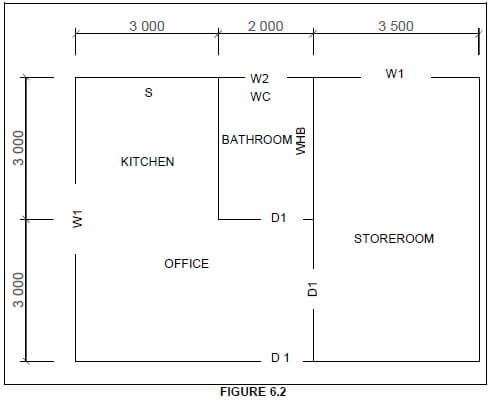
Study FIGURE 6.2 and develop and draw, on ANSWER SHEET 6.2, to scale 1 : 50, the FLOOR PLAN of the building. Use the specifications below and on the next page. (Use the assessment criteria on ANSWER SHEET 6.2 as a guideline for your drawing.)
SPECIFICATIONS:
- The measurements indicated on the drawing are the inside measurements of each room.
- Windows and doors:
WINDOWS AND DOORS | WIDTH | HEIGHT |
Window 1 (W1) | 1 500 | 1 200 |
Window 2 (W2) | 900 | 600 |
Door 1 (D1) | 900 | 2 100 |
- All windows are positioned in the middle of the external wall of each room.
- All doors are positioned 300 mm from the wall to the right of the door.
- The door of the storeroom is positioned in the middle of the wall shared by the office and the bathroom.
- All external walls of the house are 220 mm wide.
- All internal walls are 110 mm wide.
The following must also be shown on the floor plan: - The drawing symbols for a hand basin, water closet and double-bowl sink, as indicated by the abbreviations on the line diagram
- The total internal dimensions of the office on the western side of the building
- The dimensions of the thicknesses of the walls and sizes of rooms on the western side of the office
- Labels for the floor coverings for each room
- The windows and doors in the spaces, as indicated on the line diagram
THREE marks will be allocated for the application of the scale.
Start the drawing from corner A, as indicated in the bottom left-hand corner of ANSWER SHEET 6.2. (25)
[40]
TOTAL: 200
CENTRE NUMBER: |
EXAMINATION NUMBER: |
ANSWER SHEET 1.3 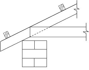
ASSESSMENT CRITERIA | MARK | CANDIDATE'S MARK |
Roof covering correctly drawn | 1 | |
Beam filling correctly drawn | 2 | |
Wall plate correctly drawn | 1 | |
Any two labels | 2 | |
TOTAL | 6 |
CENTRE NUMBER: |
EXAMINATION NUMBER: |
ANSWER SHEET 1.8.2
1.8.2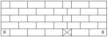

ASSESSMENT CRITERIA | MARK | CANDIDATE'S MARK |
Stretcher course | 2 | |
Header course | 1 | |
Correctness of T-junction | 1 | |
TOTAL | 4 |
CENTRE NUMBER: |
EXAMINATION NUMBER: |
ANSWER SHEET 3.11 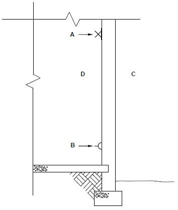
A: ________________________________ (1)
B: ________________________________ (1)
ASSESSMENT CRITERIA | MARK | CANDIDATE'S MARK |
Incoming cable | 2 | |
Meter box | 1 | |
Distribution board | 1 | |
TOTAL | 4 |
CENTRE NUMBER: |
EXAMINATION NUMBER: |
ANSWER SHEET 4.3
Complete your answers in the spaces indicated with _____________.
4.3.1
A | B | C | D |
Area to be plastered: | |||
Length of ONE short wall: | |||
= ______ – 2/________ = ______ | |||
Length of ONE long wall: | |||
= _____ – 2/________ = _______ | |||
Total length of one short and one long wall | |||
= _____________ + _____________ = _____________ (3) | |||
2/ | _______ | Area of internal walls before deductions: | |
_____ | _____ m2 | (2) | |
1/ | _______ | Area of window opening: | |
_______ | _____ m2 | (2) | |
1/ | _______ | Area of door opening: | |
_____ | _____ m2 | (2) | |
Total wall area to be plastered | |||
= _____________ - _____________ - ______________ | |||
=_______________ m2 (2) |
4.3.2 (3)
Volume of plaster needed: | |||
1/ | ______ | ||
______ | ________ |
CENTRE NUMBER: |
EXAMINATION NUMBER: |
ANSWER SHEET 5.2 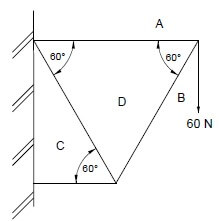
DIAGRAM A __________________________ (1) 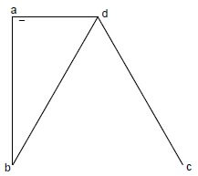
DIAGRAM B ________________________ (1)
SCALE: 1 mm = 1 N
MEMBER | NATURE | MAGNITUDE |
BC | ||
CD | --- | |
DA | ||
BD | --- |
(6)
Tolerance of 1 N to either side
CENTRE NUMBER: |
EXAMINATION NUMBER: |
ANSWER SHEET 5.3 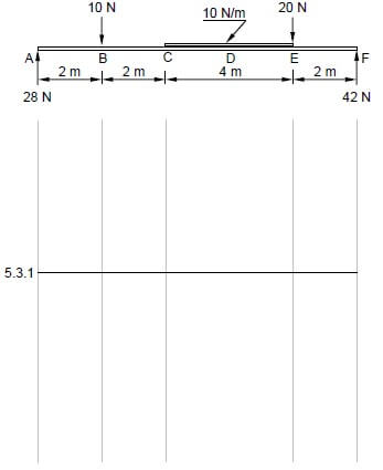
ASSESSMENT CRITERIA | MARKS | CANDIDATE'S MARK |
Drawing correct | 5 | |
Indicate all values of shear forces on drawing | 1 | |
Correct application of scale | 1 | |
TOTAL | 7 |
CENTRE NUMBER: |
EXAMINATION NUMBER: |
ANSWER SHEET 6.1
NO. | QUESTIONS | ANSWERS | MARKS |
1 | Name the scale used for the site plan. | 1 | |
2 | State the colour that you would use to indicate the proposed dwelling on the site plan. | 1 | |
3 | Identify number 1. | 1 | |
4 | Identify the line at number 2. | 1 | |
5 | Identify number 3. | 1 | |
6 | Determine the distance from the boundary line to the proposed dwelling to the right of the building. | 1 | |
7 | Identify number 4. | 1 | |
8 | Identify number 5. | 1 | |
9 | Draw the roof line of a hipped roof for the building. | 4 | |
10 | Calculate the perimeter of the proposed dwelling. | 2 | |
11 | Which elevation will be closest to Long Street? | 1 | |
TOTAL | 15 |
CENTRE NUMBER: |
EXAMINATION NUMBER: |
ANSWER SHEET 6.2
ASSESSMENT CRITERIA | MARKS | LM |
External walls | 4 | |
Internal walls | 3 | |
Windows | 3 | |
Doors | 3 | |
Wash basin | 1 | |
Water closet | 1 | |
Double-bowl sink | 1 | |
Dimensions | 4 | |
Floor coverings | 2 | |
Application of scale One or two incorrect = 3 Three or four incorrect = 2 More than five incorrect = 1 No measurement correct = 0 | 3 | |
TOTAL | 25 |
FORMULA SHEET
IMPORTANT ABBREVIATIONS
SYMBOL | DESCRIPTION | SYMBOL | DESCRIPTION | SYMBOL | DESCRIPTION |
c | Centroid | b | Breadth/Width | r | Radius |
ℓ | Length | s | Side | A | Area |
FORMULAE
AREA OF | FORMULA (in words) | FORMULA (in symbols) | FORMULA FOR THE POSITION OF CENTROIDS | |
X-axis | Y-axis | |||
Square | side × side | s × s | s/2 | s/2 |
Rectangle | length × breadth | ℓ × b | ℓ /2 | b/2 |
Right-angled triangle | ½ x base × height | ½b × h | b/3 | h/3 |
Equilateral triangle/ Isosceles triangle | ½ x base × height | ½b × h | b/2 | h/3 |
Position of centroid = (A1×d) ± (A2 ×d)
Total area
OR
Y = ∑Ay
∑A
OR
X = ∑Ax
∑A