MECHANICAL TECHNOLOGY(WELDING & METALWORK) GRADE 12 MEMORANDUM - NSC PAST PAPERS AND MEMOS NOVEMBER 2021
Share via Whatsapp Join our WhatsApp Group Join our Telegram GroupMARKING GUIDELINES
QUESTION 1: MULTIPLE-CHOICE QUESTIONS (GENERIC)
1.1 B (1)
1.2 A (1)
1.3 D (1)
1.4 A / C (1)
1.5 A (1)
1.6 C (1) [6]
QUESTION 2: SAFETY (GENERIC)
2.1 First-aid applications to an open wound:
- Use surgical gloves.
- Do not remove anything that is stuck to the wound.
- Never use sticky plaster on the wound.
- Cover the wound with a clean, lint-free cloth.
- Avoid using any oily substances or lotions on wounds.
- If necessary, cool wounds with cold water.
- Apply pressure to prevent blood loss if necessary.
- Avoid contact with blood from patient.
- If the wound is on your arm, raise the arm above your head to stop the bleeding.
(Any 2 x 1) (2)
2.2 Surface grinder: (Already switched on)
- Never leave the grinder unattended.
- Switch off the machine when leaving.
- Don’t try to stop revolving emery wheel with your hand.
- Don’t adjust the machine while working.
- Don’t open any guard while the machine is on.
- Do not force the grinding wheel on to the work piece.
- Approach the work piece slowly and evenly.
- Don’t clean the machine while working.
- Do not put hands near the work piece when grinder is in motion.
- Don’t clean or adjust the machine while working.
- Check for oil on the floor while working (spilling of cutting fluid on floor while working)
- Check that the grinding wheel is running evenly.
(Any 2 x 1) (2)
2.3 Gauges calibrated:
- To ensure accurate readings.
- To prevent overloading.
(Any 1 x 1) (1)
2.4 Finger protectors’ hazards on power driven guillotines:
- The finger protector prevents the hazards of getting the fingers cut by the blades.
- To be crushed by the hold-downs. (2)
2.5 Welding or flame cutting operation safety:
- An operator has been instructed on how to use the equipment safely.
- A workplace is effectively partitioned off.
- An operator uses protective equipment.
- Ensure that all equipment is in safe working condition.
- Ensure that here are no flammable materials around the welding area.
- Weld area must be well ventilated.
- Fire extinguisher must be in close proximity.
(Any 2 x 1) (2)
2.6 Workshop layout:
- Product layout. (1)
[10]
QUESTION 3: MATERIALS (GENERIC)
3.1 File test:
3.1.1 Difficult (1)
3.1.2 Easy (1)
3.1.3 Difficult (1)
3.2 Heat treatment:
- A. – Grain growth.
- B. – Recrystallisation.
- C. – Recovery. (3)
3.3 Bending test:
- Bend the test piece through a specific angle or around a mandrel or bar, having a defined radius, until a rupture in the metal occurs.
- Place the material in a vice and bend it then observe the ductility of the material.
(Any 1 x 3) (3)
3.4 Purpose of case hardening:
- Creates a hard surface with a tough core. (2)
3.5 Quenching media for hardening:
- Water
- Brine (saltwater)
- Oil
- Soluble oil and water
- Nitrogen air-infused air
(Any 3 x 1) (3)
[14]
QUESTION 4: MULTIPLE-CHOICE QUESTIONS (SPECIFIC)
4.1 B (1)
4.2 B (1)
4.3 D (1)
4.4 C (1)
4.5 D (1)
4.6 A (1)
4.7 A (1)
4.8 B (1)
4.9 C (1)
4.10 B (1)
4.11 C (1)
4.12 B (1)
4.13 A (1)
4.14 D (1)
[14]
QUESTION 5: TERMINOLOGY (TEMPLATES) (SPECIFIC)
5.1 Dimensions of the material:
5.1.1
- Mean Ø = Outside Ø = Plate Thickness
= 960 - 60 ?
= 900 mm ? (2)
5.1.2
- \Mean circumference = π x Mean Ø
= π x 900 ?
= 2827,43 mm ?
Round off to 2827 mm ? (3)
5.2 Welding symbols:
5.2.1 - 5.2.5
Each @ (2)
5.3 Templates:
5.3.1 Flange template (1)
5.3.2 Strip template (1)
5.3.3 Web template (1)
5.4 Hand tools: (Due to the large number of alternatives, marker discretion must be used - discuss with IM).
- Hand saws
- Chisels
- Plane
- Handdrill and drill bits
- Steel measuring tape
- Straight edge
- Compass
- Trammel pins
- Carpenter’s square
- Protractor
- Chalk line
- Steel rule
- Hammers
- Centre punch
- Callipers
- Scribe
- Combination square
- Spirit level
- Trammel
(Any 3 x 1) (3)
5.5 Template loft machines: (Due to the large number of alternatives, marker discretion must be used - discuss with IM).
- Circular saw
- Planer
- Drilling machine
- Jig saw
- Sanding machine
- Shears for cutting cardboard
- Welding machine
- Angle grinder
- Bench grinder
- Guillotine
- Cut–off power saw
(Any 2 x 1) (2)
[23]
QUESTION 6: TOOLS AND EQUIPMENT (SPECIFIC)
6.1 Operating principles of a resistance welding machine:
- Current flows through a resistance to fuse plates together. ?
- Two copper electrodes are pressed against the plates. ?
- Heavy current is passed between the electrodes. ?
- High resistance causes intense heat at the point. ?
- The two plates melt and fuse together, forming a weld nugget or spot weld. ? (5)
6.2 Arc welding:
6.2.1
- A. Arc welding machine / Power source / invertor. ?
- B. Earth clamp / “skelm” ?
- C. Electrode / Rod / welding rod ?
- D. Electrode holder (4)
6.2.2
- Holds the electrode.
- Insulate the person welding
- Provide current to the electrode
- Used with electrode to weld
(Any 1 x 1) (1)
6.3 Cutting of threads:
- Secure the die in die wrench/stock and set die square to the shaft to be cut.
- Rotate the die through half a turn in a clockwise direction to cut the thread and then turn back a quarter of a turn to break off waste.
- Continue process until the die has reached the required length of thread and adjust the centre and side screws until desired thread fit is achieved. (6)
6.4 Advantages of using a punch machine:
- Can punch holes faster.
- Punch various hole profiles
- Less effort is needed
(Any 1 x 1) (1)
6.5 Pyramid rollers
- Rolling sheet metal.
- Used to roll round bars
(Any 1 x 1) (1)
[18]
QUESTION 7: FORCES (SPECIFIC)
7.1 Beams:
7.1.1 Calculating reactions:
Taking moments about RL:
- RRx10 = (80?x 3 ) + (60x 5) + (100x 7)
= 240 + 300 + 700
RR = 1240/10
= 124 N ?
Taking moments about RR:
- RLx10 = (100 ?x3 ) + (60x5 ) + (80 x 7 )
= 300 + 300 + 560
RL = 1160/10
=116 N ? (8)
7.1.2 Calculating bending moments: Bending moments at B, C and D:
- BMB =(116 x 3 )
= 348Nm ?
BMC =(116 x 5 ) - (80 x 2 )
= 420Nm ?
BMD = (116 x 7 ) - (80 x 4 ) - (60 x 2 )
= 372Nm ? (3)
7.1. 3 Bending moment diagram: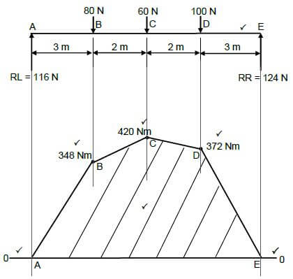
(7)
NOTE: Draw the bending moment diagram to scale for marking purposes.
7.2 Stress and Strain:
7.2.1 Diameter of a bar: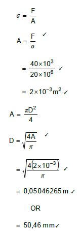
(6)
7.2.2 Strain: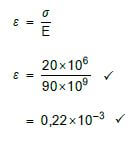
(2)
7.2.3 Change in length: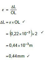
(3)
7.3 Stress and strain diagram:
- A: Limit of proportionality ?
- B: Elastic limit ?
- C: Yield point ?
- D: Maximum stress ?
- E: Break stress ? (5)
7.4 Simple frame:
7.4.1 Vector/Force diagram: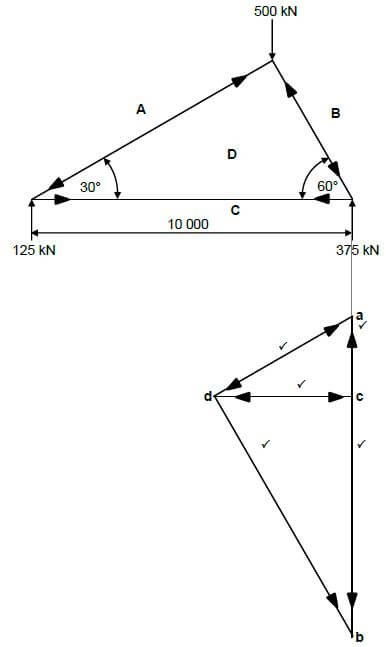
(5)
7.4.2 Magnitude and nature of force:
Member | Force | Nature |
AD | 250 kN | Strut |
BD | 433 kN | Strut |
CD | 216 kN | Tie |
(6)
[45]
QUESTION 8: JOINING METHODS (INSPECTION OF WELDS) (SPECIFIC)
8.1 Arc welding aspects:
- Rate of rod burning and the progress of the weld
- Amount of penetration and fusion.
- Observe for welding defects while welding
- The sound of the arc indicating correct current and voltage for the particular weld.
- Angle of electrode.
- Arc length.
- Size of molten pool while welding
(Any 3 x 1) (3)
8.2 Centreline cracks:
- Aiming at width to depth ratio of 1:1.
- Decreasing the current to prevent excess penetration.
- Decreasing welding voltage
- Slowing travel speed to achieve a flat to convex weld surface.
- Use clamping device.
- Pre – Heating
- Use of correct electrode
(Any 2 x 1) (2)
8.3 Welding defects:
8.3.1 Lack of fusion:
- Travel speed is too slow.
- Wide weld joint.
- Weld current too low.
- Too big weaving action.
- Included angle not correct.
- Contaminated parent metal surface
- Weld metal not permitted to roll in front of arc.
- Arc not kept on leading edge of molten pool.
- Travel speed too fast.
- Excessive mill scale (iron oxide)
(Any 2 x 1) (2)
8.3.2 Porosity:
- Contaminated weld surface.
- Wet or dirty electrodes.
- Shielding gas supply is interrupted.
- Welding in windy conditions.
(Any 2 x 1) (2)
8.3.3 Incomplete penetration:
- Welding current too low.
- Welding speed too fast.
- Incorrect electrode angle.
- Poor joint preparation.
- Insufficient root gap.
- Electrode too big.
- Too long arc
- Contaminated weld surface.
(Any 2 x 1) (2)
8.4 Setting oxy-acetylene torch flame to a neutral flame:
- Open acetylene torch valve ¼ turns or less and ignite.
- Adjust the acetylene torch valve further until the black smoke disappears.
- Open oxygen torch valve until the flame is no longer burning yellow.
- Inner cone of the flame must be rounded.
(Any 3 x 1) (3)
8.5 Guided bend test:
- Specimen is placed across the supports of the die.
- Apply force to the specimen to bend into shape of the die.
- Determine the percentage of elongation of the weld metal. (3)
8.6 Free bend test:
- Determine the ductility of the weld.
- Determine the ductility of the heat – affected area adjacent to the weld.
- Determine the percentage of elongation
(Any 2 x 1) (2)
8.7 Types of dye:
- Type A: Fluorescent that emits visible light when viewed using a Black light.
- Type B: Brightly coloured liquid dyes that can be inspected in regular light. (2)
8.8 Nick-break test:
- Determines internal quality of the weld metal.
- Reveals internal defects such as slag inclusions, porosity and lack of fusion.
(Any 1 x 2) (2)
[23]
QUESTION 9: JOINING METHODS (STRESS AND DISTORTION) (SPECIFIC)
9.1 Causes of residual stress in welds:
- Heat present in the weld.
- Qualities of parent metal, filler rod or electrode.
- Shape and size of weld.
- Number of successive weld runs.
- Comparative weight of weld and parent metal.
- Type of welding joint used.
- Welding method used to mitigate stress and distortion.
- Type of structure of neighbouring joints.
- Freeness of joint to be able to expand and contract.
- Rate of cooling.
- Stresses already present in the parent metal.
(Any 2 x 1) (2)
9.2 Factors of cooling rate:
- Size of work piece.
- Weld thickness.
- Thermal conductive properties of parent metal.
(Any 3 x 1) (3)
9.3 Effect of cold working:
- The effect of cold working is to break down the crystal structure elongating the grains.
- An elongated and distorted crystal structure of this kind gives the metal greater hardness and tensile strength.
- Reduces ductility.
- Referred to as work hardening. (4)
9.4 Effects of welding speed on distortion:
- Increase in welding speed increases distortion due to larger flame in oxy-acetylene welding.
- Larger diameter electrode requires increased current causing more localised heat.
- Causing more residual stress.
- Causing more distortion.
(Any 3 x 1) (3)
9.5 Quenching media:
- Water
- Oil
- Brine
- Liquid salts
- Sand
- Air
- Ash
- Lime
- Molten lead
- Nitrogen air-infused air
(Any 3 x 1) (3)
9.6 Reducing welding distortion:
- Do not over-weld.
- Intermittent welding.
- Place welds near the neutral axis.
- Use a few passes as possible.
- Use back step welding.
- Anticipate the shrinkage forces.
- Use clamps, jigs and fixtures.
- Use strongbacks.
- Heating metal before welding. (pre- heating)
- Slowing the cooling rate
(Any 3 x 1) (3)
[18]
QUESTION 10: MAINTENANCE (SPECIFIC)
10.1 Locking out of machine:
- Isolation switches must be switched off. ?
- The only key to the lock is in possession of the person carrying out the maintenance / Each maintenance person must have own lock. ? (2)
10.2 Tagging plates:
- More than one technician can lock out machine simultaneously. ? (1)
10.3 Minor service for a power-driven guillotine:
- The minor service is designed to minimise ? major mechanical and electrical failures. ? (2)
10.4 Cutting fluid:
- Keep the blade cool.?
- Keep the work piece cool ?
- Prolong the life span of the blade ?
- Washes cuttings away ?
- Improves cutting efficiency ?
- Reduces friction during cutting process. ?
- Better finish given to workpiece. ?
- Also prevents further corrosion. ?
(Any 2 x 1) (2)
10.5 Overloading a rolling machine:
- Limit the life span of components ?
- Can result in costly damage ?
- Damage to bearings/bushes ?
- Damage to gearbox ?
- Damage to motor ?
(Any 1 x 1) (1)
[8]
QUESTION 11: TERMINOLOGY (DEVELOPMENTS) (SPECIFIC)
11.1 True length of AC:
- AC2 = AB2 + BC2
but BC = 90 - 50
2
= 40/2
= 20 mm
AC2 = AB2 + BC2
= 502 + 202
AC =√ 2500 + 400
= 53,85mm
= 54mm (6)
11.2 Development:
- Square/rectangle ? to round ? transformer / transition piece / on centre. ? (3)
11.3 Square to rectangle on centre hopper:
11.3.1 True length of A-1:
- A - 1 = √2002 + 1302 + 5002
= √40000 + 16900 + 250000
= √306900
= 553,99
= 554 mm (4)
11.3.2 True length of C-2:
- C - 2 = √4702 + 2002 + 5002
= √220900 + 40000 + 250000
= √510900
= 714,77
= 715 mm (4)
11.4 Hoppers:
11.4.1 Square to rectangle ? hopper off centre ? (2)
11.4.2 Square to square ? hopper on centre ? (2)
[21]
TOTAL: 200