MECHANICAL TECHNOLOGY(FITTING & MACHINING) GRADE 12 MEMORANDUM - NSC PAST PAPERS AND MEMOS NOVEMBER 2021
Share via Whatsapp Join our WhatsApp Group Join our Telegram GroupMARKING GUIDELINES
QUESTION 1: MULTIPLE-CHOICE QUESTIONS (GENERIC)
1.1 B (1)
1.2 A (1)
1.3 D (1)
1.4 A / C (1)
1.5 A (1)
1.6 C (1)
[6]
QUESTION 2: SAFETY (GENERIC)
2.1 First-aid applications to an open wound:
- Use surgical gloves.
- Do not remove anything that is stuck to the wound.
- Never use sticky plaster on the wound.
- Cover the wound with a clean, lint-free cloth.
- Avoid using any oily substances or lotions on wounds.
- If necessary, cool wounds with cold water.
- Apply pressure to prevent blood loss if necessary.
- Avoid contact with blood from patient.
- If the wound is on your arm, raise the arm above your head to stop the bleeding.
(Any 2 x 1) (2)
2.2 Surface grinder: (Already switched on)
- Never leave the grinder unattended.
- Switch off the machine when leaving.
- Don’t try to stop revolving emery wheel with your hand.
- Don’t adjust the machine while working.
- Don’t open any guard while the machine is on.
- Do not force the grinding wheel on to the work piece.
- Approach the work piece slowly and evenly.
- Don’t clean the machine while working.
- Do not put hands near the work piece when grinder is in motion.
- Don’t clean or adjust the machine while working.
- Check for oil on the floor while working (spilling of cutting fluid on floor while working)
- Check that he grinding wheel is running evenly.
(Any 2 x 1) (2)
2.3 Gauges calibrated:
- To ensure accurate readings.
- To prevent overloading.
(Any 1 x 1) (1)
2.4 Finger protectors’ hazards on power driven guillotines:
- The finger protector prevents the hazards of getting the fingers cut by the blades.
- To be crushed by the hold-downs. (2)
2.5 Welding or flame cutting operation safety:
- An operator has been instructed on how to use the equipment safely.
- A workplace is effectively partitioned off.
- An operator uses protective equipment.
- Ensure that all equipment is in safe working condition.
- Ensure that here are no flammable materials around the welding area.
- Weld area must be well ventilated.
- Fire extinguisher must be in close proximity.
(Any 2 x 1) (2)
2.6 Workshop layout:
- Product layout. (1)
[10]
QUESTION 3: MATERIALS (GENERIC)
3.1 File test:
3.1.1 Difficult (1)
3.1.2 Easy (1)
3.1.3 Difficult (1)
3.2 Heat treatment:
- A. – Grain growth.
- B. – Recrystallisation.
- C. – Recovery. (3)
3.3 Bending test:
- Bend the test piece through a specific angle or around a mandrel or bar, having a defined radius, until a rupture in the metal occurs.
- Place the material in a vice and bend it then observe the ductility of the material.
(Any 1 x 3) (3)
3.4 Purpose of case hardening:
- Creates a hard surface with a tough core. (2)
3.5 Quenching media:
- Water
- Brine (saltwater)
- Oil
- Soluble oil and water
- Nitrogen air-infused air
(Any 3 x 1) (3)
[14]
QUESTION 4: MULTIPLE-CHOICE QUESTIONS (SPECIFIC)
4.1 C (1)
4.2 B (1)
4.3 A (1)
4.4 A (1)
4.5 D (1)
4.6 D (1)
4.7 C (1)
4.8 C (1)
4.9 B / D (1)
4.10 D (1)
4.11 A (1)
4.12 A (1)
4.13 B (1)
4.14 D (1)
[14]
QUESTION 5: TERMINOLOGY (LATHE AND MILLING MACHINE) (SPECIFIC)
5.1 Advantages of compound slide method:
- Tapers with large angles can be cut.
- External and internal tapers can be cut.
- The set-up is simple.
(Any 2 x 1) (2)
5.2 Taper cutting:
5.2.1 Length of taper: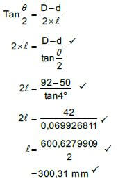
(5)
5.2.2 Tailstock set-over: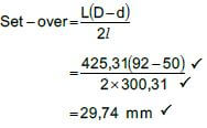
(3)
5.3 Key ways:
5.3.1 Width:
Width = D/4
Width = 75 ?
= 18,75 mm ? (2)
5.3.2 Thickness:
Thickness = D/6
Thickness = 75/6
= 12,50 mm ? (2)
5.3.3 Length:
Length= 1,5 x diameterof shaft
= 1,5 x 75
= 112,50 mm ? (2)
5.4 Disadvantages of down-cut milling:
- Vibration in the arbor is unavoidable.
- A fine feed must be used.
- When milling material with hard scale, the cutter teeth come directly in contact with the scale, which can damage the cutter.
- The process is time consuming.
(Any 2 x 1) (2)
[18]
QUESTION 6: TERMINOLOGY (INDEXING) (SPECIFIC)
6.1 Gear terminology:
6.1.1 Pitch-circle diameter:
- PCD = m x T
= 1,5 x 200 ? OR CP = m x π
= 300 mm? = 1,5 x π
= 4,71mm ?
PCD = CP x T
π
= 4,71 x 200
π
= 299,85mm ? (2)
6.1.2 Dedendum:
- Dedendum= 1,157 x m Dedendum= 1,25 x m
= 1,157 x 1,5 ? OR = 1,25 x 1,5
= 1,74 mm ? = 1,88 mm ? (2)
6.1.3 Outside diameter:
- OD = PCD + 2 x m OD = m(T + 2)
= 300 + 2(1,5) ? OR = 1,5(200 + 2) ?
= 303 mm ? = 303 mm ? (2)
6.1.4 Working depth:
- WD = 2 x m WD = 2 x a
= 2 x 1,5 ? OR = 2 x 1,5
= 3 mm ? = 3 mm ? (2)
6.2 Dovetails:
- W = 210 + 2(DE)
m = W – 2(AC) – 2(R)
6.2.1 Maximum width distance of dove tail: (W)
Calculate DE or y:
- tanθ = DE
AD
DE = tanθ x AD ?
= tan30°x 45
= 25,98 mm ?
W = 210 + 2(DE) ?
= 210 + 2(25,98) ?
= 210 + 51,96
= 261,96 mm ? (6)
6.2.2 Distance between the rollers: (m)
Calculate AC or x:
- Tanθ = BC
AC
AC = BC ?
Tanθ
AC = 17 ?
Tan30º
= 29,44mm ?
m = W - 2(AC) - 2(R) ?
= 261,96 - 2(29,44) - 2(17) ?
= 261,96 - 58,88 - 34
= 169,08 mm ? (6)
6.3 Milling of spur gear:
6.3.1 Indexing:
- Indexing = 40 = 40
N 137
= 40 = 40
A 140
= 4 x 2
14 2
= 8 ?
28 - Indexing: 8 holeson a 28 - hole circle ?
OR
- 12 holeson a 42 - hole circle ?
OR
- 14 holes on a 49-hole circle. ? (3)
6.3.2 Change gears: (Markers to note alternative answers and calculations to award full marks if the answer is correct)
- Dr=( A - n) x 40
Dn A
Dr =(140 - 137) x 40 ?
Dn 140
= 3 x 40
140
= 120/140
= 12/14 x 2/2
Dr = 24 OR 48 ?
Dn 28 ? 56 ?(5)
[28]
QUESTION 7: TOOLS AND EQUIPMENT (SPECIFIC)
7.1 Functions of a moment and force tester:
- To determine the reaction on either side of a simple loaded beam.
- To illustrate the concept of the triangle of force. (2)
7.2 TWO hardness testers:
- Brinell
- Rockwell
- Vickers
(Any 2 x 1) (2)
7.3 Precision measuring instrument:
- Depth micrometer
- Vernier caliper
(Any 1 x 1) (1)
7.4 Identify tester:
- Tensile tester (1)
7.5 There are THREE ways that hardness is measured:
- Resistance to penetration.
- Elastic hardness.
- Resistance to abrasion / scratching / file test.
- Sound test (dropping it on the floor and listen to the sound).
(Any 3 x 1) (3)
7.6 Screw thread height:
- H = 0,866 x P
= 0,866 x 2
= 1,73 mm (2)
7.7 Measuring instrument:
- Vernier caliper (1)
7.8 Interchangeable extension:
- To measure depths greater than 25 mm. (1)
[13]
QUESTION 8: FORCES (SPECIFIC)
8.1 Calculate resultant: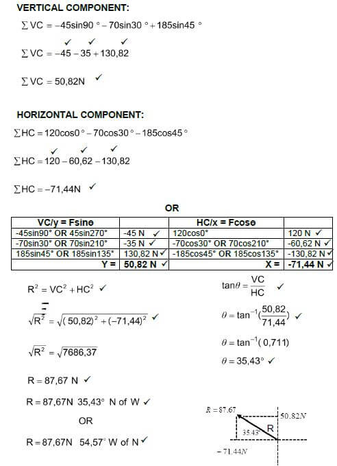
(15)
8.2 Moments: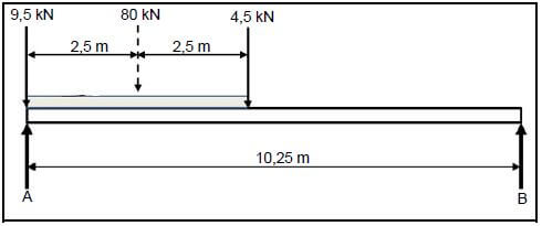
8.2.1 Point load for UDL:
- 16kN/m x 5m
80 kN (2)
8.2.2 Take moments about B:
- A x 10,25) = (4,5 x 5,25) + (80 x 7,75) + (9,5 x 10,25)
10,25A = 23,625 + 620 + 97,375
A = 741/10,25
A = 72,29 kN (3)
8.2.3 Take moments about A:
- B x 10,25) = (9,5 x 0) + (80 x 2,5) + (4,5 x 5)
10,25B = 0 + 200 + 22,5
B = 222,5/10,25
B = 21,71kN (3)
8.3.1 The stress in the material in MPa:
- σ = F/A
σ = 90 x 103
6,17 x 10⁻³
σ = 14586709,89 Pa
σ = 14,59 MPa (2)
8.3.2 The diameter of the mild steel shaft:
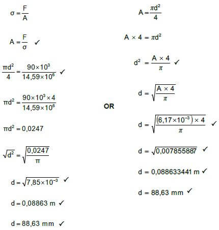
(5)
8.3.3 Original length: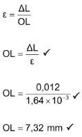
(3)
[33]
QUESTION 9: MAINTENANCE (SPECIFIC)
9.1 Preventative maintenance:
- Planned or scheduled maintenance.
- Condition-based maintenance. (2)
9.2 Preventative maintenance of gear drive systems:
- Checking and replenishment of lubrication levels.
- Ensuring that gears are properly secured to shafts.
- Cleaning and replacement oil filters.
- Reporting excessive noise, wear, vibration and overheating for expert attention.
(Any 3 x 1) (3)
9.3 Purpose of jockey pulley:
- The jockey pulley helps setting the tension on the system.
- To increase the angle of contact in an open belt drive.
(Any 1 x 1) (1)
9.4 Properties of materials:
9.4.1 Teflon:
- Water resistant.
- Resistant to grease.
- Resistant to heat.
- Resistant to corrosion.
- Can withstand high temperatures.
- Need no lubricants.
- Electrical insulator
- Thermoplastic /Easy to be reshaped / recycled.
(Any 2 x 1) (2)
9.4.2 Nylon:
- Tough.
- Hard-wearing.
- Cheap.
- Needs no or little maintenance.
- Can withstand high temperatures.
- Need no or little lubricants.
- Is light.
- Can absorb shock.
- Resistant to chemicals.
- Non-toxic.
- Thermoplastic /Easy to be reshaped.
- Has high load-bearing strength
(Any 2 x 1) (2)
9.4.3 Vesconite:
- Wear resistant.
- Low friction.
- Operate with little or no lubrication.
- Easy to machine.
- Load carry higher than white metal.
- Cost effective material.
- Gives long life span.
- Performs well, in unhygienic, dirty and un-lubricated environments.
- Low maintenance.
- Low or no water absorption
- High chemical resistance
- Versatile
- Can handle high temperatures
- Thermoplastic /Easy to be reshaped
(Any 2 x 1) (2)
9.5 Use of material:
9.5.1 Polyvinyl chloride (PVC): (Due to the large number of alternatives, marker discretion must be used - discuss with IM).
- Electrical cable isolation.
- Electrical pipes.
- Water pipes.
- Artificial leather.
- Cling wrap.
- Credit / bank / phone cards.
- Window frames.
- Fences.
- Furniture.
(Any 1 x 1) (1)
9.5.2 Glass fibre: (Due to the large number of alternatives, marker discretion must be used - discuss with IM).
- Boats.
- Motor vehicles bodies.
- Transparent roof sheeting.
- Petrol tanks.
- Swimming pools.
- Furniture.
- Fruit and salad bowls.
- Ornaments.
- Fishing equipment.
(Any 1 x 1) (1)
9.6 Difference between thermoplastic and thermo-hardened composites:
- Thermoplastic can be re-heated and reshaped again where a thermo- hardened plastic cannot be re-heated, to be softened, shaped and moulded again. (4)
[18]
QUESTION 10: JOINING METHODS (SPECIFIC)
10.1 Screw thread:
- Square thread
- Acme thread
- V-screw thread
- Trapezium thread / Buttress thread
(Any 3 x 1 ) (3)
10.2 Square Thread:
10.2.1 Pitch diameter:
- Pitch = Lead /Numberof starts
= 36/2
=18 mm ?
PD = OD - P/2
= 80 - 18/2
= 71 mm ? (4)
10.2.2 Helix angle of the thread:
- Tanθ = Lead
π x PD
Tanθ = 36
π x 71 ?
θ = tan-1(0,161396562)
= 9,17º (4)
10.2.3 Leading angle:
- Leading angle = 90° - (helix angle + clearance angle)
= 90° - (9,17° + 3°)
= 77,83° (2)
10.2.4 Following angle:
- Following angle = 90° + (helix angle - clearance)
= 90° + (9,17° - 3°)
= 96,17° (2)
10.3 Multiple screw threads:
- They provide more bearing surface than single start screw thread / does not strip easily.
- To provide faster linear movement.
- They are more efficient as they lose less power to friction compared to single start screw threads. (3)
[18]
QUESTION 11: SYSTEMS AND CONTROL (DRIVE SYSTEMS) (SPECIFIC)
11.1 Hydraulics:
11.1.1 The fluid pressure: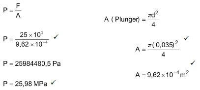
(4)
11.1.2 Force at ram: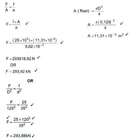
(5)
11.2 Functions hydraulic reservoir:
- A fluid storage tank.
- Promotes air separation from the fluid.
- Support for the pump and electric motor.
- Promotes heat dispersion.
- Acts as a base plate for mounting control equipment.
- Permits contaminants to settle at the bottom in order to be drained.
(Any 1 x 1) (1)
11.3 Efficiency of pneumatic systems:
- Pneumatic tools are environmentally friendly.
- Last long.
- It is robust (powerful / less force required)
- Easy to use.
- It is compact.
- Easy to maintain as there are so few working parts.
(Any 2 x 1) (2)
11.4 Applications for pneumatic systems: (Due to the large number of alternatives, marker discretion must be used - discuss with IM).
- Drills.
- Brake systems.
- Jackhammers
- Nail guns
- Missiles
- Doors
- Spray guns
- Air blow guns
- Air socket wrench
- Grinders
(Any 2 x 1) (2)
11.5 Belt drives:
11.5.1 Rotation frequency: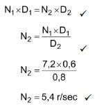
(3)
11.5.2 Power transmitted: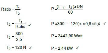
(4)
11.6 Gear drives:
11.6.1 Rotation frequency: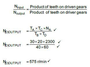
(4)
11.6.2 Gear ratio:
- Gear ratio = Product of teeth on driven gears/Product of teeth on driver gears
Gear ratio = 40 x 60
30 x 20
Gear ratio = 4 : 1
OR
- Speed ratio = NA
ND
= 2300
575
= 4:1 (3)
[28]
TOTAL: 200