MECHANICAL TECHNOLOGY(AUTOMOTIVE) GRADE 12 MEMORANDUM - NSC PAST PAPERS AND MEMOS NOVEMBER 2021
Share via Whatsapp Join our WhatsApp Group Join our Telegram GroupMARKING GUIDELINES
QUESTION 1: MULTIPLE-CHOICE QUESTIONS (GENERIC)
1.1 .B (1)
1.2 A (1)
1.3 D (1)
1.4 A / C (1)
1.5 A (1)
1.6 C (1) [6]
QUESTION 2: SAFETY (GENERIC)
2.1 First-aid applications to an open wound:
- Use surgical gloves.
- Do not remove anything that is stuck to the wound.
- Never use sticky plaster on the wound.
- Cover the wound with a clean, lint-free cloth.
- Avoid using any oily substances or lotions on wounds.
- If necessary, cool wounds with cold water.
- Apply pressure to prevent blood loss if necessary.
- Avoid contact with blood from patient.
- If the wound is on your arm, raise the arm above your head to stop the bleeding.
(Any 2 x 1) (2)
2.2 Surface grinder: (Already switched on)
- Never leave the grinder unattended.
- Switch off the machine when leaving.
- Don’t try to stop revolving emery wheel with your hand.
- Don’t adjust the machine while working.
- Don’t open any guard while the machine is on.
- Do not force the grinding wheel on to the work piece.
- Approach the work piece slowly and evenly.
- Don’t clean the machine while working.
- Do not put hands near the work piece when grinder is in motion.
- Don’t clean or adjust the machine while working.
- Check for oil on the floor while working (spilling of cutting fluid on floor while working)
- Check that the grinding wheel is running evenly.
(Any 2 x 1) (2)
2.3 Gauges calibrated:
- To ensure accurate readings.
- To prevent overloading.
(Any 1 x 1) (1)
2.4 Finger protectors’ hazards on power driven guillotines:
- The finger protector prevents the hazards of getting the fingers cut by the blades.
- To be crushed by the hold-downs. (2)
2.5 Welding or flame cutting operation safety:
- An operator has been instructed on how to use the equipment safely.
- A workplace is effectively partitioned off.
- An operator uses protective equipment.
- Ensure that all equipment is in safe working condition.
- Ensure that here are no flammable materials around the welding area.
- Weld area must be well ventilated.
- Fire extinguisher must be in close proximity.
(Any 2 x 1) (2)
2.6 Workshop layout:
- Product layout. (1)
[10]
QUESTION 3: MATERIALS (GENERIC)
3.1 File test:
3.1.1 Difficult (1)
3.1.2 Easy (1)
3.1.3 Difficult (1)
3.2 Heat treatment:
- A. – Grain growth.
- B. – Recrystallisation.
- C. – Recovery.
(3)
3.3 Bending test:
- Bend the test piece through a specific angle or around a mandrel or bar, having a defined radius, until a rupture in the metal occurs.
- Place the material in a vice and bend it then observe the ductility of the material.
(Any 1 x 3) (3)
3.4 Purpose of case hardening:
- Creates a hard surface with a tough core. (2)
3.5 Quenching media for hardening:
- Water
- Brine (saltwater)
- Oil
- Soluble oil and water
- Nitrogen air-infused air
(Any 3 x 1) (3)
[14]
QUESTION 4: MULTIPLE-CHOICE QUESTIONS (SPECIFIC)
4.1 C (1)
4.2 B (1)
4.3 C (1)
4.4 A (1)
4.5 B (1)
4.6 D (1)
4.7 B (1)
4.8 D (1)
4.9 A (1)
4.10 C (1)
4.11 A (1)
4.12 D (1)
4.13 D (1)
4.14 B (1)
[14]
QUESTION 5: TOOLS AND EQUIPMENT (SPECIFIC)
5.1 Compression test: (Please note that if one step is missing and others still follow the sequence, marks can still be allocated accordingly) 5.1.1 – 5.1.4
- Completely open the throttle valve. (1)
- Crank the engine until maximum pressure is reached (normally 4 to 10 revolutions)/needle stops moving. (1)
- Read the pressure that the piston created, off the gauge. (1)
- Move on to the next cylinders/Compare the readings of all the cylinders to the manufacturer’s specification’s readings/Compare readings with each other. (1)
5.2 Cylinder leakage tester:
5.2.1 Labelling:
- A - Leakage meter / gauge
- B - Control valve
- C - Flexible hose / pipe / tube
- D - Spark plug connector / adaptor (4)
5.2.2 Unit of measure:
- Percentage or % (1)
5.3 Exhaust gas analyser:
- Water trap
- Paper filter
- Condenser
(Any 2 x 1) (2)
5.4 Set up of the on-board diagnostics (OBD) scanner:
- Plug the on-board diagnostics (OBD) scanner into the connector.
- Turn on the ignition but do not start the car.
- Enter the vehicle information as required by the scanner.
- Select correct system to scan (diagnostics)
(Any 3 x 1) (3)
5.5 Wheel balancer:
5.5.1 Wheel balancer (1)
5.5.2 Function of the wheel balancer:
- To balance wheels / statically / dynamically. (1)
5.5.3 Safety feature:
- Wheel safety cover / guard / hood (1)
5.6 Wheel alignment angles:
- Caster
- Camber
- King pin inclination (KPI) / steering axis (3)
5.7 Wheel alignment precautions:
- Ensure the wheels are in a straight-ahead position
- Ensure the steering box is on its high spot.
- Centralise the steering wheel.
- Lock the steering wheel in place.
- Lock the brake pedal.
- Check tire and rim condition.
- Check tyre pressure and size.
- Calibrate / zero the equipment before it is fitted to the wheels.
(Any 3 x 1) (3)
[23]
QUESTION 6: ENGINES (SPECIFIC)
6.1 Crankshaft firing order:
- To overcome the twisting effect of the power stroke on the crankshaft.
- To reduce vibrations on the crankshaft.
- Increase the lifespan of the crankshaft.
- To improve engine cooling evenly throughout the engine.
(Any 3 x 1) (3)
6.2 Crankshaft dynamic imbalance:
- Fit balance mass pieces to the crank webs.
- Remove metal from the crank webs.
- Arrange the crank webs on opposite sides of the crank pins.
- Add a vibration damper.
(Any 2 x 1) (2)
6.3 Engine vibration:
- The varying quantity of torque / low compression produced on power strokes.
- The crankshaft alternately winding up and releasing as it rotates.
- The crankshaft also has its own natural frequency of vibration.
- The coinciding of different dynamic imbalances could produce excessive vibration called resonance.
- The torsional/twisting effect of the power strokes upon the crankshaft.
- The crankshaft is not statically balanced.
- The crankshaft is not dynamically balanced.
- The flywheel is not statically balanced.
- The flywheel is not dynamically balanced.
- The reciprocating mass is not balanced.
- Faulty vibration damper.
- Engine misfire.
- Incorrect air/fuel ratio.
- Improper tightened / loose engine components.
- Worn parts.
(Any 4 x 1)(4)
6.4 Power Impulses:
6.4.1 180° (1)
6.4.2 144° (1)
6.4.3 120° (1)
6.4.4 90° (1)
6.5 Roots supercharger:
6.5.1 Labels:
- A – Casing / housing
- B – Air inlet / fill side
- C – Rotor (3)
6.5.2 Operation of the Roots supercharger:
- The engine drives the rotors by means of gears, belt or a chain.
- Two symmetrical rotors spin.
- Trapped air, between the rotors and casing, is pushed from the inlet side to the discharge side.
- Large quantities of air move into the intake manifold.
- This creates increased pressure in the cylinder. (5)
6.6 Variable geometry turbocharger:
6.6.1 Function of intercooler:
- Intercooler is used to cool air that has been compressed by a turbocharger
- It reduces the volume and increases the density of the air.
- Improving volumetric efficiency.
(Any 1 x 2) (2)
6.6.2 Function of vanes:
- Vanes alter the air flow path of the exhaust gases to optimize the turbine speed. (2)
6.7 Advantages of a supercharger over a turbocharger:
- Does not suffer lag.
- It is more efficient at lower r/min.
- Simpler installation.
- Cheaper to service and maintain.
- Does not always need an intercooler.
- No special lubrication required.
(Any 3 x 1) (3)
[28]
QUESTION 7: FORCES (SPECIFIC)
7.1 Definitions:
7.1.1 Brake power:
- Brake power is the useable power / actual power / output power developed at the flywheel or at the drive wheels. (2)
7.1.2 Torque:
- Torque is the twisting effort / force on a shaft or wheel.
- Torque is the twisting effort / force measured over the applied radius.
(Any 1 x 2) (2)
7.2 Indicated power diagram:
- Compression stroke - pressure rise / increase.
- Power stroke - pressure drop / decrease. (2)
7.3 Calculations:
7.3.1 V1 - Clearance volume (1)
7.3.2 V2 - Swept volume (1)
7.3.3 Cylinder volume:
330 ml = 330 cm3
Total cylinder volume = V1 + V2
= 39 + 330
= 369 cm3 (3)
7.3.4 Bore diameter in mm: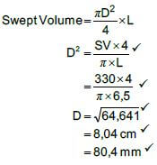
(5)
7.3.5 Compression ratio:
- CR = Total cylinder volume/Clearancevolume
= 369/39
= 9.46
= 9,5 : 1 (2)
7.4 Methods to lower the compression ratio:
- Fit thicker gasket between cylinder block and cylinder head.
- Fit pistons with suitable lower crowns.
- Fit crankshaft with shorter stroke.
- Fit suitable shorter connecting rods.
- Re-sleeve to a smaller bore size.
- Fit a shim between the cylinder head and engine block.
(Any 2 x 1) (2)
7.5 Calculations:
7.5.1 Torque:
- BP = 2πNT/60
T = BP/2π N
= 48 000x 60
2 x π x 6 500
= 70,52 N.m (4)
7.5.2 Indicated power in kW:
- Lx A = Volume
= 580,7 cm3
= 580,7x10⁻⁶ m3
N = 6 500/60x1
= 108,33 power stroke/sec - IP = PLANn
= 450 x103 x 580,7x10-6 x 108,33 x 2
= 56 618,25 W
= 56,62 kW (6)
7.5.3 Mechanical efficiency:
- Mechanical Efficiency (η ) = BP/IP x100
= 48/56,62 x 100
= 84,78 % (2)
[32]
QUESTION 8: MAINTENANCE (SPECIFIC)
8.1 Low CO2 exhaust gas reading:
8.1.1 Possible causes:
- Too rich air/fuel mixture.
- Ignition misfire / Blown cylinder head or block.
- Dirty or restricted air filter.
- Improper operation of the fuel delivery system / Excessive fuel delivery pressure.
- Faulty thermostat or coolant sensor.
- Faulty PCV valve system.
- Catalytic converter not working.
- Exhaust system leaks
(Any 2 x 1) (2)
8.1.2 Corrective measures:
Note: The answer for 8.1.2 must correspond with the causes mentioned in 8.1.1.
- Reset fuel mixture
- Correct cause of misfire / Replace cylinder head or block.
- Replace air filter.
- Correct fuel delivery system pressure.
- Repair or replace thermostat or coolant sensor.
- Repair PCV system.
- Repair or replace catalytic converter.
- Repair exhaust system.
(Any 2 x 1) (2)
8.2 Indicate lean air/fuel mixture:
- High oxygen (O2).
- High carbon dioxide (CO2).
- High nitrogen oxide (NOx).
(Any 2 x 1) (2)
8.3 Cylinder leakage test:
8.3.1 Hissing sound at the exhaust pipe:
Cause | Corrective measure |
· Leaking exhaust valve |
|
| |
(Any 1 x 1) |
(2)
8.3.2 Bubbles in the radiator water:
Cause | Corrective measure | (2) |
|
| |
(Any 1 x 1) | (Any 1 x 1) |
(2)
8.4 Engine temperature:
- To allow the expansion of the components to obtain accurate readings. (2)
8.5 Fuel pressure test:
8.5.1 Replace fuel filter (1)
8.5.2
- Cracked fuel line
- Restricted / blocked fuel line
(Any 1 x 1) (1)
8.5.3
- Clean the strainer
- Replace the strainer
(Any 1 x 1) (1)
8.5.4
- Incorrect / Low voltage to the fuel pump
- Pump speed is slow
- Pump is not operational
(Any 1 x 1) (1)
8.6 Oil pressure test:
- Oil pressure when engine is idling.
- Oil pressure when engine is cold.
- Oil pressure when engine is hot.
- Oil pressure when engine is at high revolutions.
(Any 3 x 1) (3)
8.7 Radiator cap pressure test:
- Obtain the radiator cap's opening pressure specifications (stamped on the cap).
- Install the cap onto the adapter of the cooling system pressure tester.
- Pump up the tester while watching the pressure gauge.
- Note the reading when the pressure is released. (4)
[23]
QUESTION 9: SYSTEMS AND CONTROL (AUTOMATIC GEARBOX) (SPECIFIC)
9.1 Torque converters:
9.1.1 Torque converter labels:
- Turbine
- Casing / housing
- Pump / Impeller
- Turbine shaft / output shaft
- Stator (5)
9.1.2 Functions of torque converters:
- Multiplies engine torque automatically according to road and engine speeds.
- Transfers drive from the engine to the transmission.
- Acts as a flywheel to keep the engine turning during the idle strokes.
- Slips during initial acceleration and while stopping to prevent stalling.
- Dampens torsional vibrations of the engine.
- Wheel spin is greatly reduced.
- Drive the transmission oil pump.
- Contributes toward smooth gear changing.
(Any 3 x 1) (3)
9.1.3 Maximum torque multiplication:
- When there is the largest speed difference between the impeller and turbine.
- Maximum torque multiplication occurs at rest, as the vehicle just starts to move.
(Any 1 x 2) (2)
9.2 Epicyclic gear train: (forward overdrive)
- The sun gear is locked with the planet carrier as driving member and the annulus as driven component.
- The annulus is locked with the planet carrier as driving member and the sun gear is the driven component.
(Any 1 x 3) (3)
9.3 Gearshift lever positions:
9.3.1 P – park (1)
9.3.2 R – reverse (1)
9.3.3 D – drive (1)
9.4
- P
- N (2)
[18]
QUESTION 10: SYSTEMS AND CONTROL (AXLES, STEERING GEOMETRY AND ELECTRONICS) (SPECIFIC)
10.1 Reasons for wheel alignment:
To achieve:
- desirable steering / Drive with least resistance.
- easier steering control.
- better tracking.
- minimal vibrations.
- even road-holding.
- increase tyre life.
- Checking of the camber angle.
- Checking of the kingpin inclination.
- Checking of the castor angle.
- Checking of the toe-out / toe-in.
- Less fuel consumption.
(Any 3 x 1) (3)
10.2 Camber:
10.2.1 Camber wear causes:
- Suspension misalignment.
- A bent strut.
- Dislocated strut tower.
- A weak or broken spring.
- A bent stub axle.
- Collapsed or damaged control arm bushings.
- Worn upper strut bearing.
- Bent control arms.
- Improper wheel alignment setting.
- Damaged / worn ball joints.
(Any 4 x 1) (4)
10.2.2 Positive camber angle:
- Positive camber angle refers to the outward tilt of the top of the wheel. (2)
10.2.3 Camber adjustment:
- Camber is adjusted by means of a cam / wedge bolts or wedge plates (shims) on the suspension. (2)
10.3 Toe-in:
(3)
10.4 Effects of wheel imbalances:
- Wheel shimmy (wobble).
- Wheel bounce (hop).
- Uneven tyre wear.
- Premature wheel bearing failure.
- Rapid tyre wear.
- Increased friction between road surface and the tyre.
(Any 2 x 1) (2)
10.5 Types of injectors:
- Solenoid injector
- Piezo injector (2)
10.6 Purpose of the diesel particulate filter:
- It is a filter that converts particulate matter or soot into ash. (2)
10.7 The headway sensor:
- The headway sensor detects an obstruction ahead of a vehicle.
- The headway sensor will send a signal to the ECU. (2)
10.8 The alternator:
10.8.1 Component:
- Stator (1)
10.8.2 Stator function:
- It provides a coil into which a voltage is induced,
- Converts the rotating magnetic field to electric current.
(Any 1 x 2) (2)
10.8.3 Stator windings: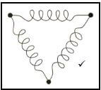
- Delta connected stator windings (2)
10.8.4 Stator windings: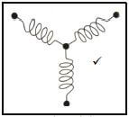
- Star or Y connected stator windings (2)
10.9 Advantages of an electric fuel pump:
- Immediate/quicker supply of fuel when the ignition switch is turned on.
- Low sound during operation.
- Less discharge pulsation of fuel.
- Compact and light design.
- Able to prevent internal fuel leaks and vapour lock.
- Can be fitted within any location on the fuel line.
(Any 3 x 1) (3)
[32]
TOTAL: 200