ELECTRICAL TECHNOLOGY(POWER SYSTEMS) GRADE 12 MEMORANDUM - NSC PAST PAPERS AND MEMOS NOVEMBER 2021
Share via Whatsapp Join our WhatsApp Group Join our Telegram GroupINSTRUCTIONS TO THE MARKERS
- All questions with multiple answers imply that any relevant, acceptable answer should be considered.
- Calculations:
2.1 All calculations must show the formulae.
2.2 Substitution of values must be done correctly.
2.3 All answers MUST contain the correct unit to be considered.
2.4 Alternative methods must be considered, provided that the correct answer is obtained.
2.5 Where an incorrect answer could be carried over to the next step, the first answer will be deemed incorrect. However, should the incorrect answer be carried over correctly, the marker has to re- calculate the values, using the incorrect answer from the first calculation. If correctly used, the candidate should receive the full marks for subsequent calculations. - These marking guidelines are only a guide with model answers. Alternative interpretations must be considered and marked on merit. However, this principle should be applied consistently throughout the marking session at ALL marking centres.
MARKING GUIDELINES
QUESTION 1: MULTIPLE-CHOICE QUESTION
1.1 C (1)
1.2 B (1)
1.3 A (1)
1.4 D (1)
1.5 A (1)
1.6 C (1)
1.7 B (1)
1.8 D (1)
1.9 A (1)
1.10 D (1)
1.11 B (1)
1.12 C (1)
1.13 D (1)
1.14 A (1)
1.15 A (1)
[15]
QUESTION 2: OCCUPATIONAL HEALTH AND SAFETY
2.1
- To identify and communicate potential hazards
- To identify potential major incidents at the workplace to the employer.
OR - To review the effectiveness of health and safety measures.
- To investigate complaints by employees relating to health and safety at work. (2)
2.2
- Your right to earn a living wage.
- Your right to work for reasonable hours.
- Your right to belong to a trade union. (2)
2.3 An unsafe act is an action committed by a person which may lead to an accident or unsafe condition and/or loss.
An unsafe condition is a work related environmental condition which may lead to or contribute to an accident and/or loss. (2)
2.4
- High impact, low probability.
- High impact, high probability.
- Low impact, low probability.
- Low impact, high probability.
- Qualitative risk analysis.
- Quantitative risk analysis. (1)
2.5 'Danger' means anything that may cause injury to a person or damage to property. (2)
2.6
- Use an apron to protect your clothes from staining.
- Use protective glasses to protect your eyes.
- Use latex gloves to prevent skin irritation.
- Use a mask to reduce the risk of breathing fumes. (1)
[10]
QUESTION 3: RLC CIRCUITS
3.1 Capacitive reactance is the opposition of the capacitor to alternating current in an AC circuit. (2)
3.2 There is a 90° phase shift between VL and IL where IL lags VL by 90°. (1)
3.3
3.3.1
? = X?
2 × ? × ƒ
= 150
2 × ? × 60
= 0,40 ?
= 400 ?? (3)
3.3.2 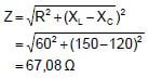
(3)
3.3.3
??? ? = ?
?
= 60
67,08
= 0,89 (3)
3.3.4
- R = Z
- Phase angle = 0°
- VL = VC
- XL = XC
- I is maximum (3)
3.4
3.4.1 800 Hz (1)
3.4.2 When the frequency increases from 200 Hz to 1600 Hz, the inductive reactance increases and the capacitive reactance decreases. (2)
3.4.3 ?? = ?? × X?
= 0,66 × 10−6 × 750
= 495 µ? (3)
3.4.4
Xc = 1
2?fc
C = 1
2?fXc
= 1
2?(600)(1333)
= 198,99 x 10⁻⁹ F
= 198,99 nF (3)
3.5
3.5.1 At resonance Z = R = 20 Ω
I = VT
Z
= 220
20
= 11 A (3)
3.5.2
VL = I x XL
= 11 x 50
= 550V (3)
3.5.3
Q = XL
R
= 50/20
= 2,5
NOTE: XC over R is also accepted
Q = VL/VT
= 550/220
= 2,5 (3)
3.5.4 The phase angle would be zero because XL is equal to XC and thus VL = VC and out of phase with each other this would cancel each other, resulting in a power factor of 1.
R=Z
The circuit is at resonance (2)
[35]
QUESTION 4: THREE-PHASE AC GENERATION
4.1
4.1.1
- A - Generation
- B - Transmission
- C - Distribution (3)
4.1.2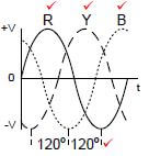
NOTE: The sequence of R,Y,B (VL1, VL2, VL3) must be correct to be awarded full marks. The sequence given in the textbook as B,R,Y will be accepted as correct (4)
4.1.3 The voltage from the Generation process must be stepped up to reduce the current in the transmission lines and therefore reducing the copper losses (I2R losses) in the transmission lines. (2)
4.1.4 Star, because the end user needs to power both three-phase and single-phase equipment which is only possible with a star connection. (2)
4.2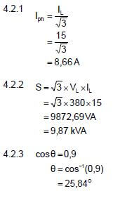
4.2.4
Q = √3 x VL x IL x sinθ
= √3 x 380 x15 x sin(25,84)
= 4303,11VA R
= 4,3 kVA R (3)
4.3
- Less current drawn from the supply.
- Reduced monthly electricity bill.
- Reduced heat generated by equipment that will then last longer.
- Less maintenance of equipment. (2)
4.4
4.4.1 The meter shows a lagging power factor. (1)
4.4.2 The connected load is predominantly inductive. (1)
4.4.3
- By connecting capacitors in parallel with the load.
- By using synchronous motors. By using phase advancers. (1)
4.5
4.5.1
PT = P1 + P2
= 250 + 460
= 710 W (3)
4.5.2
- The phase angle.
- Power factor. (2)
4.5.3
- The meters can easily be connected to the lines.
- The same connection is used for star or delta connected loads.
- It is a more economical method of load measurement. (2)
[35]
QUESTION 5: THREE-PHASE TRANSFORMERS
5.1
5.1.1
- A - Oil conservator (Oil tank)
- B - Bushings (Isolators) (2)
5.1.2
- Oil Natural Air Forced
- Oil Forced Air Forced
- Oil Natural Air Natural (when the fan is off)
- Oil Forced Water Forced (2)
5.1.3
- Inverse definite time relay Instantaneous overcurrent relay Balanced earth fault relay Buchholz relay
- Restricted earth fault relay Standby earth fault relay
- Directional overcurrent relay (3)
5.1.4
- In a step down transformer the secondary has less windings than the primary. The primary winding is connected to an alternating voltage.
- This sets up an alternating emf in the primary windings and alternating current flows.
- This alternating current creates an alternating magnetic field which links with the secondary winding through the magnetic core. (Faraday’s law)
- The alternating magnetic field cuts the secondary winding creating a smaller alternating emf in it.
- Due to the reduced windings, the secondary voltage will be lower than the primary voltage in accordance with the turns ratio and voltage per winding in the primary and secondary windings of the transformer. (5)
5.2
- The windings are enclosed.
- The axis of the shell type can be horizontal or vertical.
- The core hides the major part of the windings. The core has five limbs.
- The coils are wound around the central section of the core. (2)
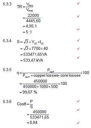
5.3
5.3.1 Delta star step-down transformer (1)
5.3.2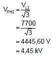
(3)
[30]
QUESTION 6: THREE-PHASE MOTORS AND STARTERS
6.1
6.1.1
- A – Terminal Box (Wiring Cover)
- B – Motor frame (Enclosure/Housing/Stator)
- C – Rotor (3)
6.1.2
- Each of the stator windings is connected to a line of the three phase supply in the terminal box.
- Each coil creates a magnetic field at alternate intervals (120º).
- The coils are spaced around the stator in such a way that it creates the impression of a rotating magnetic field to the rotor.
OR - When a three-phase supply is connected to a three-phase motor stator a rotary magnetic field is established.
- This is achieved by the three phases reaching maximum strength 120o out of phase with each other. (3)
6.1.3
- Cranes.
- Conveyor belt systems.
- Lathes.
- Drill presses. Bench grinders. (2)
6.1.4
- Number of pole pairs.
- Frequency of the supply. (2)
6.2
6.2.1 This motor is connected in delta. (1)
6.2.2 Swop any TWO of the supply lines. (1)
6.2.3
- Disconnect the supply lines from the motor.
- Remove the internal connecting plates. (2)
6.3 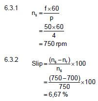
6.3.3
P = √3 x VL x IL x cosθ x η
= 3 x 380x 6 x 0,85 x 90/100
= 3021,04 W
= 3,02 kW (3)
6.4
6.4.1 MC1N/O1 (1)
6.4.2 MC1N/O2 is a hold-out contact ensuring that MC2 can only be energised if MC1 is energised. (2)
6.4.3
- If either motor 1 or motor 2 is overloaded the whole circuit will be isolated.
OR - If any one of the two overload relays are activated by either O/L1 or O/L2 it will cut the power to the whole circuit. (2)
6.4.4
- When START 1 is pressed MC1 will energise.
- This will immediately close contacts MC1N/O1 (hold-in) and MC1N/O2 (hold-out) and START 1 button can be released.
- Only after MC1N/O2 is closed you can press START 2.
- When START 2 is pressed, MC2 will energise closing contact MC2N/O1 so that the start button can be released.
- When the STOP button is pressed, MC1 will de-energise opening contact MC1N/O2 and de-energising MC2. (5)
6.4.5 If contact MC2N/O1 is faulty and permanently closed, contactor MC2 will immediately energise when MC1 is energised, without pressing START button 2. (2)
[35]
QUESTION 7: PROGRAMMABLE LOGIC CONTROLLERS (PLCs)
7.1
7.1.1
- Input module
- Output module
- Power supply (2)
7.1.2
- The CPU controls the PLC.
- Performs all calculations.
- It runs the PLC program.
- It processes all the input and output signals. (3)
7.1.3
- Transistor
- Relay (1)
7.2 'Scan time' is the time the PLC takes to complete one scan cycle. (2)
7.3 Software is the machine language installed on a computer or written into a PLC’s control program that instructs it to interact with its input and output
hardware. (3)
7.4
7.4.1 A sensor is a device that detects a physical condition and changes its electrical characteristics, such as resistance. (2)
7.4.2
- Light sensor.
- Level sensor.
- Proximity sensor.
- Temperature sensor. (3)
7.4.3
- The overload sensor will continuously (analogous) change its characteristic resistance as the load on it is altered or changed. (Not in a stepped digital format)
OR - When connected to the analogue input on a PLC, parameters can be determined within which the PLC will execute. (3)
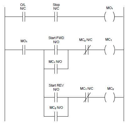
7.5 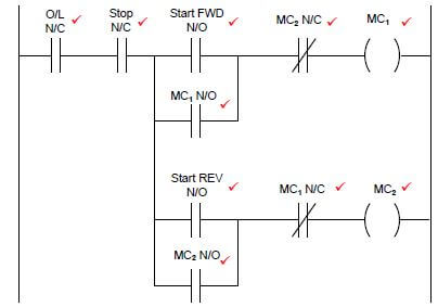
NOTE: O/L and Stop must both be in the same condition (either open or closed) (10)
OR
7.6
7.6.1 DC-to-AC Inverter. (1)
7.6.2
- Insulated Gate Bipolar Transistor (IGBT)
- Metal Oxide Semi-Conductor Field Effect Transistor (MOSFET) (1)
7.6.3
- Improves energy usage.
- Reduces motor wear.
- Achieves variable motor speed control. (2)
7.6.4 Vector drives use a mathematical model of the drive-in software. By measuring the current vectors in relation to the applied voltage. They are able to maintain a constant field at all frequencies below the line frequency. (3)
7.7 When the momentum of a load drives the motor, the motor changes into a generator converting the mechanical energy into electrical energy and in
the process slowing the acceleration of the load. (3)
7.8 Braking Resistor. (1)
[40]
TOTAL: 200