ELECTRICAL TECHNOLOGY(POWER SYSTEMS) GRADE 12 QUESTIONS - NSC PAST PAPERS AND MEMOS NOVEMBER 2021
Share via Whatsapp Join our WhatsApp Group Join our Telegram GroupINSTRUCTIONS AND INFORMATION
- This question paper consists of SEVEN questions.
- Answer ALL the questions.
- Sketches and diagrams must be large, neat and FULLY LABELLED.
- Show ALL calculations and round off answers correctly to TWO decimal places.
- Number the answers correctly according to the numbering system used in this question paper
- You may use a non-programmable calculator.
- Calculations must include:
7.1 Formulae and manipulations where needed
7.2 Correct replacement of values
7.3 Correct answer and relevant units where applicable - A formula sheet is attached at the end of this question paper.
- Write neatly and legibly.
QUESTIONS
QUESTION 1: MULTIPLE-CHOICE QUESTIONS
Various options are provided as possible answers to the following questions. Choose the answer and write only the letter (A–D) next to the question numbers (1.1 to 1.15) in the ANSWER BOOK, e.g. 1.16 E.
1.1 Choose the correct example of an unsafe condition that is likely to cause damage to property or an injury:
- Running in the workshop
- Spilling liquid or oil without cleaning it up
- Faulty tools or equipment
- Overloading electrical outlets when connecting many appliances (1)
1.2 An RLC series circuit is predominantly inductive when …
- XC > XL
- XL > XC
- XL = XC
- VC > VL (1)
1.3 The phase angle of a predominantly capacitive RLC series circuit is …
- leading.
- lagging.
- in phase.
- zero. (1)
1.4 The … of a resonant circuit is the measure of how well it responds to a range of frequencies.
- conductance
- dissipation factor
- resonant frequency
- selectivity (1)
1.5 The standard international phase sequence for a three-phase system is …
- red, yellow, blue.
- red, blue, yellow.
- blue, yellow, red.
- yellow, blue, red. (1)
1.6 The phase angle between any two phases of a balanced three-phase system is …
- 150 degrees.
- 180 degrees.
- 120 degrees.
- 90 degrees. (1)
1.7 A measuring instrument used to measure electrical energy is a …
- wattmeter.
- kWh meter.
- power factor meter.
- voltmeter. (1)
1.8 A step-up transformer is used to …
- increase the power.
- decrease the power.
- increase the current.
- increase the voltage. (1)
1.9 In three-phase transformers, the transfer of electrical energy from the primary winding to the secondary winding takes place by means of …
- mutual induction.
- self-induction.
- electrical connection.
- centrifugal force. (1)
1.10 Which ONE of the following relates to a mechanical inspection of a three-phase motor?
- Insulation-resistance test between the windings and earth
- Insulation-resistance test between windings
- Continuity test of the stator windings
- Stator must be checked for cracks (1)
1.11 The function of an overload relay in a motor starter control circuit is to …
- switch on the motor.
- deactivate the control circuit and to isolate the power circuit when excessive current flows through the motor.
- prevent the circuit from automatically restarting after a power failure.
- act as a hold-out contact. (1)
1.12 The speed of rotation of the magnetic field in the stator windings is called … speed.
- rotor
- slip
- synchronous
- efficiency (1)
1.13 The chronological order of operation for the scan cycle of a PLC is …
- scan inputs, update outputs, process inputs.
- update outputs, scan inputs, process inputs.
- process inputs, scan inputs, update outputs.
- scan inputs, process inputs, update outputs. (1)
1.14 A semiconductor device that uses light to connect an electrical signal between two electrically isolated circuits is called a/an …
- opto-coupler.
- relay.
- transformer.
- inductive proximity sensor. (1)
1.15 The purpose of the rectifier stage of a variable speed drive is to …
- convert AC to DC.
- smooth out ripple voltage.
- change DC to AC.
- store the electric charge. (1)
[15]
QUESTION 2: OCCUPATIONAL HEALTH AND SAFETY
2.1 State TWO functions of a health and safety representative. (2)
2.2 Give TWO examples of human rights in the workplace. (2)
2.3 Differentiate between an unsafe act and an unsafe condition. (2)
2.4 Risk analysis can be divided into different categories. Name ONE category. (1)
2.5 Define danger with reference to the Occupational Health and Safety Act, 1993 (Act 85 of 1993). (2)
2.6 Name ONE personal protective item you would use when etching a printed circuit board (PCB). (1)
[10]
QUESTION 3: RLC CIRCUITS
3.1 Define capacitive reactance with reference to RLC circuits. (2)
3.2 State the phase relationship between the current and voltage in a pure inductive AC circuit. (1)
3.3 Refer to FIGURE 3.3 below and answer the questions that follow.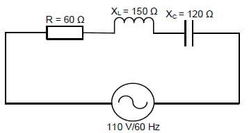
FIGURE 3.3: RLC SERIES CIRCUIT
Given:
R = 60 Ω
XC = 1 2 0 Ω
XL = 150 Ω
VT = 110 V
f = 60 Hz
3.3.1 Calculate the inductance of the inductor. (3)
3.3.2 Calculate the impedance of the circuit. (3)
3.3.3 Calculate the power factor. (3)
3.3.4 State THREE conditions that will occur if the power factor is at unity in a RLC series circuit. (3)
3.4 Refer to FIGURE 3.4 A and FIGURE 3.4 B below to answer the questions that follow.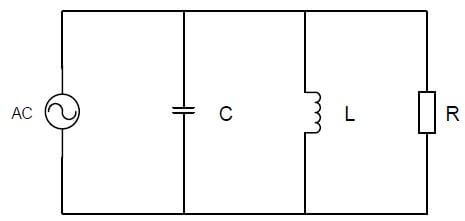
FIGURE 3.4 A: PARALLEL RESONANT CIRCUIT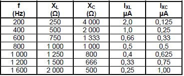
FIGURE 3.4 B: DATA OF THE RLC PARALLEL CIRCUIT
3.4.1 Determine the resonant frequency in FIGURE 3.4 B. (1)
3.4.2 Compare the values of the inductive reactance and capacitive reactance when the frequency increases from 200 Hz to 1 600 Hz. (2)
3.4.3 Calculate the voltage drop across the inductor when the frequency is 600 Hz. (3)
3.4.4 Calculate the value of the capacitor using the reactance value at 600 Hz. (3)
3.5 Refer to FIGURE 3.5 below and answer the questions that follow.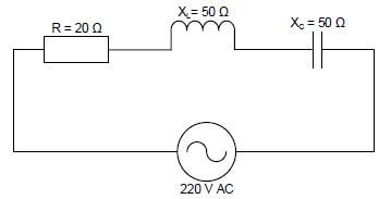
FIGURE 3.5: RLC SERIES CIRCUIT
3.5.1 Calculate the total current flow through the circuit. (3)
3.5.2 Calculate the voltage drop across the inductor. (3)
3.5.3 Calculate the Q-factor of the circuit. (3)
3.5.4 Explain why the phase angle of the circuit in FIGURE 3.5 would be zero. (2)
[35]
QUESTION 4: THREE-PHASE AC GENERATION
4.1 FIGURE 4.1 below is a block diagram of the national grid. Answer the questions that follow.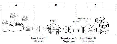
FIGURE 4.1: NATIONAL GRID
4.1.1 Name the processes at A, B and C. (3)
4.1.2 Draw the voltage waveforms generated at A. (4)
4.1.3 Explain why Transformer 1 is a step-up transformer. (2)
4.1.4 Determine the type of connection used on the secondary windings of Transformer 3 and motivate your answer. (2)
4.2 A delta-connected three-phase system draws a line current of 15 A and a line voltage of 380 V. It operates at a power factor of 0,9 lagging.
Answer the questions that follow.
Given:
IL = 15 A
VL = 380 V
cos θ = 0,9
Calculate the:
4.2.1 Phase current (3)
4.2.2 Apparent power (3)
4.2.3 Phase angle (3)
4.2.4 Reactive power (3)
4.3 State TWO advantages of power factor correction to the consumer. (2)
4.4 FIGURE 4.4 below shows an analogue power factor meter. Answer the questions that follow.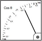
FIGURE 4.4: POWER FACTOR METER
4.4.1 Does the reading show a leading or lagging power factor? (1)
4.4.2 State the cause of this type of reading. (1)
4.4.3 State how the meter reading could be brought closer to unity. (1)
4.5 Refer to FIGURE 4.5 below and answer the questions that follow.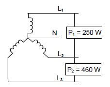
FIGURE 4.5: THREE-PHASE LOAD
4.5.1 Calculate the total power of the load. (3)
4.5.2 State TWO quantities, other than power, that can be determined by using the two-wattmeter method. (2)
4.5.3 Explain why the two-wattmeter method is preferred over the three-wattmeter method. (2)
[35]
QUESTION 5: THREE-PHASE TRANSFORMERS
5.1 FIGURE 5.1 below shows a three-phase transformer. Answer the questions that follow.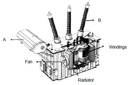
FIGURE 5.1: THREE-PHASE TRANSFORMER
5.1.1 Name parts A and B. (2)
5.1.2 Name TWO possible cooling methods of this transformer. (2)
5.1.3 List THREE protection devices used in three-phase transformers. (3)
5.1.4 Describe the operation of a step-down transformer. (5)
5.2 Name TWO physical characteristics of a three-phase shell-type transformer. (2)
5.3 FIGURE 5.3 below shows a three-phase transformer. Answer the questions that follow.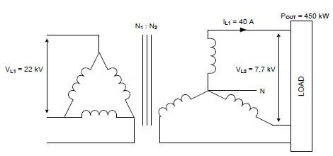
FIGURE 5.3: THREE-PHASE TRANSFORMER
Given:
VL1 = 22 kV
VL2 = 7,7 kV
IL1 = 40 A
POUT = 450 kW
5.3.1 Identify the configuration of the three-phase transformer in FIGURE 5.3. (1)
Calculate the:
5.3.2 Secondary phase voltage (3)
5.3.3 Transformer ratio (3)
5.3.4 Apparent power (3)
5.3.5 Efficiency if the copper losses are 1 kW and core losses are 500 W (3)
5.3.6 Power factor (3)
[30]
QUESTION 6: THREE-PHASE MOTORS AND STARTERS
6.1 Refer to FIGURE 6.1 below and answer the questions that follow. 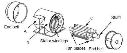
FIGURE 6.1: EXPLODED VIEW OF A THREE-PHASE MOTOR
6.1.1 Name parts A, B and C. (3)
6.1.2 Explain how a rotating magnetic field is created in the stator windings. (3)
6.1.3 State TWO applications of squirrel-cage induction motors. (2)
6.1.4 State TWO contributing factors that determine the speed of rotation in a three-phase induction motor. (2)
6.2 Refer to FIGURE 6.2 below and answer the questions that follow.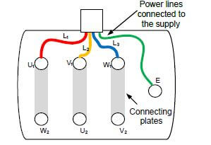
FIGURE 6.2: THREE-PHASE MOTOR CONNECTION
6.2.1 Is this motor connected in star or in delta? (1)
6.2.2 State how the direction of rotation of this motor can be reversed. (1)
6.2.3 Name TWO important procedures to follow before testing the insulation resistance of the motor in FIGURE 6.2. (2)
6.3 A star-connected three-phase motor with four pole pairs per phase draws a line current of 6 A when connected to a 380 V/50 Hz supply. The power factor
is 0,85 and the efficiency is 90%.
Given:
p = 4
IL = 6 A
VL = 380 V
f = 50 Hz
cos θ = 0,85
η = 90%
Calculate the:
6.3.1 Synchronous speed (3)
6.3.2 Percentage slip if the rotor speed is 700 r/min (3)
6.3.3 Output power (3)
6.4 Refer to FIGURE 6.4 below and answer the questions that follow.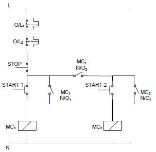
FIGURE 6.4: MANUAL SEQUENCE STARTER
6.4.1 Name the component that prevents MC1 from automatically energising when the power is restored after a power failure. (1)
6.4.2 State the function of MC1 N/O2. (2)
6.4.3 Explain the purpose of wiring O/L1 and O/L2 in series with the supply. (2)
6.4.4 Explain the operation of the circuit. (5)
6.4.5 Explain how the circuit operation will be affected if contact MC2 N/O1 is faulty and permanently closed. (2)
[35]
QUESTION 7: PROGRAMMABLE LOGIC CONTROLLERS (PLCs)
7.1 Refer to the hardware of a PLC and answer the questions that follow.
7.1.1 Name TWO types of hardware modules used in a PLC, other than the CPU. (2)
7.1.2 State THREE functions of the central processing unit (CPU). (3)
7.1.3 Name the component used to switch the load connected to a PLC. (1)
7.2 Explain the term scan time with reference to the scan cycle of the PLC. (2)
7.3 Explain the term software with reference to the PLC. (3)
7.4 Refer to sensors as input devices of a PLC and answer the questions that follow.
7.4.1 Define the term sensor. (2)
7.4.2 List THREE types of sensors other than the overload sensor.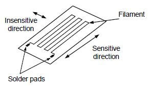
FIGURE 7.4.3: OVERLOAD SENSOR (3)
7.4.3 Explain why the overload sensor in FIGURE 7.4.3 is connected to an analogue input on a PLC. (3)
7.5 FIGURE 7.5 below shows a control circuit of a forward-reverse starter.
Draw the PLC ladder logic program that will execute the same function in a PLC system.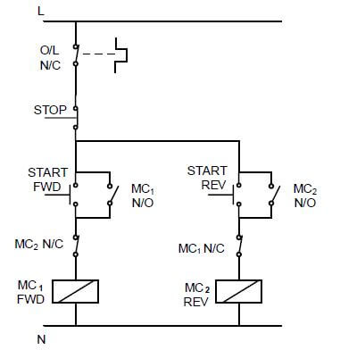
FIGURE 7.5: CONTROL CIRCUIT OF A FORWARD-REVERSE STARTER (10)
7.6 FIGURE 7.6 below shows the different stages in a variable speed drive. Answer the questions that follow.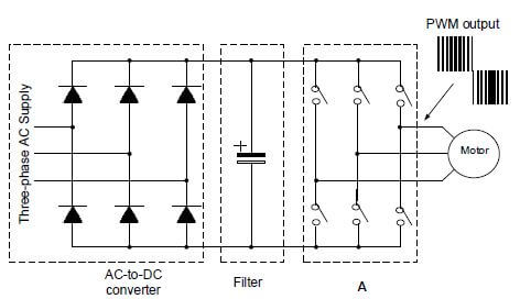
FIGURE 7.6 VARIABLE SPEED DRIVE STAGES
7.6.1 Identify stage A. (1)
7.6.2 Name a semiconductor component that could replace the switches used at A. (1)
7.6.3 State TWO advantages of using variable speed drives. (2)
7.6.4 Describe vector drives as a method of speed control. (3)
7.7 Explain the process of regenerative braking in a VSD system when the momentum of a load starts to drive a motor. (3)
7.8 Name the component used to dissipate the excessive energy during the process of regenerative braking. (1)
[40]
TOTAL: 200
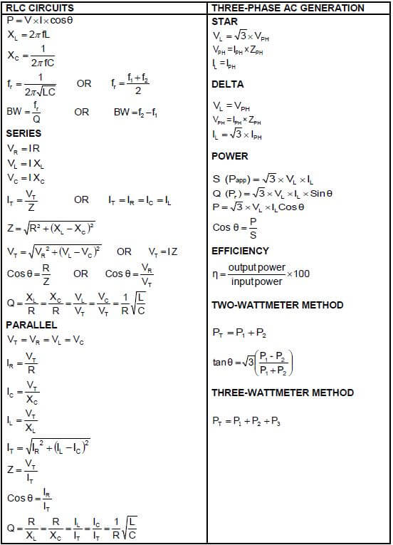
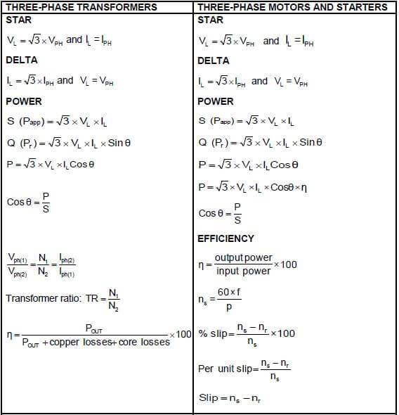
FORMULA SHEET