CIVIL TECHNOLOGY(CONSTRUCTION) GRADE 12 MEMORANDUM - NSC PAST PAPERS AND MEMOS NOVEMBER 2021
Share via Whatsapp Join our WhatsApp Group Join our Telegram GroupINSTRUCTIONS FOR THE MARKERS
- Markers should:
- Familiarise themselves with the question and answer before evaluating the responses of candidates.
- Always interpret the responses of the candidates within the context of the question.
- Consider any relevant and acceptable answer during pre-marking, but should strictly adhere to the answers after finalisation of the marking guidelines.
- There are two approaches to answering questions, these are (1) to describe and (2) to explain.
- If a candidate is required to explain e.g. a process in 4 steps, only the first 4 responses should be considered.
- If, however a candidate is required to e.g. explain or describe how to transfer heights from one point to another using a transparent pipe level we need to consider that candidates may write a long description not necessarily well organised as an intellectual response may do. In this case the marker needs to evaluate the complete statement to judge if the candidate explained the required outcome satisfactorily and allocate marks on merit. The marker should apply his/her professional judgement with these types of questions.
- Mark what the candidate wrote and do not award marks for answers that the marker thinks the candidate meant with what was written.
- Indicate the tick or cross right at the position where the mark needs to be awarded or where the candidate made the error.
- Accept the letter corresponding with the correct answer as well as the answer written in full in multiple-choice questions.
- Accept incorrect spelling in one-word answers unless the spelling changes the meaning of the answer.
- For calculations:
- A mark is only awarded if the correct unit is written next to the answer.
- If TWO marks are awarded, ONE mark is awarded for the answer and ONE mark for the correct unit.
- Where the candidate made a principle error, e.g. use an incorrect method to calculate the answer, marks will be awarded for the correct values used in the calculation. No marks will be awarded for the answer of the incorrect method that was followed.
- Where an incorrect answer could be carried over to the next step, the first answer will be deemed incorrect. However, should the incorrect answer be carried over correctly, the marker has to recalculate the values, using the incorrect answer from the first calculation. If correctly used, the candidate should receive the full marks for subsequent calculations.
- Markers should consider when and where a candidate has rounded off in a calculation, as well as the subsequent effect it has on the final answer obtained. The mark for calculations should therefore be awarded on merit.
- Alternative methods of calculations must be considered, provided that the correct answer is obtained.
- When marking drawings:
- The member for which the mark should be awarded should be drawn correctly in the correct position to receive a mark.
- A member incorrectly drawn but wrongfully repeated in another position will be awarded the mark for the repeated incorrect member, provided that the marking guidelines provide for TWO or more marks for that member (positive marking).
- Marks can only be awarded for a label if the label is correctly indicating the correct member.
- Scale drawings should always be marked using an appropriate mask.
- When a candidate drew the wrong drawing, e.g.:
- A horizontal sectional view instead of a vertical sectional view, no marks will be allocated to the drawing as the candidate did not respond to the expected outcome.
- An orthographic view instead of a sectional view, no marks will be allocated to the drawing as the candidate did not respond to the expected outcome.
- An orthographic view instead of an isometric view, no marks will be allocated to the drawing as the candidate did not respond to the expected outcome.
QUESTION 1: OHSA, SAFETY, MATERIALS, TOOLS, EQUIPMENT AND JOINING (GENERIC)
1.1
1.1.1 Galvanising (1)
1.1.2 Paint (1)
1.1.3 Electroplating (1)
1.1.4 Curing (1)
1.1.5 Powder coating (1)
1.2
1.2.1 Scaffolding must be:
- Properly propped against displacement.
- Able to carry the mass or load.
- Securely and effectively braced to ensure stability/Stable.
- Secured at suitable vertical and horizontal distances to the structure.
- Free of defects/sharp edges.
- Constructed so that it has a safety factor of at least two.
- Levelled.
- Inspected regularly.
ANY TWO OF THE ABOVE (2)
1.2.2 Toe-board/Kickboard (1)
1.2.3 When working on scaffolding:
- Wear a safety harness/safety equipment/PPE.
- Do not throw any materials from a scaffold.
- Do not throw any tools from a scaffold.
- Never jump from a scaffold.
- Do not overload a scaffold.
- Remove or cover sharp edges or corners of a scaffold.
- Scaffold should be kept free of waste/obstructions.
ANY TWO OF THE ABOVE (2)
1.3 To remove waste:
- Use a chute/pipe chute
- Use a conveyor belt/ramp
- Use a bucket with a rope/pulley system
- Use a forklift/mobi-lift/TLB/crane with a bucket/builders’ hoist
ANY TWO OF THE ABOVE (2)
1.4 Safe use of trestle scaffolds:
- Scaffolds should be soundly constructed of solid material.
- All precautionary measures should be taken to prevent the unexpected spreading of its supporting legs when in use.
- Trestles should not exceed a height of 3 m.
- Trestles scaffolds should not consist of more than two tiers.
ANY TWO OF THE ABOVE (2)
1.5 Hoisting materials and equipment in a builder’s hoist:
- Materials and equipment should be firmly stacked.
- Materials and equipment should be correctly stacked.
- Materials and equipment should be properly secured.
- Gates must be shut when in use.
- Overhead protection must be provided.
- Qualified person must operate the builders' hoist.
- Emergency brake mechanism must be installed.
- Not exceed the working capacity of the hoist/Not overload the hoist.
- Safety measures must be displayed inside the cage.
ANY ONE OF THE ABOVE (1)
1.6
- Drill a hole through the two metal plates.
- Insert the bolt into the drilled holes.
- Fasten the two plates with a bolt and nut. (3)
1.7 Used to locate:
- Materials behind walls.
- Materials in ceilings.
- Materials under floors.
- Steel bars
- Copper pipes
- Ferrous metals
- Non-ferrous metals
- Electrical wiring
- Services
- Wood/Wooden/metal studs behind walls.
- The distance to and from an object.
ANY ONE OF THE ABOVE (1)
Care
Protect the multi-detector against:
- Moisture/Water/Corrosion
- Direct sunlight/heat
- Extreme temperature changes
- Bumps/Falling
- Damage caused by the release of acid from the battery
ANY ONE OF THE ABOVE (1)
[20]
QUESTION 2: GRAPHICS AS MEANS OF COMMUNICATION (GENERIC)
ANSWER SHEET 2
| NO. | QUESTIONS | ANSWERS | MARKS |
| 1. | Identify the scale you will use for the site plan and the floor plan respectively. | 1 : 200 1 : 100 | 2 |
| 2. | Who is responsible to verify all dimensions and levels on site before commencing work? | Contractors | 1 |
| 3. | What type of fencing does the architect recommend for the new dwelling? | Palisade fencing/Palisade | 1 |
| 4. | State the colour that you would use to indicate the new dwelling on the site plan. | Red | 1 |
| 5. | Identify number 1. | Boundary line | 1 |
| 6. | Identify number 2. | Building line | 1 |
| 7. | Identify number 3. | Electricity meter/Watt meter | 1 |
| 8. | Identify number 4. | Entrance/Exit/Driveway | 1 |
| 9. | Identify number 5. | Water storage tank/Water tank | 1 |
| 10. | Identify number 6. | Pavement/Walkway/Sidewalk | 1 |
| 11. | Identify number 7. | North point/North symbol/North sign/North direction | |
| 12. | Identify number 8. | Municipal connection/Municipal manhole/Main sewer connection | 1 |
| 13. | Identify number 9. | Manhole | 1 |
| 14. | Determine the distance between number 2 and the new dwelling on the eastern side of the building. | 4 000 mm/4 m | 1 |
| 15. | Deduce the plot number of the new dwelling from FIGURE A. | Plot 31 | 1 |
| 16. | Which elevation is the closest to Loerie Street? | South elevation/South | 1 |
| 17. | What is the plot number of the property on the western side of the dwelling? | Plot 35 | 1 |
| 18. | Deduce TWO faults on FIGURE B. | No window in the dining room 110 mm of outside wall is incorrect/ Internal wall thickness Light switch in bathroom is in wrong place 220 mm inside wall in room A is incorrect/External wall thickness No step at the kitchen door No door in dining room/living room/door opening No arch indicated at dining room/living room Floor covering not indicated in rooms No socket outlets/plugs in rooms No hatching of floor plan No ceiling light in passage No dashed/hidden detail lines shown between living/dining/kitchen to indicate the arch ANY TWO OF THE ABOVE | 2 |
| 19. | Which natural feature is indicated on the site plan? | Trees/Shrubs | 1 |
| 20. | What is wrong with the electrical installation in the bathroom in FIGURE B? | The light switch is fitted on the inside of the bathroom/Switch is incorrectly placed. | 1 |
| 21. | Identify number 10. | Ramp | 1 |
| 22. | Identify number 11. | Sink–double bowl/ Double bowl sink/Double sink | 1 |
| 23. | Identify number 12. | Two-way switch | 1 |
| 24. | Identify number 13. | One-way switch single-pole/One-way switch/Single-pole switch | 2 |
| 25. | Draw the symbol of a socket outlet. |  | 2 |
| 26. | Draw the symbol for a shower. |  | 2 |
| 27. | Draw the symbol for a wall-mounted light. | 2 | |
| 28. | Recommend TWO uses for ROOM A. | Dressing room/Walk-in closet En-suite/Bathroom Gym/Gymnasium Study/Office Store/Rest/Baby/Play/Games/ Guest/TV room Laundry ANY TWO OF THE ABOVE | 2 |
| 29. | Calculate the omitted horizontal dimension on the site plan. Give your answer in mm. Show ALL calculations. | 24 500 – 5 000 – 9 000 – 3 000 – 5 000 = 2 500 mm ANY OTHER CALCULATION METHOD TO ARRIVE AT THE ANSWER | 6 |
QUESTION 3: ROOFS, STAIRCASES AND JOINING (SPECIFIC)
3.1 Balustrade patterns:
- Mopani pattern
- Transvalia pattern
- Ultra-modern pattern
- Space-age pattern
- Straight
- Spiralled
- Curved
ANY ONE OF THE ABOVE (1)
3.2 Timber handrails can be mounted to walls by:
- Screwing the handrails onto the walls.
- Using brackets.
ANY ONE OF THE ABOVE (1)
3.3 850 mm (1)
3.4 To cover the floor joist and trimmers exposed by the stairwell openings. (1)
3.5 14 days (1)
3.6 Nuts (1)
3.7 Types of cast-in anchors:
- Hex-head bolt with washer
- L-bolt
- J-bolt
- Welded headed stud
ANY ONE OF THE ABOVE (1)
3.8 Wall plate (1)
3.9 Tie beam (1)
3.10 White/Yellow/Blue/Silver/Black/Green (1)
3.11 Lean-to roof (1)
3.12 Couple roof (1)
3.13
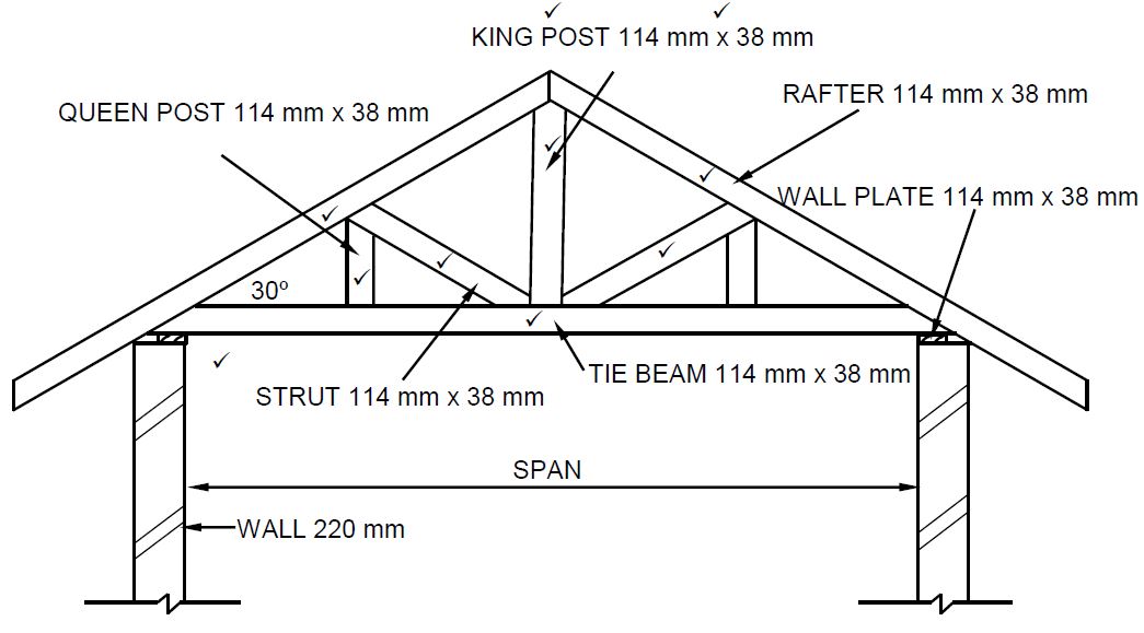
(not to scale)
| ASSESSMENT CRITERIA | MARK |
| Correctness of drawing: | |
| Rafters | 2 |
| King post | 1 |
| Tie beam | 1 |
| Queen post | 1 |
| Struts | 2 |
| Wall plate | 1 |
| Any ONE label with dimensions | 2 |
| TOTAL: | 10 |
3.14
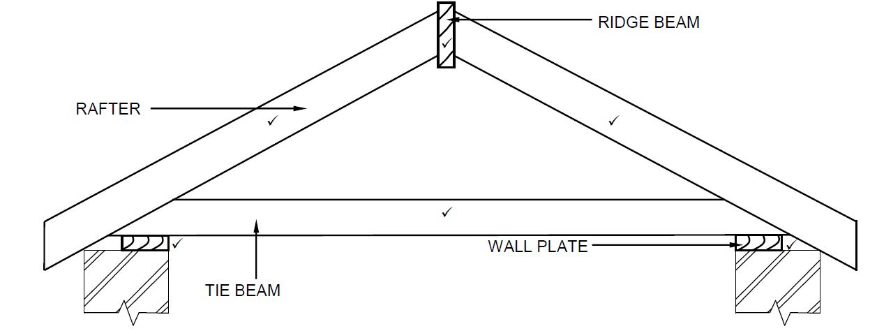
(not to scale)
| ASSESSMENT CRITERIA | MARK |
| Correctness of drawing: | |
| Tie beam | 1 |
| Rafters | 2 |
| Ridge beam | 1 |
| Wall plates | 2 |
| Application of scale: One or Two incorrect Three or Four incorrect More than Five incorrect | 2 |
| TOTAL | 8 |
QUESTION 4: EXCAVATIONS, FORMWORK, TOOLS, EQUIPMENT AND MATERIALS (SPECIFIC)
4.1
4.1.1 D (1)
4.1.2 H (1)
4.1.3 E (1)
4.1.4 I (1)
4.1.5 J (1)
4.1.6 G (1)
4.1.7 A (1)
4.1.8 F (1)
4.2 Consequences of neglecting to determine the location of services:
- This may affect/hamper/delay the excavation/construction process.
- It may have unplanned cost implications.
- Damage to services may occur.
- Injuries may occur.
ANY ONE OF THE ABOVE (1)
4.3 Safety precautions at night:
- The excavation must be well-lit at night.
- Red or orange warning lights should be visible.
- Fence off the area.
- Post visible warning signs.
- Wear appropriate visible PPE.
ANY THREE OF THE ABOVE
(3)
4.4
4.4.1 Members omitted:
- Walling boards
- Folding wedges/Wedge
- Struts
ANY TWO OF THE ABOVE
Consequence:
- The excavation could collapse. (3)
4.4.2
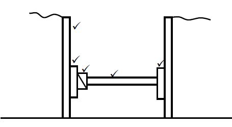
| ASSESSMENT CRITERIA | MARK |
| Correctness of drawing: | |
| Poling boards | 1 |
| Walling boards | 2 |
| Folding wedges | 1 |
| Strut | 1 |
| TOTAL: | 5 |
(5)
4.5
4.5.1 The removal of the formwork. (1)
4.5.2
- Applied to the interior surfaces of the formwork for quick release of the formwork.
- Ensures that formwork does not stick to the concrete.
ANY ONE OF THE ABOVE (1)
4.5.3 The bottom board that supports freshly poured concrete. (1)
4.6
4.6.1 Formwork for a concrete beam with floor slab. (1)
4.6.2
- – Cleats
- – Fixing plate/Kicker plates
- – Shutter board/Soffit board sides
- – Bearer/Head tree
- - Brace/Strut (5)
4.7
4.7.1 Personal protective equipment:
- Gloves
- Safety boots/Gumboots/Boots
- Overall
- Safety glasses
- Earmuffs/Earplugs
- Dust mask
- Hard hat/Safety helmet
ANY THREE OF THE ABOVE (3)
4.7.2 Methods to prevent rusting:
- Remove water from the drum.
- Oil the inside of the drum.
- Store concrete mixer with the opening of drum facing downwards.
ANY ONE OF THE ABOVE (1)
4.8 Strength - Cube test
Workability - Slump test (2)
4.9 24 hours/7 days/14 days/28 days (1)
4.10
- Non–Ferrous metals
- Ferrous metals
- Alloys
ANY TWO OF THE ABOVE (2)
4.11 Reasons for cladding a wall:
- To protect walls against weather elements like rainwater and wind.
- For aesthetical purposes.
- For functional purposes.
- For insulation purposes.
- To cover defects/imperfections.
ANY TWO OF THE ABOVE (2) [40]
QUESTION 5: PLASTER AND SCREED, BRICKWORK AND GRAPHICS AS MEANS OF COMMUNICATION (SPECIFIC)
5.1
5.1.1
C - Wet/Prepare/Clean the wall
B - Apply the plaster
D - Level/Cut the plaster/Removing access plaster (Sawing movement)
A - Smoothen/Float/Finish the surface (8)
5.1.2 Purpose of wetting the wall:
- If not done, the plaster will not stick properly to the wall.
- If not done, the plaster will dry out too quickly.
- If not done, the strength of the plaster will be affected
ANY ONE OF THE ABOVE (1)
5.1.3 Builder’s lime/Lime (1)
5.2
5.2.1 Jointing:
- River sand/Plaster sand is used as grouting between paving blocks/bricks.
- Mixture of plaster sand and cement is used as grouting between paving blocks/bricks.
ANY ONE OF THE ABOVE (1)
5.2.2 Bedding sand:
The final layer upon which the paving units are laid. (1)
5.2.3 Walkways:
Paving is subjected to only pedestrian use. (1)
5.3
5.3.1
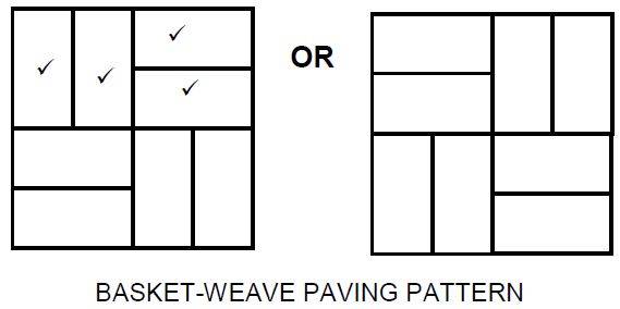
| ASSESSMENT CRITERIA | MARK |
| Vertical first and second full bricks | 2 |
| Horizontal first and second full bricks | 2 |
| Creating pattern | 1 |
| TOTAL: | 5 |
(5)
5.3.2
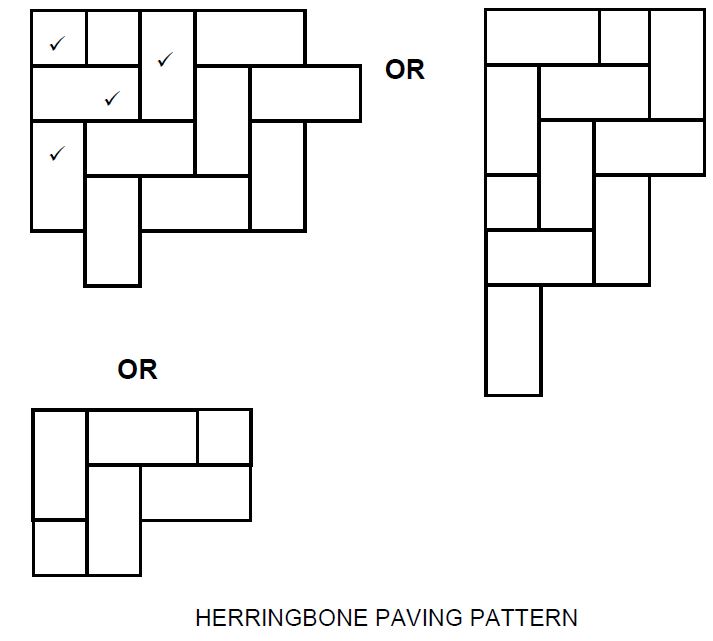
| ASSESSMENT CRITERIA | MARK |
| Half brick | 1 |
| Full bricks to create pattern | 3 |
| Creating pattern | 1 |
| TOTAL: | 5 |
(5)
5.4
5.4.1 To hold the two skins (walls) of the cavity wall together. (1)
5.4.2 Weep holes must be positioned:
- Above the horizontal damp-proof course of the external wall.
- On the same level as the concrete floor.
- Above the lintel on top of the window/door opening.
- Minimum 150 mm above NGL.
ANY ONE OF THE ABOVE (1)
5.4.3
- Water that penetrates the outside wall can drain out through the weep hole.
- For ventilation purposes.
ANY ONE OF THE ABOVE (1)
5.5
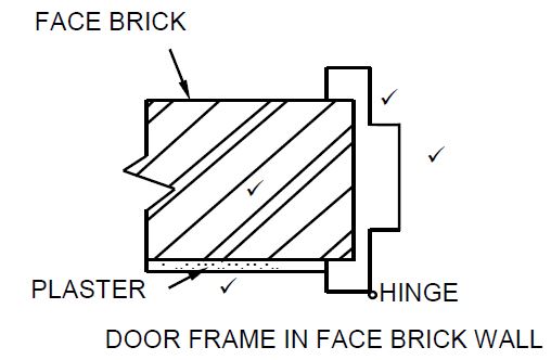
| ASSESSMENT CRITERIA | MARK |
| Face brick wall (Correct hatching) | 1 |
| Plaster | 1 |
| Steel door frame | 2 |
| 4 |
QUESTION 6: REINFORCEMENT IN CONCRETE, FOUNDATIONS, CONCRETE FLOORS AND QUANTITIES (SPECIFIC)
6.1
6.1.1 C (1)
6.1.2 C (1)
6.1.3 A (1)
6.1.4 D (1)
6.1.5 A (1)
6.2 1 500 mm (1)
6.3 90 mm (1)
6.4 On the load bearing wall. (1)
6.5 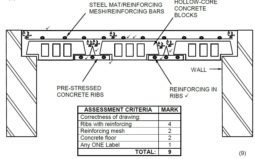
6.6
6.6.1 Main bar (1)
6.6.2 Anchor bar/Pressure bar/Compression bar (1)
6.6.3 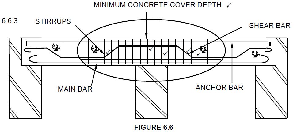
| ASSESSMENT CRITERIA | MARK |
| Correctness of drawing: | |
| Binders close spacing | 1 |
| Binders bigger spacing | 1 |
| Shear bar | 3 |
| Minimum concrete cover depth | 1 |
| 6 |
(6)
6.7 Minimum cover depth in reinforced concrete is important:
- To protect the steel against corrosion.
- To ensure adequate bonding between the steel and the concrete.
- To ensure adequate protection of steel in the event of a fire.
ANY TWO OF THE ABOVE (2)
6.8
6.8.1 40 mm (1)
6.8.2 30 mm (1)
6.8.3 60 mm (1)
| 6.9.1 | A | B | C | D | |
| Total length of damp-proof course needed for outer walls: | |||||
| 2/ | 8,5 | 17 m | Length of the long wall = 8 500 mm | ||
| 2/ | 4 | 8 m | Length of the short wall = 4 000 mm | ||
| 25 m | |||||
| OR | |||||
| 2/8 500 = 17 000 | |||||
| 2/4 000 = 8 000 | |||||
| 25 000 | |||||
| 25 m damp-proof course needed | (6) | ||||
| 6.9.2 | Number of bricks for inner wall | ||||
| 1/ | 2,78 | Length of inner wall: 3 000 – 220 = 2780 mm | |||
| 2,6 | Height of inner wall: 2 600 mm | ||||
| 50 | Use 50 bricks/m² for half brick wall | ||||
| 361,4/ 362 bricks | 362 Bricks needed for the inner wall. | (4) |
[40]
TOTAL: 200