CIVIL TECHNOLOGY(CIVIL SERVICES) GRADE 12 MEMORANDUM - NSC PAST PAPERS AND MEMOS NOVEMBER 2021
Share via Whatsapp Join our WhatsApp Group Join our Telegram GroupINSTRUCTIONS FOR THE MARKERS
- Markers should:
- Familiarise themselves with the question and answer before evaluating the responses of candidates.
- Always interpret the responses of the candidates within the context of the question.
- Consider any relevant and acceptable answer during pre-marking but should strictly adhere to the answers after finalisation of the marking guidelines.
- There are two approaches to answering questions, these are (1) to describe and (2) to explain.
- If a candidate is required to explain e.g., a process in 4 steps, only the first 4 responses should be considered.
- If, however a candidate is required to e.g. explain or describe how to transfer heights from one point to another using a transparent pipe level we need to consider that candidates may write a long description not necessarily well organised as an intellectual response may do. In this case the marker needs to evaluate the complete statement to judge if the candidate explained the required outcome satisfactorily and allocate marks on merit. The marker should apply his/her professional judgement with these types of questions.
- Mark what the candidate wrote and do not award marks for answers that the marker thinks the candidate meant with what was written.
- Indicate the tick or cross right at the position where the mark needs to be awarded or where the candidate made the error.
- Accept the letter corresponding with the correct answer as well as the answer written in full in multiple-choice questions.
- Accept incorrect spelling in one-word answers unless the spelling changes the meaning of the answer.
- For calculations:
- A mark is only awarded if the correct unit is written next to the answer.
- If TWO marks are awarded, ONE mark is awarded for the answer and ONE mark for the correct unit.
- Where the candidate made a principle error, e.g. use an incorrect method to calculate the answer, marks will be awarded for the correct values used in the calculation. No marks will be awarded for the answer of the incorrect method that was followed.
- Where an incorrect answer could be carried over to the next step, the first answer will be deemed incorrect. However, should the incorrect answer be carried over correctly, the marker has to recalculate the values, using the incorrect answer from the first calculation. If correctly used, the candidate should receive the full marks for subsequent calculations.
- Markers should consider when and where a candidate has rounded off in a calculation, as well as the subsequent effect it has on the final answer obtained. The mark for calculations should therefore be awarded on merit.
- Alternative methods of calculations must be considered, provided that the correct answer is obtained.
- When marking drawings:
- The member for which the mark should be awarded should be drawn correctly in the correct position to receive a mark.
- A member incorrectly drawn but wrongfully repeated in another position will be awarded the mark for the repeated incorrect member, provided that the marking guidelines provide for TWO or more marks for that member (positive marking).
- Marks can only be awarded for a label if the label is correctly indicating the correct member.
- Scale drawings should always be marked using an appropriate mask.
When a candidate drew the wrong drawing, e.g.: - A horizontal sectional view instead of a vertical sectional view, no marks will be allocated to the drawing as the candidate did not respond to the expected outcome.
- An orthographic view instead of a sectional view, no marks will be allocated to the drawing as the candidate did not respond to the expected outcome.
- An orthographic view instead of an isometric view, no marks will be allocated to the drawing as the candidate did not respond to the expected outcome.
QUESTION 1: OHSA, SAFETY, MATERIALS, TOOLS, EQUIPMENT AND JOINING (GENERIC)
1.1
1.1.1 Galvanising (1)
1.1.2 Paint (1)
1.1.3 Electroplating (1)
1.1.4 Curing (1)
1.1.5 Powder coating (1)
1.2
1.2.1 Scaffolding must be:
- Properly propped against displacement.
- Able to carry the mass or load.
- Securely and effectively braced to ensure stability/Stable.
- Secured at suitable vertical and horizontal distances to the structure.
- Free of defects/sharp edges.
- Constructed so that it has a safety factor of at least two.
- Levelled.
- Inspected regularly.
ANY TWO OF THE ABOVE (2)
1.2.2 Toe-board/Kickboard (1)
1.2.3 When working on scaffolding:
- Wear a safety harness/safety equipment/PPE.
- Do not throw any materials from a scaffold.
- Do not throw any tools from a scaffold.
- Never jump from a scaffold.
- Do not overload a scaffold.
- Remove or cover sharp edges or corners of a scaffold.
- Scaffolds should be kept free of waste/obstructions.
ANY TWO OF THE ABOVE (2)
1.3 To remove waste:
- Use a chute/pipe chute
- Use a conveyor belt/ramp
- Use a bucket with a rope/pulley system
- Use a forklift/mobi-lift/TLB/crane with a bucket/builders’ hoist
ANY TWO OF THE ABOVE (2)
1.4 Safe use of trestle scaffolds:
- Scaffolds should be soundly constructed of solid material.
- All precautionary measures should be taken to prevent the unexpected spreading of its supporting legs when in use.
- Trestles should not exceed a height of 3 m.
- Trestles scaffolds should not consist of more than two tiers.
ANY TWO OF THE ABOVE (2)
1.5 Hoisting materials and equipment in a builder’s hoist:
- Materials and equipment should be firmly stacked.
- Materials and equipment should be correctly stacked.
- Materials and equipment should be properly secured.
- Gates must be shut when in use.
- Overhead protection must be provided.
- Qualified person must operate the builders' hoist.
- Emergency brake mechanism must be installed.
- Not exceed the working capacity of the hoist/Not overload the hoist.
- Safety measures must be displayed inside the cage.
ANY ONE OF THE ABOVE (1)
1.6
- Drill a hole through the two metal plates.
- Insert the bolt into the drilled holes.
- Fasten the two plates with a bolt and nut.
(3)
1.7 Used to locate:
- Materials behind walls.
- Materials in ceilings.
- Materials under floors.
- Steel bars
- Copper pipes
- Ferrous metals
- Non-ferrous metals
- Electrical wiring
- Services
- Wood/Wooden/metal studs behind walls.
- The distance to and from an object.
ANY ONE OF THE ABOVE (1)
Care
Protect the multi-detector against:
- Moisture/Water/Corrosion
- Direct sunlight/heat
- Extreme temperature changes
- Bumps/Falling
- Damage caused by the release of acid from the battery
ANY ONE OF THE ABOVE (1)
[20]
QUESTION 2: GRAPHICS AS MEANS OF COMMUNICATION (GENERIC)
ANSWER SHEET 2
| NO. | QUESTIONS | ANSWERS | MARKS |
| 1 | Identify the scale you will use for the site plan and the floor plan respectively. | 1 : 200 1 : 100 | 2 |
| 2 | Who is responsible to verify all dimensions and levels on site before commencing work? | Contractors | 1 |
| 3 | What type of fencing does the architect recommend for the new dwelling? | Palisade fencing/Palisade | 1 |
| 4 | State the colour that you would use to indicate the new dwelling on the site plan. | Red | 1 |
| 5 | Identify number 1 | Boundary line | 1 |
| 6 | Identify number 2 | Building line | 1 |
| 7 | Identify number 3 | Electricity meter/Watt meter | 1 |
| 8 | Identify number 4 | Entrance/Exit/Driveway | 1 |
| 9 | Identify number 5 | Water storage tank/Water tank | 1 |
| 10 | Identify number 6 | Pavement/Walkway/Sidewalk | 1 |
| 11 | Identify number 7 | North point/North symbol/North sign/North direction | 1 |
| 12 | Identify number 8 | Municipal connection/Municipal manhole/Main sewer connection | 1 |
| 13 | Identify number 9 | Manhole | 1 |
| 14 | Determine the distance between number 2 and the new dwelling on the eastern side of the building. | 4 000 mm/4 m | 1 |
| 15 | Deduce the plot number of the new dwelling from FIGURE A. | Plot 31 | 1 |
| 16 | Which elevation is the closest to Loerie Street? | South elevation/South | 1 |
| 17 | What is the plot number of the property on the western side of the dwelling? | Plot 35 | 1 |
| 18 | Deduce TWO faults on FIGURE B. | No window in the dining room 110 mm of outside wall is incorrect/ Internal wall thickness Light switch in bathroom is in wrong place 220 mm inside wall in room A is incorrect/External wall thickness No step at the kitchen door No door in dining room/living room/door opening No arch indicated at dining room/living room Floor covering not indicated in rooms No socket outlets/plugs in rooms No hatching of floor plan No ceiling light in passage No dashed/hidden detail lines shown between living/dining/kitchen ANY TWO OF THE ABOVE | 2 |
| 19 | Which natural feature is indicated on the site plan? | Trees/Shrubs | 1 |
| 20 | What is wrong with the electrical installation in the bathroom in FIGURE B? | The light switch is fitted on the inside of the bathroom/Switch is incorrectly placed. | 1 |
| 21 | Identify number 10. | Ramp | 1 |
| 22 | Identify number 11. | Sink–double bowl/ Double bowl sink/Double sink | 1 |
| 23 | Identify number 12. | Two-way switch | 1 |
| 24 | Identify number 13. | One-way switch single-pole/One-way switch/Single-pole switch | 1 |
| 25 | Draw the symbol of a socket outlet. |  | 2 |
| 26 | Draw the symbol for a shower. |  | 2 |
| 27 | Draw the symbol for a wall-mounted light. | | 2 |
| 28 | Recommend TWO uses for ROOM A. | Dressing room/Walk-in closet En-suite/Bathroom Gym/Gymnasium Study/Office Store/Rest/Baby/Play/Games/ Guest/TV room Laundry ANY TWO OF THE ABOVE | 2 |
| 29 | Calculate the omitted horizontal dimension on the site plan. Give your answer in mm. Show ALL calculations. | 24 500 – 5 000 – 9 000 – 3 000 – 5 000 = 2 500 mm ANY OTHER CALCULATION METHOD TO ARRIVE AT THE ANSWER | 6 |
| TOTAL: | 40 |
QUESTION 3: CONSTRUCTION ASSOCIATED WITH CIVIL SERVICES, OHSA AND QUANTITIES (SPECIFIC)
3.1 Two methods used to prevent inhaling of dangerous fumes:
- Wear a respiratory mask.
- Use an extractor fan to remove the fumes.
- Use a blower to remove the fumes.
- Ventilate manhole.
- Wear a breathing apparatus like gas masks/oxygen tanks.
ANY TWO OF THE ABOVE (2)
3.2 Two aspects when setting out and excavating a trench:
- The slope of the trench should be determined.
- Invert levels must be correctly set out and verified.
- Type of soil.
- The excavation must be set out.
ANY TWO OF THE ABOVE (2)
3.3 Strut (1)
3.4
3.4.1 Concrete ring manhole (1)
3.4.2
- Step irons
- Reducer slabs
- Cover slabs
- Concrete lid/Lid/Steel cover/Manhole cover/
Concrete cover/Cover/Drain cover
ANY ONE OF THE ABOVE
(1)
3.4.3
- Excavate the hole at least 300 mm wider than the manhole rings.
- Allow extra depth for the thickness of the base, below the invert level of the drain.
- Cast the concrete base. (3)
3.5 In sound, intact rock/Rock (1)
3.6
- The slope of cuttings in permanent excavations shall not be steeper than 1:2.
- The excavation shall be sloped so that no water ponds within 3 m of the toe of the cutting.
- Surface water shall be diverted away and prevented from running down the cut and causing erosion.
ANY TWO OF THE ABOVE (2)
ANSWER SHEET 3.7
| A | B | C | D |
| NUMBER OF BRICKS | |||
| 2/ | 6,22 m | ||
| 1,2 m | |||
| 50 | 746,4 bricks | 747 bricks | |
| OR | |||
| 1/ | 6,22 m | ||
| 1,2 m | |||
| 100 | 746,4 bricks | 747 bricks | |
| OR | |||
| AREA OF WALLS | |||
| 1/ | 6,22 m | Centre line of walls = 6,22 m | |
| 1,2 m | 7,46 m² | Height of wall for manhole = 1 200 mm | |
| Area of walls is 7,46 m² | |||
| 3 Marks | |||
| NUMBER OF BRICKS | |||
| 2/ | 7,46 | Area of walls = 7,46 m² | |
| 50 | 746,4 bricks | Height of wall for manhole = 1 200 mm | |
| 50 bricks per m² for a ½ wall | |||
| 747 bricks are needed | |||
| 5 Marks |
3.8
3.8.1 Header course (1)
3.8.2 Queen closer/Closer (1)
3.8.3 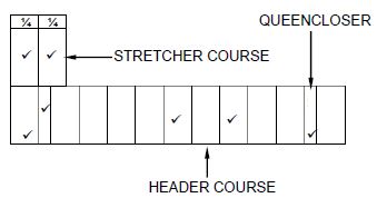
| ASSESSMENT CRITERIA | MARK |
| Correctness of drawing: | |
| Queen closers | 2 |
| Header course | 2 |
| Stretcher course | 3 |
| TOTAL: | 7 |
[30]
QUESTION 4: HOT AND COLD WATER SUPPLY, TOOLS, EQUIPMENT AND MATERIALS (SPECIFIC)
4.1
4.1.1 E
4.1.2 I
4.1.3 B
4.1.4 H
4.1.5 D
4.1.6 C
4.1.7 J
4.1.8 A
(8)
4.2
- Using the same type of material throughout a system.
- Use a non–metallic coupler when joining galvanised pipes to copper pipes.
(2)
4.3
4.3.1 To control water coming into the cistern/regulate the water level. (1)
4.3.2
- When the water level drops, the lever arm with the ball also drops and opens the valve.
- As water enters the system, the water level rises and the lever arm with the ball also rises.
- The lever arm pushes against the plunger and closes the valve. (3)
4.4
4.4.1 135° bend with inspection eye. (1)
4.4.2
- Allows access to the pipeline
- Allows for inspection
- Clearing/Cleaning of blockages
ANY TWO OF THE ABOVE (2)
4.5 This unit has a LED sensor that shuts off the water flow when it detects no movement under the showerhead. (2)
4.6
4.6.1 ![]()
(2)
4.6.2 
(2)
4.7
- 3(1)
- 4 (1)
- 2 (1)
- 5 (1)
- 1 (1)
4.8 Airlocks: Is caused by air (gas) that is trapped in a high point of the hot water system.
Water hammer: Is the noise and hammering of water pipes caused by poor installation of pipes/loose pipes.
(2)
4.9
4.9.1
- Test and replace thermostat, if faulty.
- Test and replace safety valve if faulty.
- Clean the safety valve/thermostat sleeve.
ANY ONE OF THE ABOVE (1)
4.9.2
- Clear blockages in pipes.
- Clear blockages in valves.
- Replace low pressure geyser with high pressure geyser.
- Replace faulty valves.
- Install a pressure pump/pump (1)
ANY ONE OF THE ABOVE
4.10 Solar geyser should be placed on the roof of the dwelling/facing north in direct sunlight.
High pressure electric geyser can be placed in the ceiling/against the external wall/on the floor. (2)
4.11
4.11.1 Pipe-thread cutting machine (1)
4.11.2 The reamer is used to clean out the burr after the pipe has been cut. (1)
4.11.3 To prevent accidental starting of the machine/injuring workers. (1)
4.12 Drain cleaning rods/Jetting machine/Drain cleaning machine (1)
4.13 When the blocked water starts to flow. (1)
4.14
- Drain cleaning machine
- Jetting machine
ANY ONE OF THE ABOVE (1)
[40]
QUESTION 5: GRAPHICS AS MEANS OF COMMUNICATION, ROOF WORK AND STORM WATER (SPECIFIC)
5.1
- Discomfort of occupants or public.
- Loss of life.
- Damage to properties.
- Pollution of the environment.
- Negative environmental impact/Soil erosion.
- Will overflow/Cause flooding/Cause blockages.
ANY TWO OF THE ABOVE (2)
5.2 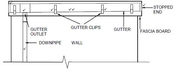
DRAWING NOT TO SCALE
USE A MASK TO MARK THIS QUESTION.
DOWN PIPE AND SLOPE CAN BE DRAWN ON THE OTHER SIDE OF THE WALL AS WELL.
APPLICATION OF SCALE:
| ASSESSMENT CRITERIA | MARKS |
| Correctness of drawing: | |
| Gutter | 1 |
| Slope of gutter | 1 |
| Gutter clips | 2 |
| Stopped end | 2 |
| Gutter outlet | 1 |
| Square downpipe | 1 |
| Application of scale | 1 |
| TOTAL: | 9 |
5.3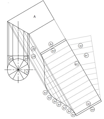
| NO | ASSESSMENT CRITERIA | MARK |
| Correctness of drawing: | ||
| 1 | Dividing circle in 12 parts (top view) | 1 |
| 2 | Projection lines | 4 |
| 3 | Dividing circumference plan view into 12 parts (Any acceptable method) | 2 |
| 4 | Outside lines of base and sides | 3 |
| 5 | Outside lines of development | 7 |
| 6 | 3 mm seam on both sides | 2 |
| TOTAL: | 19 |
- A MAXIMUM OF 17 MARKSWILL BE AWARDED IF THE DEVELOPMENT OF PIPE A WAS NOT CORRECTLY PROJECTED.
- A MAXIMUM OF 5 MARKS WILL BE AWARDED IF PIPE A WAS NOT DEVELOPED (1
MARK - DIVIDING CIRCLE; 2
MARKS - VERTICAL
PROJECTION LINES; 2
MARKS - DIVIDING CIRCUMFERENCE)
QUESTION 6: SEWERAGE, SANITARY FITTINGS AND JOINING (SPECIFIC)
6.1
6.1.1 B (1)
6.1.2 B (1)
6.1.3 C (1)
6.1.4 A (1)
6.1.5 A (1)
6.2
6.2.1 Flux:
- Cleans the joint/pipe.
- Allows solder to flow around joint/adhere to the joint.
- Prevents oxidation.
ANY ONE OF THE ABOVE (1)
6.2.2 Heat the joint and apply solder to complete the joint. (2)
6.3
6.3.1 Compression T-joint/T-joint/ T (1)
6.3.2 Compression ring/Ferrule (1)
6.3.3 The compression ring tightens against the compression nut and threaded piece to form a watertight joint/Prevent leak. (1)
6.4 Solvent weld/PVC weld/PVC adhesive/PVC glue/PVC cement (1)
6.5
- Ensure that the pipe installation is protected from any external pressure.
- Pipes must be easily fixed in case of a leak, without causing damage to the building.
- Plastic pipes should not be rigidly encased in floors, concrete slabs or walls.
- Plastic pipes passing through a wall should preferably be installed inside a sleeve.
- Where a sanitary drainpipe and a pipe that conveys potable water are laid underground horizontally next to each other, they shall be laid at least 500 mm apart.
- When a sanitary drainpipe and a pipe that conveys potable water cross each other, the pipe that conveys the water shall be laid at least 100 mm above the line of the sockets of the drainpipe.
- In the case of pipework with flexible joints, adequate measures shall be taken to prevent movement of the pipework due to water pressure effects. Thrust blocks shall be designed and installed in accordance with SANS 1200 L.
ANY ONE OF THE ABOVE (1)
6.6
6.6.1
- - Receives solid waste for decomposition.
- - Stores excess water until discharged into the French drain. (2)
6.6.2 The purpose of the manhole cover is to:
- Gain access to the septic tank.
- Inspect the septic tank.
- Clean the septic tank.
- To prevent people from falling into the manhole.
- To prevent foul gasses from escaping.
ANY ONE OF THE ABOVE (1)
6.6.3 Bacteria (1)
6.6.4
- The soap and chemicals in the water will kill/disturb the bacteria.
- Septic tank and French drain will become saturated, and drains will block/overflow.
- Solid waste will not decompose.
ANY ONE OF THE ABOVE (1)
6.6.5 French drain (1)
6.7 The pipe fittings when connected to pipes must be:
- Made of suitable material.
- Watertight under normal working conditions.
- Able to withstand internal water pressure of 50 kPa and external pressure of 30 kPa.
ANY TWO OF THE ABOVE (2)
ANSWER SHEET 6.8
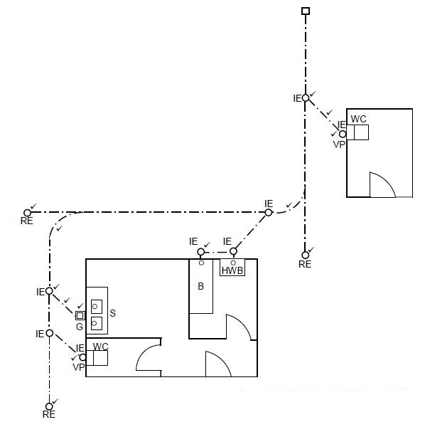
GULLY CAN BE PLACED AT THE KITCHEN OR THE BATHROOM ALTERNATIVE ABBREVIATION FOR VENTPIPE IS VV/SVP CURVES AT MAIN SEWER PIPES CAN BE REPLACED BY A 45° LINE (13)
| ASSESSMENT CRITERIA | MARK |
| Correctness of drawing: | |
| Branch pipes (ANY TWO) | 2 |
| Vent pipe | 2 |
| Gully | 1 |
| Junction of two main sewer pipes | 2 |
| Rodding eyes | 3 |
| Inspection eyes (ANY THREE) | 3 |
| TOTAL: | 13 |
6.9 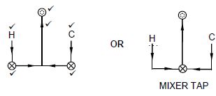
| ASSESSMENT CRITERIA | MARK |
| Correctness of drawing: | |
| Hot and cold-water inlet pipes | 2 |
| Cold water stopcock | 1 |
| Hot water stopcock | 1 |
| Direction of flow in all pipes | 1 |
| Shower rose | 1 |
| TOTAL: | 6 |
[40]
TOTAL: 200