MECHANICAL TECHNOLOGY (WELDING AND METALWORK) GRADE 12 MEMORANDUM - NSC EXAMS PAST PAPERS AND MEMOS NOVEMBER 2020
Share via Whatsapp Join our WhatsApp Group Join our Telegram GroupMECHANICAL TECHNOLOGY: WELDING AND METALWORK
GRADE 12
NOVEMBER 2020
MEMORANDUM
NATIONAL SENIOR CERTIFICATE
QUESTION 1: MULTIPLE-CHOICE QUESTIONS (GENERIC)
1.1 A ✓(1)
1.2 D ✓ (1)
1.3 A ✓ (1)
1.4 C ✓ (1)
1.5 B ✓ (1)
1.6 B ✓ (1)
[6]
QUESTION 2: SAFETY (GENERIC)
2.1 Work procedures on machine:
Switch off machine. ✓ (1)
2.2 The horizontal band saw:
- No adjustments to machine or work piece✓
- Ensure sufficient coolant on work piece and blade. ✓
- Do not leave machine unattended while in operation. ✓
- Do not lean on machine.✓
- Keep hands clear from blade. ✓
(Any 2 x 1)(2)
2.3 Surgical gloves:
- Prevent contamination of wound✓
- To prevent transmission of HIV/AIDS or any blood related diseases to the first aid helper. ✓(2)
2.4 Personal protective equipment (PPE) during arc welding:
- Welding helmet / Helmet✓
- Safety goggles / Face shield ✓
- Leather apron / Apron✓
- Leather gloves / Gloves ✓
- Leather spat / Spats ✓
- Safety boots / Safety shoes ✓
- Over-all ✓
- Skull cap✓
- Neck protection ✓
- Ear plugs / Ear muffs. ✓
- Respirator ✓
(Any 2 x 1) (2)
2.5 Responsibility of the employer regarding the health and safety:
- Sufficient lighting ✓✓
- Sufficient ventilation✓✓
- Provide first-aid equipment✓✓
- Provide a safe / clean working environment ✓✓
- Provide personal protective equipment (PPE) ✓✓
- Provide safety training to employees ✓✓
(Any 1 x 2) (2)
2.6 Responsible for administering first aid:
A qualified / trained first aid person ✓(1)
[10]
QUESTION 3: MATERIALS (GENERIC)
3.1 Tests to identify various metals:
3.1.1 Sound test:
- Tapping the metal with a hammer (any metal object) ✓ and identify the sound. ✓
- Dropping the metal on the floor ✓and identify the sound.✓
(Any 1 x 2) (2)
3.1.2 File test:
File the metal and pay attention to the bite of the file into the metal.✓The bigger the bite the softer the metal. OR The smaller the bite the harder the metal.✓ (2)
3.2 Purpose of heat treatment of steel:
- To change ✓ the properties ✓ of steel.
- To change ✓the grain structure ✓ of steel.
(Any 1 x 2) (2)
3.3 Purpose of case hardening on steel:
To create a hard / wear resistance surface / case ✓ with a tough core. ✓ (2)
3.4 The tempering process for steel:
- Heat the steel to a temperature (temper colour) below the critical temperature. ✓
- Soak it at that temperature for a period.✓
- Quench / cool in an appropriate quenching agent. ✓ (water, brine, or oil) (3)
3.5 THREE factors for heat treatment of steel:
- Heating temperature / Carbon content ✓
- Soaking (Time period at temperature) / Work piece size✓
- Cooling rate / Quenching rate (Quenching medium) ✓ (3)
[14]
QUESTION 4: MULTIPLE-CHOICE QUESTIONS (SPECIFIC)
4.1 B / D ✓ (1)
4.2 A ✓ (1)
4.3 C ✓ (1)
4.4 D ✓ (1)
4.5 B ✓ (1)
4.6 D ✓ (1)
4.7 A ✓ (1)
4.8 C ✓ (1)
4.9 D ✓ (1)
4.10 C ✓ (1)
4.11 B ✓ (1)
4.12 C ✓ (1)
4.13 A ✓ (1)
4.14 D ✓ (1)
[14]
QUESTION 5: TERMINOLOGY (TEMPLATES) (SPECIFIC)
5.1 Advantages of templates:
- Quicker to use to improve mass production ✓
- Accurate production ✓
- Cheap to manufacture ✓
- Unskilled labour will be able to use it ✓
- Avoid unnecessary wastages / cost effective ✓
- Uniformity in production ✓
- Can be reused. ✓
(Any 2 x 1) (2)
5.2 Use of templates:
5.2.1 Thin metal is used for profile cutting machines ✓ (1)
5.2.2
- Hardboard templates is used for templates for gussets. ✓
- Hardboard templates are used for checking sizes. ✓
- Hardboard templates is used for marking of holes. ✓
(Any 1 x 1) (1)
5.3 Components of a roof truss:
- Rafter ✓
- Purlin ✓
- Internal bracing members / strut ✓
- Gusset plate ✓
- Main tie / Tie beam / Beam ✓ (5)
5.4 A mild steel ring material:
Calculate the dimensions of the required material:
Mean θ = Outside θ - plate thickness
= 280 - 12
= 268 mm
Mean circumference = π x meanθ
= π x 268
= 841,95mm
= 842 mm (5)
5.5 Abbreviation 'SANS':
South African ✓ National Standards ✓ (2)
5.6 Resistance weld:
5.6.1 Foil seam ✓ (1)
5.6.2 Flash or resistance butt ✓ (1)
5.7 Weld dimensions:
- 5 – size (width) of weld ✓
- 25 – length of weld ✓
- 50 – pitch of welds ✓ (3)
5.8 Position of the weld:
5.8.1 Weld on the arrow side ✓ (1)
5.8.2 Weld on both sides✓ (1)
[23]
QUESTION 6: TOOLS AND EQUIPMENT (SPECIFIC)
6.1 Pedestal drill machine:
- = Table / Machine table / Working table / Platform ✓
- = Chuck / Drill bit holder ✓
- = Motor ✓
- = Pillar / Column✓ (4)
6.2 Operating principles:
6.2.1 Horizontal band saw:
- The blade is tensioned around two pulleys. ✓
- The machine is driven by an electric motor.✓
- The blade is fitted so that it cuts in a continuously forward motion.✓
- The blade assembly is raised and lowered by hand or by hydraulic controls. ✓
- The metal being cut is held firmly in the stock clamp during the cutting process.✓
(Any 4 x 1) (4)
6.2.2 Punch and cropper (shear) machine:
- It is an electrically driven machine. ✓
- It makes use of a flywheel and clutches ✓ to engage various shearing blades or punches. ✓ (3)
6.3 Primary function of flashback arrestors:
It prevents ✓ back-feeding/backfiring. ✓✓ (3)
6.4 Use of taps and dies:
- Taps are used to cut / clean✓ internal / nut screw threads ✓
- Dies are used to cut / clean ✓ external / bolt screw threads ✓ (4)
[18]
QUESTION 7: FORCES (SPECIFIC)
7.1 Frameworks:
7.1.1 Force diagram: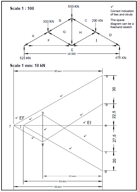
Markers need to draw the diagram to scale. (10)
7.1.2 Magnitude and nature of the members:
| MEMBER | MAGNITUDE (kN) | NATURE |
| AF | 1050 ✓ (1020 – 1080) | STRUT |
| BG | 760 ✓ (730 – 790) | STRUT |
| CH | 760 ✓ (730 – 790) | STRUT |
| DI | 960 ✓(930 – 990) | STRUT |
| FG | 300 ✓ (270 – 330) | STRUT |
| HI | 200 ✓ (170 – 230) | STRUT |
| FE | 930✓ (900 – 960) | TIE |
| GH | 250 ✓ (220 – 280) | TIE |
| IE | 830 ✓ (800 – 860) | TIE |
| Minus 2 marks for incorrect conversion (mm to kN) |
(18)
7.2 BEAMS:
7.2.1 Bending moments:
BMB = (3,4 x 3)
= 10,2 kN.m
BMC = (3,4 x l) - (4 x 4)
= 23,8 - 16
= 7,8 kN.m
BMD = 0 kN.m
7.2.2 Shear force diagram: (3)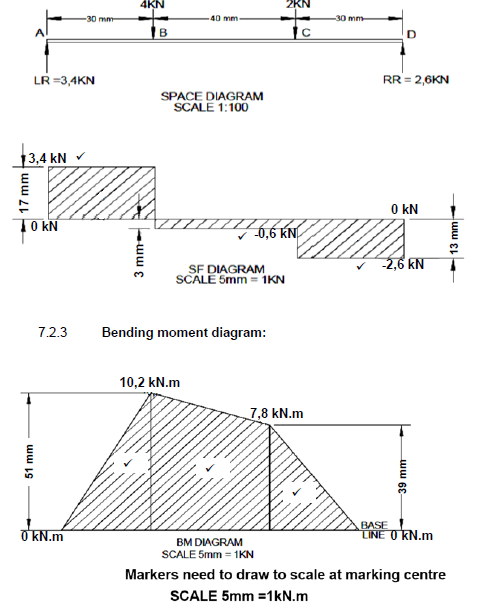
7.2.3 Bending moment diagram: (3)
7.3 Stress and Strain:
7.3.1 Maximum stress:
Maximum Stress = Maximum Load
Area
= 8 x 10 3
0,08 x 10-3
= 100 x 106 Pa
= 100 MPa (3)
7.3.2 Safe working stress:
Safe Stress = Maximum Stress
Safety Factor
= 100 x 106
4
= 25 x 106 Pa
= 25 MPa (2)
[45]
QUESTION 8: JOINING METHODS (INSPECTION OF WELDS) (SPECIFIC)
8.1 Welding spatter:
- Too high current / Amperage too high ✓
- Too long arc / Arc blow ✓
- Not using anti-spatter spray ✓
- Electrode angle too small ✓
- Welding speed too fast ✓
- Wet electrodes✓
- Gas-flow too high (gas welding)✓
- Incorrect polarity for electrode type✓
(Any 4 x 1) (4)
8.2 Gas cutting:
8.2.1 Nozzle too high from surface:
- Excessive melting of the top edge. ✓
- Undercut at the top of the cut face with lower part square and sharp bottom corner. ✓ (2)
8.2.2 Nozzle too close to the surface:
- Top edge slightly rounded and heavily beaded.✓
- Cut face usually square with fairly sharp bottom corner.✓ (2)
8.3 Causes of weld defects:
8.3.1 Porosity:
- Dirty weld surface ✓
- Wet welding electrodes ✓
- Rust in the MIG wire electrode✓
- Interruption of shielding gas supply✓
- Welding in windy conditions where effectiveness of shielding gas is compromised ✓
- Wrong gas used on the specific metal✓
- Weld ability of parent metal not good ✓
- Wrong electrode used on the specific metal ✓
- Too high temperature ✓ (Any 2 x 1) (2)
8.3.2 Poor penetration:
- Welding current is too low ✓
- Travel speed is too fast ✓
- Incorrect electrode angle ✓
- Poor edge preparation✓
- Insufficient root gap✓
- Gas flow too low (gas welding) ✓(Any 2 x 1) (2)
8.4 Heat Affected Zone (HAZ) Cracks:
- Excessive hydrogen ✓
- High residual stress levels (work piece cooled too fast) ✓
- High carbon content on the base metal ✓
(Any 2 x 1) (2)
8.5 Visual inspection:
- Shape of the profile ✓
- Uniformity of the surface ✓
- Overlap ✓
- Undercutting✓
- Penetration bead ✓
- Root groove ✓
- Surface cracks ✓
(Any 3 x 1) (3)
8.6 Ultrasonic test:
Gel should be put on the surface of the work piece.✓
- The sender/receiver is moved in a zigzag motion across the weld to broaden its detection range. ✓
- A high frequency sound wave is send into the metal. ✓
- When the wave is stopped, the sender serves then as a receiver. ✓
- The receiver monitors the waves as it is reflected through the metal. ✓
- Each wave is visually represented on an oscilloscope.✓
- The calibrated oscilloscope will then indicate the deviations in the waves which represents the defects in the metal.✓
(Any 6 x 1) (6)
[23]
QUESTION 9: JOINING METHODS (STRESSES AND DISTORTION) (SPECIFIC)
9.1 Residual stress:
Residual stresses are stresses that exist in a metal ✓after cooling✓ (2)
9.2 Effect of hot working on steel:
- In hot working, deformation and recrystallization occur simultaneously so that the rate of softening is greater than work hardening. ✓
- Hot-working should be finished at a temperature just above the recrystallization temperature. ✓
- To obtain a fine grain structure.✓
- If the finishing temperature is too high, grain growth will occur while the metal is cooling above the recrystallization temperature and inferior properties will develop. ✓ (4)
9.3 Iron-carbon diagram:
9.3.1 Iron-carbon equilibrium diagram ✓ (1)
9.3.2
- Temperature / Degrees Celsius ✓
- Austenite✓
- Austenite and Cementite ✓
- Ferrite and Pearlite ✓
- Carbon content ✓ (5)
9.4 Result when metal is cooled rapidly:
- The metal sets up internal and external stresses. ✓
- Causes cracks on the surface of the metal. ✓
- Causes deformation.✓
- Hardness increases.✓
- Martensite forms. ✓
(Any 2 x 1) (2)
9.5 Quenching media:
- Water ✓
- Brine✓
- Oil ✓
- Air ✓
- Metal / Molten salts ✓
- Lime✓
- Sand ✓
- Ash ✓
(Any 4 x 1) (4)
[18]
QUESTION 10: MAINTENANCE (SPECIFIC)
10.1 Types of maintenance:
- Preventative✓
- Reliable centred ✓
- Predictive✓
- Routine ✓
- Corrective ✓
- Condition based ✓
- Reactive maintenance ✓
(Any 2 x 1) (2)
10.2 Lockout on machines:
To ensure that nobody can turn on ✓the machine while maintenance is being carried out.✓ (2)
10.3 Rules to be observed before machine start up:
- Check if there is lock out tag✓
- Confirm that the machine is safe and operational.✓
- Check that all guards and safety devices are in position and operative. ✓
- Inform workers that the machine is being brought back into service. ✓
- Check that the area surrounding the machine is clear and that turning it on will not endanger anyone.✓
- Check that all relevant fasteners have been properly tightened.✓
- Check that all lockout devices have been removed.✓
- Turn on the machine's power supply. ✓
- Know where the stop switch or emergency switch is located. ✓
(Any 2 x 1) (2)
10.4 Factors to be observed when selecting the cutting speed of a drilling machine:
- Type of material ✓
- Diameter of drill bit ✓
- Material of which the drill bit is made ✓
- Type of drill bit ✓
- Firmness with which the work is clamped ✓
- Condition of the machine ✓
- Use of cutting fluids ✓
- Rate of feed ✓
(Any 3 x 1) (3)
[9]
QUESTION 11: DEVELOPMENT (SPECIFIC)
Square-to-round transition:
11.1 The true length FG:
IK = 300(2units)
IH = 150(1unit)
HK = 1√3 (1unit √3)
The true lengthFG:
Plan lengthFG = FK - GK
= 400 - 300
= 100mm
The true FG is equalto H'F
CG2 = C'F2 + FG2
= 4002 + 1002
C'G = √170000
CG = 412,31 mm
True length C'G = √412,312 + 8002
= 900mm
11.2 Length CI, the sides CE and EI of triangle CEI must be calculated:
CE = CF - EF
= 400 - 150
= 250mm
ButEI = FH
HK = 1unit x √3
= 150√3
= 259,81mm
FH = FK - HK
= 400 - 259,81
= 140,19mm
CI2 = CE2 + EI2
= 2502 + 140,192
= √82153,24
CI = 286,62mm
TruelengthCI CI PerpendicularHeight
= 286,622 + 8002
= √722151,02
= 849,79mm (10)
11.3 JI is one-twelfth of the circumference:
True Length of JI Circumference = π x MD/12
1/12 Circumference = 1884,9
12
= 157,08 mm (3)
[20]
GRAND TOTAL: 200