ELECTRICAL TECHNOLOGY (POWER SYSTEMS) GRADE 12 MEMORANDUM - NSC EXAMS PAST PAPERS AND MEMOS NOVEMBER 2020
Share via Whatsapp Join our WhatsApp Group Join our Telegram GroupELECTRICAL TECHNOLOGY: ELECTRONICS
GRADE 12
NOVEMBER 2020
MEMORANDUM
NATIONAL SENIOR CERTIFICATE
INSTRUCTIONS TO THE MARKERS
- All questions with multiple answers imply that any relevant, acceptable answer should be considered.
- Calculations:
2.1 All calculations must show the formulae.
2.2 Substitution of values must be done correctly.
2.3 All answers MUST contain the correct unit to be considered.
2.4 Alternative methods must be considered, provided that the correct answer is obtained.
2.5 Where an incorrect answer could be carried over to the next step, the first answer will be deemed incorrect. However, should the incorrect answer be carried over correctly, the marker has to re-calculate the values, using the incorrect answer from the first calculation. If correctly used, the candidate should receive the full marks for subsequent calculations. - These marking guidelines are only a guide with model answers. Alternative interpretations must be considered and marked on merit. However, this principle should be applied consistently throughout the marking session at ALL marking centres.
QUESTION 1: OCCUPATIONAL HEALTH AND SAFETY
1.1 Any article or part thereof which is manufactured, provided or installed ✓in the interest of the health or safety of any person.✓✓(2)
1.2 Your right to fair labour practices.✓✓
Your right to work reasonable hours.
Your right to belong to a trade union.
Your right to earn a living wage.
Your right not to be discriminated against. (1)
1.3
- If a person dies. ✓
- A major incident. ✓✓
- An incident where the health and safety of any person has been/was endangered. (2)
1.4
- To dismiss an employee without due process. ✓
- To reduce the rate of remuneration without due process. ✓
- Alter the terms of conditions of his/her employment to terms of conditions that is less favourable to him/herself. ✓
- Harassment and verbal abuse.
- Alter position relative to other people.
- Treat employees unfair because of race.
NOTE: If a learner only mentions an infringement of rights only 1 mark will be awarded. Duplicate mentioning of rights will not be awarded (3)
1.5 In an emergency it can be pushed and it would immediately cut all electric power ✓✓to all the equipment, stopping them,✓✓thus making the workshop safe.✓ (2)
[10]
QUESTION 2: RLC CIRCUITS
2.1
2.1.1 If VX lags VR by 35°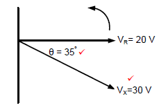
(2)
2.1.2 The voltages represent an RC circuit ✓ because, VR is always in phase with IT and VX lags VR by 35°. ✓
Because VR is in phase with IT and VX is lagging VR, thus proving that the circuit is predominantly capacitive as IT leads VX. (2)
2.2
2.2.1
XL = 2 x π x f x L
= 2 x π x 60 x 20 x 10-3
= 7,54 Ω (3)
OR
XL = VL
IT
XL = 49
6,5
XL = 7,54 Ω
2.2.2
VC = I x Xc
= 6.5 x 25
= 162,5 V (3)
2.2.3 The voltage is lagging, ✓ because the capacitive reactance is greater than the inductive reactance (VC is greater than VL). ✓(2)
2.2.4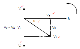
(5)
NOTE: 5 marks, 1 mark for each correct label of which VL, VC and VR are priority marks and thereafter any other two correct labels.
2.3 2.3.1 Phasor diagram of a parallel RLC✓ circuit at resonance. ✓ (2)
2.3.2 The voltage drop across the components in a parallel circuit is the same, ✓ hence the voltage is used as the reference. (1)
OR
The applied voltage is common across all components.
2.3.3 In a parallel resonant circuit impedance is at maximum, ✓ and the total current is at minimum. ✓ (2)
OR
The relationship between impedance and current in a parallel RLC circuit is inversely proportional.
2.4
2.4.1
fr = 1
2π√LC
= 1
2 x 3,142√300 x 10-3 x 150 x 10-6
= 23,73 Hz (3)
2.4.2
Q = 1/R x √L/C
= 1 x √300 x 10-3
20 150 x 10-6
= 2,24
(3)
OR
If candidates calculate XL or Xc they can use the following formulae:
XL = 2πfL
XL = 2π(23.73)(300 x 10-3)
XL = 44.73Ω
Q = XL/R
Q = 44.73
20
Q = 2,24
Q = XC/R
Q = 44.73
20
Q = 2,24
2.4.3
Z = 20Ω
Z = R at resonance (2)
2.4.4
C = 1
4 x π2 x L x fr2
= 1
4 x 9,87 x 300 x 10-3 x 4 x 106
= 2,111 x 10-8 F
= 21,11 nF (3)
OR
C = 1
(2πfr)2 x L
= 1
(2 x 3,14 x 2000)2 x 300 x 10-3
= 2,113 x 10-8 F
= 21,13 nF
For resonance. Calculating XL first and then since XL= XC
XL = 2πfL
XL = 2π(2000)(300 x 10-3)
= 3769.91Ω
C = 1
2πfXC
= 1
2π(2000)(3769.91)
= 21.11nF
2.5.
2.5.1 Q1 (1)
2.5.2 Reading the values from the graph where f1 = 30000 Hz and f2 = 35000 Hz the following can be deduced:
fr = f1 + f2
2
= 30000 + 35000
2
= 32500Hz
= 32,5 kHz (3)
NOTE: If the candidate deduced the value 32,5 kHz directly from the graph, full marks will be awarded.
Because the incorrect formula was provided on the formula sheet, the following calculation will be accepted.
fr = f1 + f2
2
= 35000 - 30000
2
= 2500Hz
2.5.3 Deducing the indicated bandwidth of Q1 from the graph as 35 kHz - 30 kHz the candidate will be able to calculate as follows:
BW = f - f
= 35000 - 30000
= 5000Hz
BW = fr
Q
Q = fr
BW
= 32500
5000
= 6,5
OR
BW = fr and BW=(f2 - f1)
Q
(f2 - f1) = fr
Q
Q = fr
(f2 - f1)
= 32500
(35000- 30000)
= 6,5 (3)
[40]
QUESTION 3: THREE-PHASE AC GENERATION
3.1 3.1.1 Reactive power is the power in an AC circuit when the current is out of phase with the voltage ✓ as a result of the capacitive and/or the inductive load. ✓
Reactive power is the power that is wasted and not used to do work on the load. (2)
NOTE: If only the formula is explained or written only 1 mark will be awarded.
3.1.2 Efficiency is the percentage ratio ✓ of the output power to the input power. ✓ (2)
NOTE: If only the formula is explained or written only 1 mark will be awarded.
3.2
VPH = VL
√3
=380
√3
= 219, 39 V (3)
3.3
3.3.1
- The load will draw more current from the supply. ✓
- Large cables may be needed to carry the current. ✓
- Maintenance cost will increase. ✓
- More heat will be generated in the cables. ✓(4)
3.3.2
- By adding power factor correction capacitors in parallel with a load. ✓
- Use synchronous motors in shunt (parallel) with the load.✓
- Make use of phase advancers. ✓
- Variable speed drives
- Soft starters (3)
3.4 Kilo-watt-hour meter/Energy meter. ✓ (1)
3.5
3.5.1
IL = √3 x IPH
= √3 x 30
= 51.96A
= 52A (3)
3.5.2
VL = VPH
= 380 V
ZPH = VPH
IPH
=380
30
= 12,67 Ω (5)
When candidates substitute Vph correctly as 380 V without calculating it, two additional marks should be awarded to the 3 mark calculation.
3.5.3
P= √3 x VL x IL x Cos θ
= √3 x 380 x 52 x 0,9
= 30,8 kW (3)
3.6
PT = P1 + P2
= 10000 + 3000
= 13000W
= 13kW (3)
3.7 A wattmeter is used to measure the input power/output power ✓ in an AC system.
Any acceptable application that uses a wattmeter to indicate power usage. (1)
[30]
QUESTION 4: THREE-PHASE TRANSFORMERS
4.1
- A step up transformer steps up alternating voltage ✓ from low voltage to high voltage ✓
- A step up transformer compensates for losses in a transmission system. (2)
4.2
- Overloading ✓
- Lack of ventilation ✓
- Insufficient oil ✓ (3)
4.3
- Oil Natural, Air Forced. ✓
- Oil Natural, Air Natural. ✓
- Oil Forced, Air Forced.
- Oil Forced, Water Forced. (2)
4.4
- Temperature rises ✓
- Insulation failure ✓
- Short circuits
- Gas forming due to oil breakdown
- Explosion (2)
4.5 If the load is increased, the secondary current will increase✓ resulting in an increase✓ in the primary current. This increase is due to the increased magnetic force that results due to higher current flow. (2)
4.6 Delta – star ✓
Star – delta ✓
Star – star
Delta – delta
Step-up
Step-down
Isolation transformer (2)
4.7
- Over current relay✓
- Balance earth fault relay ✓
- Restricted earth fault relay
- Standby earth fault relay
- Bucholtz relay
- Fuses
- Circuit breakers (2)
4.8 (3)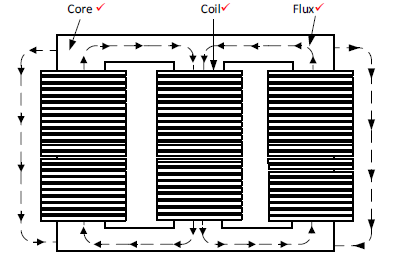
CORE-TYPE THREE-PHASE TRANSFORMER CONSTRUCTION
4.9
- Ensure the supply is switched off before wiring the transformer✓
- Never touch any electrical wires or terminals on an energised transformer with bare hands
- Wear safety gear (PPE)
- Be careful of the secondary terminals of a live open circuit transformer
- Use short wires and ensure that the wires are tightly connected
- Do not switch the circuit on before it is tested. (1)
4.10
4.10.1
POUT = 200000 x 0.85
= 170000W
η = POUT x 100
PIN
= 170000 x 100
171800
= 98.95% (5)
OR
If the learner calculated the input power by using the given line current, the following answer will be accepted.
PIN = √3VLIL x cosθ
= √3(11000)(30) x 0.85
= 485840.25W
η = POUT x 100
PIN
= 170000 x 100
485840.25
=34.99%
4.10.2
TR = Vph(1)
Vph(2)
= 11000
219,39
= 50 :1 (3)
4.10.3
IL(2) = S
√3 x VL(2)
=200000
√3 x 380
= 303,86 A
OR
IL(2) = P
√3Vcosθ
= 170000
√3 380 0.85
= 303.86A (3)
[30]
QUESTION 5: THREE-PHASE MOTORS AND STARTERS
5.1
- Check that the bolts securing the motor to the frame are tight. ✓
- Check that the end plates are fastened properly. ✓
- Check the bearings for smooth rotation.✓
- Check the movement of the shaft.
- Check for cracks in the housing. (3)
5.2
- It is cheaper and more robust ✓
- It has slightly high efficiency and power factor ✓
- These motors are explosion proof, since the risk of sparking is eliminated by the absence of slip rings and brushes. ✓
- Reduced maintenance due to absence of brushes. (3)
5.3.
5.3.1 Sequence motor starter ✓ without a timer
NOTE: This cannot be a forward / reverse motor due to no lock-out. (1)
5.3.2
- The function of the stop button is to disconnect ✓ the supply from the control circuit ✓ and stops both motors. (2)
- The function of MC1 (N/O1) is to allow ✓ current to flow in the parallel circuit ✓ even after the start button is released✓
It is the hold in contact (one mark only) (3)
5.3.3
- When the start button 1 is pressed the current flows through the stop button and O/L1✓
- MC1 (Motor 1) will energise✓
- 1 1 MC NO and 2 MC NO 1 ✓will close.
- Motor 1 will start running. ✓
- When start button 2 is pressed 2 MC (Motor 2) will energise and close holding in contact 2 1 MC NO and switch Motor 2 on.✓
- The two motors will run respectively ✓ (6)
5.4
5.4.1
η =60 x f
p
= 60 x 50
6
= 500rpm (3)
5.4.2
nr = ns(1 - S)
= 500 x (1 - 0,05)
= 475 rpm (3)
NOTE: If the candidate calculated 5% of the synchronous speed
0,05 x 500 = 25 rpm the following can apply:
S = ns – nr
Nr = Ns – slip(revolutions)
Nr = 500 – 25
Nr = 475 r.p.m
5.5
5.5.1
IL = P
3 x VL x Cos θ
= 18000
√3 x 380 x 0,8
= 34,18 A (3)
5.5.2
Papp = √3 x VL x IL
= √3 x 380 x 34,18
= 22,5 kVA
S = P
Cos θ
= 18000
0.8
= 22.5kVA (3)
[30]
QUESTION 6: PROGRAMMABLE LOGIC CONTROLLERS (PLCs)
6.1 6.1.1 Hardware refers to all the physical parts✓ (e.g. CPU) of the device that can be seen and touched. ✓ (2)
6.1.2 Software refers to machine/graphical language (e.g. windows, software programmes) that is installed on a computer or written into the PLC ✓ that instructs it to interact ✓ with its input and output hardware. ✓ (3)
6.1.3 An opto-coupler is a semiconductor device that uses light ✓ (e.g. Light Emitting Diode) to transmit a signal between two circuits ✓ that are electrically isolated. ✓ (3)
6.2 Input module✓
Output module ✓
Power supply✓
Central processing unit (Microprocessor) (3)
6.3
- Supply lines to the PLC should be installed with either a fuse or a circuit breaker. ✓ (protection)
- Correct wiring and connections should be checked before connecting the supply to the PLC. ✓
- Ensure that wiring is of adequate size to carry the required current. ✓
- Ensure that low-voltage signal-carrying wiring is not housed together with mains/ heavy current wiring.
- Avoid over tightening of securing screws. (3)
6.4
6.4.1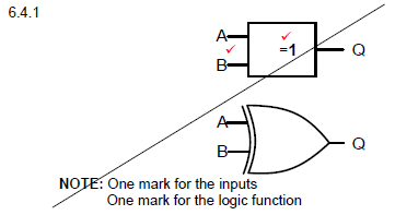
NOTE: One mark for the inputs
One mark for the logic function (2)
NOTE: See examination instruction
6.4.2
- 0✓
- 1 ✓
- 1 ✓
- 0 ✓ (4)
6.5 The inductive proximity sensor is applied in:
- Counting of metal objects✓
- Positioning of metal objects
- Detect the presence of metal objects and whether they are ferrous or non-ferrous. (1)
6.6
6.6.1 An ON-delay timer contact✓
Edge triggered wiping relay (Siemens) (1)
6.6.2
- When the push button (I1) is pressed, the Timer will be energised.✓
- The normally closed contact of the Timer will open ✓ (TD)
- The output (Q) will be at low state. ✓ (OFF)
- The output will remain at that off state for 15 seconds.
- When the timer TD times through it will reset to low. ✓
- Contacts TD will close (inverted input) and Q will go high until the timer TD is set via I1 again. ✓ (5)
6.7 The circuit will not latch ✓ when the start button is released. (1)
6.8
6.8.1 The "Red Lamp" will be ON ✓
The "Green Lamp will be OFF ✓ (2)
6.8.2 The function of the MC (contactor coil) is to close ✓ and open✓the contacts the moment it is energised. (i.e. MC/NO1 and MC/NO2 will close and MC/NC1 will open)
OR
The purpose of MC (contactor coil) is to magnetise the core which is connected to the contacts. When the core moves the contacts are closed.
When the coil is no longer magnetised, a coil spring opens the contacts again. (2)
6.8.3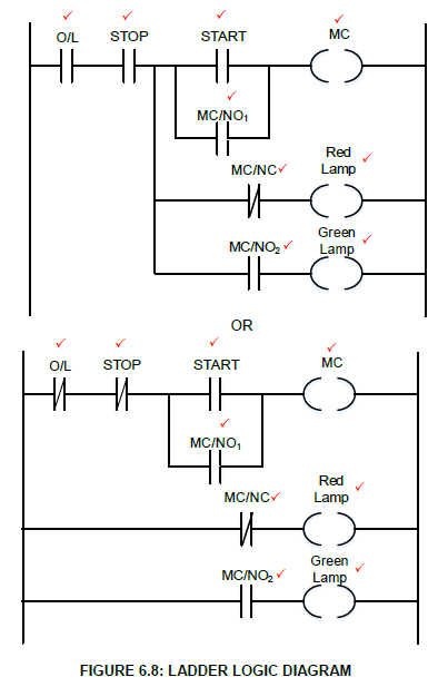
(9)
6.9
- When a three-phase AC is applied to the input unit, the diode bridge rectifying ✓ circuit convert AC to DC.
- The DC waveforms contains ripple voltage, ✓
- DC with ripple voltages are smoothed✓ by filter capacitors
- DC voltages are then converted back [by Insulated Gate Bipolar Transistor (IGBT)] into variable AC voltage ✓ and
- Variable frequency ✓ through the switching circuits will result in variable speed control.
NOTE: If the following response is given, 2 marks will be awarded.
When a three-phase or single-phase supply is connected to a VSD, its circuitry will increase or decrease the frequency of the output AC power signal supplied to the motor. (5)
6.10 Synchronous motor with a permanent magnet stator. ✓
Synchronous motor with brushes or brushless.✓ (2)
6.11
6.11.1 Pulse A ✓ has shorter on time and Pulse B ✓ has longer on time. (2)
6.11.2 The greater the width of the pulses ✓ the higher ✓ the average voltage. (2)
6.12
- The installation of the system should be done by a qualified, experienced technician. ✓
- Avoid using long cable runaways to reduce losses. ✓
- An energy efficient motor should be considered.✓
- Harmonics should be kept to a minimum.
- Consider the installation safety instructions. (3)
6.13
6.13.1 Braking Unit ✓ (1)
6.13.2 Braking resistor ✓ (1)
6.14
- When the load goes down, the motor holds back the downwards acceleration, ✓thus
- Creating excess energy✓ through induction
- This energy will be fed back to the system to be stored or dissipated as heat at the breaking resistor if excessive. ✓ (3)
[60]
TOTAL: 200