ELECTRICAL TECHNOLOGY (POWER SYSTEMS) GRADE 12 QUESTIONS - NSC EXAMS PAST PAPERS AND MEMOS NOVEMBER 2020
Share via Whatsapp Join our WhatsApp Group Join our Telegram GroupELECTRICAL TECHNOLOGY: POWER SYSTEMS
GRADE 12
NOVEMBER 2020
NATIONAL SENIOR CERTIFICATE
INSTRUCTIONS AND INFORMATION
- This question paper consists of FIVE questions.
- Answer ALL the questions.
- Answer QUESTIONS 2.3.2, 2.4.2, 2.6.2, 2.8.2, 2.8.3, 4.4, 4.5, 4.8.1, 4.8.2, 4.11.1 and 5.10 on the attached ANSWER SHEETS.
- Write your CENTRE NUMBER and EXAMINATION NUMBER on every ANSWER SHEET and staple them to your ANSWER BOOK, whether you have used them or not.
- Sketches and diagrams must be large, neat and FULLY LABELLED.
- Show ALL calculations and round off answers correctly to TWO decimal places.
- Number the answers correctly according to the numbering system used in this question paper.
- You may use a non-programmable calculator.
- Calculations must include:
9.1 Formulae and manipulations where needed
9.2 Correct replacement of values
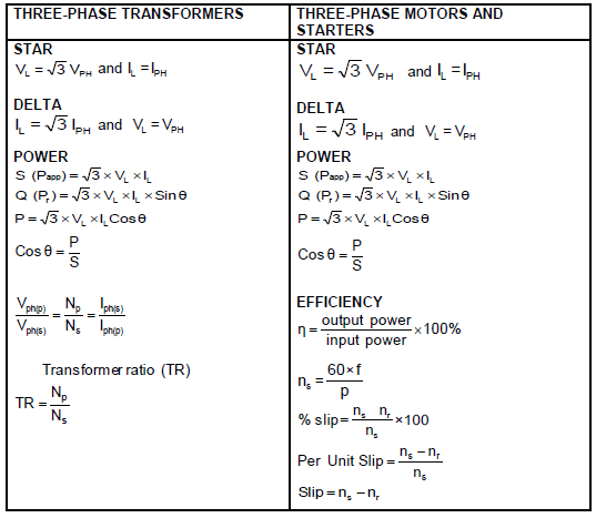
9.3 Correct answers and relevant units where applicable - A formula sheet is attached at the end of this question paper.
- Write neatly and legibly.
QUESTION 1: OCCUPATIONAL HEALTH AND SAFETY
1.1 Define health and safety equipment. (2)
1.2 Name ONE human right in the workplace. (1)
1.3 Name TWO incidents that should be reported to inspectors at the workplace. (2)
1.4 State THREE types of victimisation by an employer that are forbidden. (3)
1.5 Describe how the master switch in a workshop contributes to safety. (2)
[10]
QUESTION 2: RLC CIRCUITS
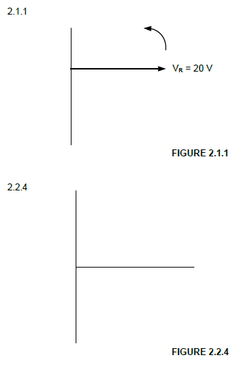
2.1 Two AC voltages, VR and VX, each have maximum values of VR = 20 V and VX = 30 V respectively.
2.1.1 Draw the phasor diagram (NOT to scale) on the ANSWER SHEET for QUESTION 2.1.1 if VX lags VR by 35°. (2)
2.1.2 Explain whether the voltages represent an RL circuit or an RC circuit. (2)
2.2 The RLC series circuit in FIGURE 2.2 below consists of a resistor of 15 Ω, an inductance of 20 mH and a capacitive reactance of 25 Ω. The components are all connected in series across a 150 V/60 Hz AC supply. Answer the questions that follow.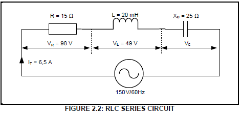
Given:
R = 15 Ω
L = 20 mH
XC = 25 Ω
VT = 150 V
f = 6 0 H z
IT = 6,5 A
2.2.1 Calculate the inductive reactance of the inductor. (3)
2.2.2 Calculate the voltage drop across the capacitor. (3)
2.2.3 Indicate whether the supply voltage is lagging or leading. Motivate your answer. (2)
2.2.4 Draw the phasor diagram of the circuit on the ANSWER SHEET for QUESTION 2.2.4. (5)
2.3 Refer to FIGURE 2.3 below and answer the questions that follow.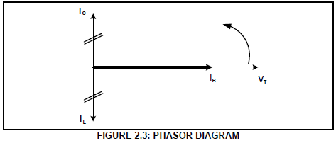
2.3.1 Identify the phasor diagram in FIGURE 2.3. (2)
2.3.2 State why the supply voltage is used as the reference in the phasor diagram. (1)
2.3.3 Explain the relationship between the total current and the impedance in a parallel resonant circuit. (2)
2.4 Refer to FIGURE 2.4 below and answer the questions that follow.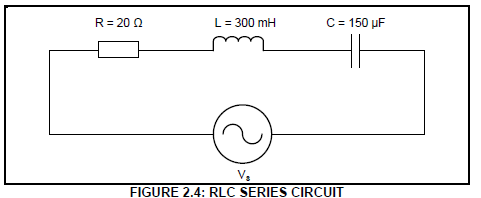
Given:
R = 20 Ω
L = 300 mH
C = 150 μF
2.4.1 Calculate the resonant frequency. (3)
2.4.2 Calculate the quality factor of the circuit. (3)
2.4.3 Determine the impedance of the circuit at resonance. Motivate your answer. (2)
2.4.4 Calculate the value of the capacitance required for the circuit in FIGURE 2.4 to resonate at 2 kHz. (3)
2.5 FIGURE 2.5 below shows the Q-factor characteristic curve of an RLC circuit, NOT to scale. Q1, Q2 and Q3 indicate how a change in the L/C ratio affects the Q-factor of a resonant circuit. Answer the questions that follow.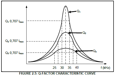
2.5.1 Identify the curve with the highest selectivity. (1)
2.5.2 Calculate the resonant frequency for response curve Q1. (3)
2.5.3 Calculate the quality factor for Q1. (3)
[40]
QUESTION 3: THREE-PHASE AC GENERATION (SPECIFIC)
3.1 Define the following terms:
3.1.1 Reactive power (2)
3.1.2 Efficiency (2)
3.2 Calculate the value of the phase voltage in a star-connected three-phase system if the line voltage is 380 V. (3)
3.3 With reference to power factor:
3.3.1 Explain the effects a low power factor will have on a system. (4)
3.3.2 List THREE methods to improve the power factor of a resistive inductive load in an AC system. (3)
3.4 Name the instrument that is used to measure electrical power over a certain period of time. (1)
3.5 A delta-connected generator delivers power to a star-connected inductive load. The phase current of the generator is 30 A and the line voltage is 380 V.
The power factor is 0,9 lagging.
Given:
VL = 380 V
PH I
= 30 A
Cos θ
= 0,9
Calculate the:
3.5.1 Line current delivered by the generator (3)
3.5.2 Impedance of each phase (5)
3.5.3 Active power generated (3)
3.6 Two wattmeters indicate 10 kW and 3 kW respectively when they are connected to measure the input power to the load. Calculate the total input power.
Given:
P1 = 10 kW
P2 = 3 kW (3)
3.7 Name ONE application of a wattmeter in three-phase AC systems. (1)
[30]
QUESTION 4: THREE-PHASE TRANSFORMERS
4.1 Explain the purpose of a step-up transformer. (2)
4.2 List THREE factors that may contribute to excessive heating in a three-phase oil-immersed transformer. (3)
4.3 Name TWO cooling methods used for oil-immersed transformers. (2)
4.4 Explain the consequences of transformer cooling failure. (2)
4.5 Explain what effect an increase in the load will have on the primary current of a transformer. (2)
4.6 The primary and secondary windings of a three-phase transformer can be connected in different ways to form a single unit. Name TWO ways. (2)
4.7 Name TWO electrical protective devices used in three-phase transformers. (2)
4.8 Illustrate, by means of a labelled diagram, the construction of a core-type three-phase transformer. Also show the magnetic couplings. (3)
4.9 Name ONE safety measure to consider when working with an energised three-phase transformer. (1)
4.10 Refer to the circuit diagram in FIGURE 4.10 below and answer the questions that follow.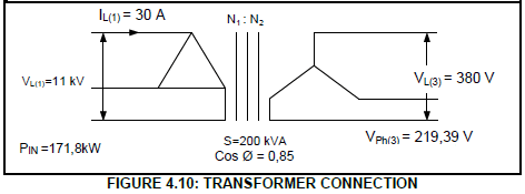
Given:
S = 200 kVA
VL(1) = 11 kV
VL(3) = 380 V
IL(1) = 30 A
PIN = 171,8kW
Calculate the:
4.10.1 Efficiency of the transformer if it operates at a power factor of 0,85 lagging. (5)
4.10.2 Turns ratio (3)
4.10.3 Secondary line current of the transformer (3)
[30]
QUESTION 5: THREE-PHASE MOTORS AND STARTERS
5.1 State THREE mechanical inspections to be conducted on a three-phase motor after installation, but before commissioning. (3)
5.2 State THREE advantages of a squirrel-cage induction motor. (3)
5.3 Study FIGURE 5.3 below and answer the questions that follow.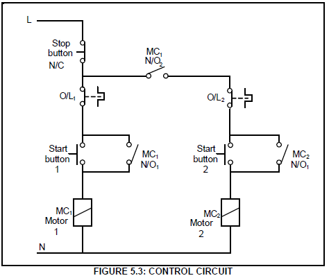
5.3.1 Identify the control circuit in FIGURE 5.3. (1)
5.3.2 Explain the function of the following components in FIGURE 5.3:
- Stop button (2)
- MC1 (N/O1) (3)
5.3.3 Describe the starting sequence of the control circuit. (6)
5.4 A three-phase induction motor with 6 pole pairs per phase is connected to a 380 V/50 Hz supply and has a slip of 0,05 units.
Given:
p = 6
f = 50 Hz
s = 0,05 units
V = 380 V
Calculate the:
5.4.1 Synchronous speed (3)
5.4.2 Rotor speed (3)
5.5 An 18 kW three-phase motor is connected in delta to a 380 V/50 Hz supply. The power factor is 0,8.
Given:
VL = 380 V
f = 50 Hz
P = 18 kW
Cos θ = 0,8
Calculate the:
5.5.1 Line current drawn from the supply (3)
5.5.2 Apparent power of the motor (3)
[30]
QUESTION 6: PROGRAMMABLE LOGIC CONTROLLERS (PLCs)
6.1 Describe the following terms with reference to PLCs:
6.1.1 Hardware (2)
6.1.2 Software (3)
6.1.3 Opto-coupler (3)
6.2 List THREE important hardware components of a PLC. (3)
6.3 State THREE safety precautions to be considered when connecting a PLC to the supply. (3)
6.4 FIGURE 6.4 below shows a ladder logic circuit. Answer the questions that follow.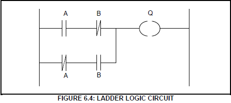
6.4.1 Draw the logic gate symbol of the ladder logic circuit in FIGURE 6.4. (2)
6.4.2 Complete the truth table in FIGURE 6.4.2 below by writing ONLY the state of the output on the ANSWER SHEET for QUESTION 6.4.2.
| INPUT A | INPUT B | OUTPUT Q |
| 0 | 0 | (a) |
| 0 | 1 | (b) |
| 1 | 0 | (c) |
| 1 | 1 | (d) |
(4)
6.5 State ONE application of an inductive proximity sensor. (1)
6.6 FIGURE 6.6 below shows a PLC logic program with a time delay of 15 seconds. Answer the questions that follow.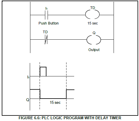
6.6.1 State whether the logic program represents an ON-delay timer contact or an OFF-delay timer contact. (1)
6.6.2 Describe the sequential operation of the logic program when the push button (I1) is pressed. (5)
6.7 The circuit in FIGURE 6.7 below is programmed with a fault, as shown between points A and B. Explain the effect that the fault will have on the operation of the circuit.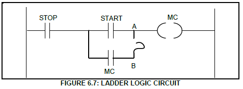
6.8 Refer to the control circuit in FIGURE 6.8 below and answer the questions that follow.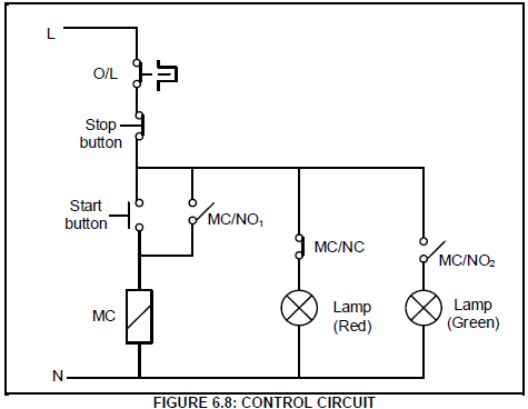
6.8.1 State the conditions of the red lamp and the green lamp before the start button is pressed. (2)
6.8.2 Explain the function of MC in the circuit. (2)
6.8.3 Draw a ladder logic diagram that will execute the same function as the control circuit in FIGURE 6.8. (9)
6.9 Explain the principle of operation of the variable speed drive (VSD). (5)
6.10 Name the TWO types of synchronous AC motors used with VSDs. (2)
6.11 Refer to the VSD output voltage pulses in FIGURE 6.11 below, and answer the questions that follow.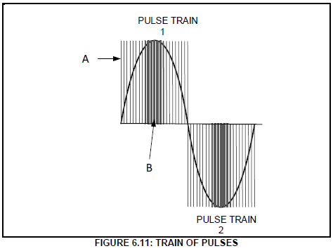
6.11.1 Describe the duration of the switching time at area A and area B with reference to pulse width modulation in FIGURE 6.11. (2)
6.11.2 State the effects the width of the pulses has on the average output voltage in FIGURE 6.11 A. (2)
6.12 State THREE precautions that must be considered when working with a VSD. (3)
6.13 Refer to FIGURE 6.13 below and answer the questions that follow.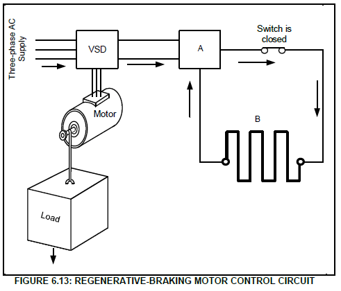
Identify component:
6.13.1 A (1)
6.13.2 B (1)
6.14 Explain what will happen to the energy generated by the motor in FIGURE 6.13 when the load moves down. (3)
[60]
TOTAL: 200
FORMULA SHEET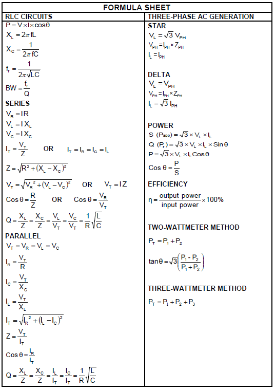
QUESTION 2: RLC CIRCUITS