MECHANICAL TECHNOLOGY(AUTOMOTIVE) GRADE 12 MEMORANDUM - NSC EXAMS PAST PAPERS AND MEMOS MAY/JUNE 2021
Share via Whatsapp Join our WhatsApp Group Join our Telegram GroupMECHANICAL TECHNOLOGY: AUTOMOTIVE
GRADE 12
NATIONAL SENIOR CERTIFICATE EXAMINATION
MEMORANDUM
MAY/JUNE 2021
QUESTION 1: MULTIPLE-CHOICE QUESTIONS (GENERIC)
1.1 B ✓(1)
1.2 A ✓ (1)
1.3 C ✓ (1)
1.4 C ✓(1)
1.5 D✓ (1)
1.6 A ✓ (1)
[6]
QUESTION 2: SAFETY (GENERIC)
2.1 First aid basic treatment:
- Examination ✓
- Diagnosis ✓
- Treatment ✓ (3)
2.2 Drill press (Already been switched on):
- Never leave the drill unattended while in motion.✓
- Switch off the drill when leaving. ✓
- Use a brush or wooden rod to remove chips. ✓
- When reaching around a revolving drill, be careful that your clothes do not get caught in the drill or drill chuck. ✓
- Don't stop a revolving chuck with your hand. ✓
- Don't adjust the drill while working. ✓
- Don't open any guard while in motion. ✓
- Keep hands away from action points. ✓
- Do not force the drill bit into the material.✓
- Apply cutting fluid if required. ✓
(Any 2 x 1) (2)
2.3 Isolation of electrode holder:
To prevent electric shock. ✓ (1)
2.4 Disadvantages of the process layout:
- Production is not always continuous. ✓
- Transportation costs between process departments may be high. ✓
- Additional time is spent in testing and sorting as the product moves to the different departments. ✓
- Damage to fragile goods may result from extra handling. ✓
(Any 2 x 1) (2)
2.5 Advantages of the product layout:
- Handling of material is limited to a minimum.✓
- Time period of manufacturing cycle is less. ✓
- Production control is almost automatic. ✓
- Control over operations is easier. ✓
- Greater use of unskilled labour is possible. ✓
- Less total inspection is required. ✓
- Less total floor space is needed per unit of production. ✓
(Any 2 x 1) (2)
[10]
QUESTION 3: MATERIALS (GENERIC)
3.1 Heat-treatment:
- Heat the metal slowly to a certain temperature. ✓
- Soak the metal for a certain period to ensure a uniform temperature. ✓
- Cool the metal at a certain rate to room temperature. ✓ (3)
3.2 Quenching mediums:
- Water ✓
- Brine✓
- Liquid salts ✓
- Oil ✓
- Soluble oil and water ✓
- Sand ✓
- Molten lead ✓
- Air ✓
- Lime ✓
(Any 3 x 1) (3)
3.3 Annealing:
- To relieve internal stresses of the steel ✓
- Soften steel to make machining possible ✓
- Make steel ductile ✓
- Refine grain structure ✓
- Reduce brittleness ✓
(Any 1 x 1) (1)
3.4 Carbon steels:
- Low carbon steel ✓
- Medium carbon steel ✓
- High carbon steel ✓ (3)
3.5 Iron-carbon equilibrium diagram:
- Percentage carbon / carbon content ✓
- Temperature in °C ✓
- AC3 line / Higher critical temperature ✓
- AC1 line / Lower critical temperature ✓ (4)
[14]
QUESTION 4: MULTIPLE-CHOICE QUESTIONS (SPECIFIC)
4.1 C ✓(1)
4.2 C ✓(1)
4.3 D ✓(1)
4.4 B✓(1)
4.5 C ✓(1)
4.6 C✓(1)
4.7 B✓(1)
4.8 A ✓(1)
4.9 C ✓(1)
4.10 A ✓(1)
4.11 A ✓(1)
4.12 D✓(1)
4.13 C ✓(1)
4.14 D ✓(1)
[14]
QUESTION 5: TOOLS AND EQUIPMENT (SPECIFIC)
5.1 Compression tester labels:
- Pressure gauge/Pressure meter ✓
- Pressure release valve ✓
- Air hose/Pipe/Flexible pipe ✓
- Spark plug connector/Adapter ✓(4)
5.2 Function of Cylinder Leakage Tester:
- To check where the combustion chamber/cylinder leaks gases ✓ during compression stroke/power stroke. ✓
- To determine the percentage ✓ pressure loss ✓ from the combustion chamber.
(Any 1 x 2) (2)
5.3 Cylinder leakage test procedure:
- Turn the crank shaft until both valves, on the cylinder to be tested, are closed. ✓
- Remove the HT leads / spark plugs ✓
- Connect the spark plug adaptor (tester) to the spark plug hole. ✓
- Lock the crankshaft pulley so that it cannot turn. ✓
- Couple the compressed air pipe to the tester and calibrate the tester. ✓
- Couple the spark plug adapter hose to the cylinder leakage tester. ✓
- Note the results and location of gas leakage occurring in the combustion chamber. ✓
(Any 6 x 1) (6)
5.4 Exhaust gas analyser:
- Hydrocarbon (fuel and oil vapour) / HC ✓
- Carbon dioxide / CO2 ✓
- Sulphur dioxide / SO2 ✓
(Any 2 x 1) (2)
5.5 Exhaust gas analysis test precautions:
- Always calibrate the exhaust gas analyser with the pick-up hose removed. ✓
- The pick-up hose must not be stepped on or restricted in any way. ✓
- The pick-up hose connections must be airtight. ✓
- The vehicle being tested should have no leaks in the exhaust, manifolds or vacuum systems. ✓
- Must be conducted in a well-ventilated area.✓
- Take good care when handling the equipment. ✓
(Any 3 x 1) (3)
5.6 Function of Turn-tables:
To make it possible ✓ to turn the front wheels in and out / side to side ✓ when checking the wheel alignment angles. (2)
5.7 Use of optical alignment gauge:
To measure / check the toe-in and toe-out of the vehicle. ✓ (1)
5.8 Functions of OBD scanner:
- Scan for faults (diagnostics). ✓
- Programme the ECU. ✓
- Reset fault codes. ✓
- Programme the keys to vehicle's ignition system. ✓
(Any 3 x 1) (3)
[23]
QUESTION 6: ENGINES (SPECIFIC)
6.1 Correcting static imbalance:
- By fitting balance mass pieces to the crank webs. ✓
- By removing metal from the crank webs. ✓
- By arranging the crank pins of the crankshaft. ✓
(Any 2 x 1) (2)
6.2 Crankshaft balancing:
6.2.1 Dynamic balancing:
Balancing in all directions✓ while crankshaft is rotating. ✓ (2)
6.2.2 Reciprocating mass:
The mass of the pistons, gudgeon pins ✓ and the upper third of the connecting rod. ✓(2)
6.3 Features to improve engine balance:
- Connecting rods and pistons are kept as light as possible / static balanced. ✓
- Flywheel is carefully balanced. ✓
- Counterweights on the crankshaft. ✓
- The firing order is reconfigured. ✓ (4)
6.4 Types of vibration dampers:
- Friction face-type ✓
- Combined rubber and friction disc ✓
- Rubber type ✓
- Inertia ring type ✓
(Any 2 x 1) (2)
6.5 Different types of cylinder arrangements:
- Inline type / Straight arrangement ✓
- V-type ✓
- W-type / double-V type ✓(3)
6.6 Three-cylinder inline engine: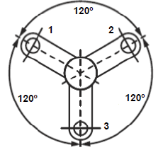
Marking:
Labelling power impulse angle 120°. ✓
Drawing position of crankpins. ✓
Numbering of crankpins. ✓ (3)
6.7 Types of superchargers:
- Roots ✓
- Twin-screw ✓
- Centrifugal and ✓
- Vane ✓
(Any 3 x 1) (3)
6.8 Advantages of using a turbocharger:
- More power is obtained from an engine with the same engine capacity. ✓
- A turbocharger is driven by the exhaust gases of the engine and therefore there is no power loss✓
- It gives improved fuel consumption in proportion to engine capacity. ✓
- The effect of height above sea level on power is eliminated.✓
- Improve volumetric efficiency. ✓
(Any 3 x 1) (3)
6.9 Turbocharger:
- Intercooler/air cooler ✓
- Compressed air flow ✓
- Turbine/Turbine housing/Turbocharger ✓
- Exhaust gas flow/exhaust system/exhaust manifold✓ (4)
[28]
QUESTION 7: FORCES (SPECIFIC)
7.1 Terms:
7.1.1 Power:
Power is the rate ✓ at which work is done. ✓
7.1.2 Compression Ratio:
It is the ratio between the total volume of a cylinder when the piston is at bottom dead centre (BDC) ✓ to the volume in a cylinder when the piston is at top dead centre (TDC).✓ (2)
7.2 Calculation of compression ratio:
7.2.1 Swept volume:= πD2 x L
4
π72 x 7.5
4
SV = 288,63 cm
7,2.2 Original clearance volume:
CV = SV
CR - 1
= 288.63
9.5 - 1
=288.63
8.5
CV = 33,96 cm
7.2.3 New bore diameter:
Compression ratio = SV +CV
CV
= SV + 1
CV
SV = CV(CR 1)
= 33,96(10 - 1)
SV = 305,64 cm3
SV =πD2 x L
4
Diameter =√SV x 4
π x L
D = 305,64 4
π x 7,5
D = 7,203 cm
D = 72,03 mm (6)
7.3 Power calculations:
7.3.1 Torque:
Torque = Force x Radius
= (25 x 10) x 420
1000
= 250 x 0,42
= 105 N.m
7.3.2 Indicated power:
P = 900kPa = 900 x 103Pa
L = 86mm = 86 = 0.086m
1000
D = 84mm
= 84 = 0,084m
1000
A = π x D2
4
= π x 0.0842
4
= 5,54 x 10⁻³ m2
OR
A = π x D2
4
= π x 842
4
= 5541,77mm2
=5541,77 x 10-6m2
N = 2000r/min = 2000 = 16,667 power stroke/sec
60 x 2
n = 4 cylinders
IP = PLANn
= (900 x 103) x 0,086 x 5541,77 x 10-6 x 16,667 x 4
= 28596W
= 28,60 kW
OR
N = 2000r/min =2000= 33,333 r/sec
60
n = 4/2 = 2 power strokes
IP = PLANn
= (900 x 103) x 0,086 x 5541,77 x 10-6 x 33.333 x 2
= 28600W
= 28,60 kW (8)
7.3.3 Brake power:
Brake Power = 2πNT
= 2 x π x 2000 x 105
60
= 21991,149 W
= 21,99 kW (3)
7.3.4 Mechanical efficiency:
Mechanical efficiency = BP x 100
IP
= 21.99 x 100
28.60
= 76.89%
(NO UNIT, NO MARK FOR FINAL ANSWER) (2)
[32]
QUESTION 8: MAINTENANCE (SPECIFIC)
8.1 Cooling system pressure test:
8.1.1 Repair or replace water hose or clamp. ✓(1)
8.1.2 Cylinder head gasket blown. / Cylinder head warped. ✓(1)
8.1.3 Replace Welch or core plug. ✓(1)
8.1.4 Replace radiator cap with suitable replacement. ✓(1)
8.2 Function of the radiator cap:
- Regulates the pressure in the cooling system. ✓
- Allows coolant to return to the radiator from the expansion tank. ✓
- The radiator cap seals / close the cooling system. ✓
(Any 2 x 1) (2)
8.3 Exhaust gas readings causes:
8.3.1 Possible causes of high carbon monoxide (CO) reading:
- Too rich mixture ✓
- Ignition misfire✓
- Dirty or restricted air filter ✓
- Improper operation of the fuel delivery system. ✓
- Faulty thermostat / stuck in open position or coolant sensor ✓
- Non-functioning PCV valve system ✓
- Catalytic converter not working ✓
(Any 2 x 1) (2)
8.3.2 Possible causes high nitrogen oxide (NOx) reading:
- Lean fuel mixture ✓
- Improper spark advance ✓
- Malfunctioning EGR valve ✓
- Malfunctioning catalytic converter ✓
(Any 2 x 1) (2)
8.3.3 Possible causes high oxygen (O2) reading:
- Too lean air-fuel ratio ✓
- Ignition problems ✓
- Vacuum leaks✓
- Malfunctioning catalytic converter ✓
(Any 2 x 1) (2)
8.4 Safety requirements when setting up the oil tester:
- Ensure the tester can read the expected pressures of the engine. ✓
- Clean the sender unit area before fitting the tester. ✓
- Ensure that the rubber hoses of the tester are not perished.✓
- Keep the tester away from moving engine parts when conducting the test.✓
(Any 3 x 1) (3)
8.5 Fuel-pressure test/manufacturers' specifications:
- Fuel pressure (suction) before the fuel pump. ✓
- Fuel pump delivery pressure (after the fuel pump). ✓
- Fuel-line pressure at idle speed. ✓
- Fuel-line pressure at high revolutions. ✓
- Fuel pressure in the common rail (at injectors). ✓
(Any 4 x 1) (4)
8.6 Compression test:
8.6.1 High tension leads:
- The ignition system will be disabled. ✓
- Prevent electrical shock✓
- To have access to the spark plugs in order to remove them. ✓
(Any 1 x 1) (1)
8.6.2 Throttle valve fully open:
- To ensure maximum amount of air enters the cylinder.✓
- To obtain a correct reading.✓
(Any 1 x 1) (1)
8.6.3 Recording the readings:
- Compared to the specifications reading.✓
- To note the differences in readings between the cylinders.✓
(Any 1 x 1) (1)
8.7 Increase in compression after wet test:
- Piston ring / Compression ring✓
- Cylinder (sleeve / walls)✓
(Any 1 x 1) (1)
[23]
QUESTION 9: SYSTEMS AND CONTROL (AUTOMATIC GEARBOX) (SPECIFIC)
9.1 Differences between an automatic gearbox and a manual gearbox:
- Manual – clutch pedal operated.✓
Automatic – no clutch pedal operated. ✓ - Manual – Gears selected manually with gear lever. ✓
Automatic – Gears selected automatically by the gearbox. ✓
(Any 1 x 2) (2)
9.2 Function of torque converter:
- Multiplies engine torque automatically according to road and engine speeds✓
- Transfers drive from the engine to the transmission. ✓
- Acts as a Flywheel to keep the engine turning during the idle strokes.✓
- Slips during initial acceleration and while stopping to prevent stalling.✓
- Dampens torsional vibrations of the engine✓
- Drives the Transmission oil pump.✓
(Any 2 x 1) (2)
9.3 Lockup clutch:
To overcome slip✓ that occurs inside the torque converter. ✓ (2)
9.4 Stall speed:
- The condition when the impeller of a torque converter rotates at maximum speed ✓ and the turbine is almost stationary.✓
- When the pump has reached the highest velocity ✓ and the turbine is at stall (standing still). ✓
- When the vehicle is stationary✓ just before it starts moving / while the engine is idling. ✓
(Any 1 x 2) (2)
9.5 Single epicyclic gear system:
9.5.1 Epicyclic gear train:
- Sun gear✓
- Annulus / Ring gear ✓
- Planet gear ✓
- Planet carrier ✓ (4)
9.5.2 Advantages of an epicyclic gear train:
- The input shaft and output shaft have the same axis of rotation. ✓
- Load is distributed to several planetary gears.✓
- Many transmission-ratio options from ONE or a combination of several gear trains.✓
- Longer service life compared to traditional gearboxes for similar load. ✓
- Epicyclic gearbox has the ability to transmit higher torque. ✓
- It has less inertia. ✓
- Used to obtain higher gear ratios.✓
- Compact in size.
- All the gears are constantly in mesh. ✓
(Any 2 x 1) (2)
9.6 Function of the valve body:
- It detects the load ✓ and adjust the gear ratio according to the torque requirements.✓
- It directs the oil pressure ✓ to the correct hydraulic actuator. ✓
(Any 1 x 2) (2)
9.7 Methods of cooling the automatic transmission oil:
- By using a special oil cooler alongside the engine cooling radiator ✓ and circulating transmission fluid through it. ✓
- Circulating transmission fluid ✓ through a radiator✓
- The transmission oil sump ✓ is designed with fins to assist with cooling. ✓
(Any 1 x 2) (2)
[18]
QUESTION 10:SYSTEMS AND CONTROL (AXLES, STEERING GEOMETRY AND ELECTRICITY) (SPECIFIC)
10.1 Requirements of a well-planned steering mechanism:
It must be …
- light and easy to control. ✓
- free from vibration and road shocks.✓
- as direct as possible without needing too much driver attention or effort.✓
- self-centring. ✓
- able to operate without being unduly affected by the action of the suspension or braking systems.✓
(Any 3 x 1) (3)
10.2 Wheel alignment angles:
10.2.1 Function of Positive camber:
- Less steering effort ✓
- The vehicle mass being carried by the larger inner front wheel bearing. ✓
(Any 1 x 1) (1)
10.2.2 Function of Ackermann's angle:
It allows for variable toe-out to the front wheels on turns. ✓(1)
10.3 Caster:
10.3.1 Wheel alignment angle: C
Negative ✓ caster ✓angle (2)
10.3.2 Negative caster angle purpose:
Negative caster ensures easier turning ✓ and provides better cornering to the vehicle. ✓ (2)
10.3.3 Caster angle labels:
A. King pin / Steering axis ✓
B. Perpendicular line ✓
D. Centre line of kingpin / Steering axis ✓ (3)
10.4 Engine management system:
10.4.1 Function of sensor:
- It detects the engine operating conditions. ✓✓
- It gives the input information to the ECU. ✓✓
(Any 1 x 2) (2)
10.4.2 Function of actuators:
- It gets the output information / signal from the ECU.✓✓
- It makes the necessary adjustments. ✓✓
(Any 1 x 2) (2)
10.5 Requirements to make the catalytic convertor function effectively:
- The convertor working temperature must not exceed 600 °C. ✓
- Unleaded petrol must be used. ✓
- Prevent persistent misfire. ✓
- Prevent burnt engine oil from melting the ceramic monolith. ✓
- The lambda sensor must function properly. ✓
(Any 2 x 1) (2)
10.6 Lambda sensor:
The lambda sensor is fitted on the exhaust system. (1)
10.7 Adaptive speed control:
- Maintain a speed as set by the driver.✓
- Adapt the speed to maintain a safe distance from the vehicle in front. ✓
- Provide a warning if there is a risk of a collision. ✓
- Prevent driver fatigue. ✓
- Improve fuel economy. ✓
- A constant controlled speed setting prevents speeding fines. ✓
(Any 3 x 1) (3)
10.8 Diode:
10.8.1 Diode ✓ (1)
10.8.2 Function of the diode:
- The function of the diode is used to change alternating current ✓ into direct current. ✓
- It allows the current flow in the circuit in one direction only ✓ and blocks it from flowing in the opposite direction. ✓
(Any 1 x 2) (2)
10.9 Function of components in the alternator:
10.9.1 Rectifier:
Converts alternating current (AC) to direct current (DC). ✓ (1)
10.9.2 Stator:
- To provide a core ✓that concentrates the magnetic lines of force onto the stator windings. ✓
- To provide a coil ✓ into which a voltage is induced which is used to charge the battery.✓
- Converts the rotating magnetic field ✓ to electric current to charge the battery.✓
(Any 1 x 2) (2)
10.9.3 Rotor:
- Provides a rotating ✓ electro-magnet. ✓
- Induces an electric voltage ✓ into the stator windings. ✓
- Fitted with slip rings ✓ to allow for a moving electrical connection. ✓
(Any 1 x 2) (2)
10.10 Functions of the check valve in the electric fuel pump:
- It ensures the pressure in the fuel line is maintained. ✓
- It allows the fuel to flow in one direction only from the fuel tank.✓ (2)
[32]
TOTAL:200