Mechanical Technology: Automotive Grade 12 Memorandum - NSC Past Papers And Memos September 2020 Preparatory Examinations
Share via Whatsapp Join our WhatsApp Group Join our Telegram GroupMEMORANDUM
QUESTION 1: MULTIPLE-CHOICE QUESTIONS (GENERIC)
1.1 C (1)
1.2 B (1)
1.3 C (1)
1.4 A (1)
1.5 B (1)
1.6 C (1) [6]
QUESTION 2: SAFETY (GENERIC)
2.1 Gas welding (PPE)
- Eye protection
- Overall / leather apron
- Safety boots
- Gloves (Any 2 x 1) (2)
2.2 Safety rules that must be followed whilst the surface grinder is in operation:
- Make sure that the sparks are of no danger to co-workers.
- Do not force the material onto the grinding wheel.
- Do not plunge grind.
- Bring the material slowly into contact with the grinding wheel.
- Never clean or adjust the machine whilst it is in motion.
- Use cutting fluid.
- Know where the emergency stop is located.
- Stop the machine before any adjustment.
- Keep tools clear from moving parts.
(Any 2 x 1) (2)
2.3Completing a task on any machine:
- Switch the machine off. (1)
2.4 TWO safety measures to observe before switching the angle grinder on:
- Make sure that there are no cracks or chips on the disc.
- Make sure that the emery disc that is fitted is rated above the revolutions at which it is turned by the motor.
- Make sure that the space between the tool rest and the emery disc does not exceed 3 mm.
- Ensure that guards are in place.
- Do not stand in front of the machine when switching it on; wait until it reaches its full speed.
- Do not force or bump the work piece against the emery disc.
- Grind only on the front surface of the wheel, not the sides.
- All grinding machines must have a sign indicating the revolutions at which the spindle rotates. (Any 2 x 1) (2)
2.5 Importance of a welding helmet:
- To protect your eyes and face from ultra-violet rays and radiation (1)
2.6 Types of workshop layouts:
- Process layout
- Product layout (2)
[10]
QUESTION 3: MATERIALS (GENERIC)
3.1
| MATERIALS | DIFFERENT TYPES OF TESTS | ||
| Sound | Filing | Bend | |
| Cast iron | Very dull sound | Easy | Cannot bend / Snaps/breaks/ Fracturea easily |
| Mild steel | Medium metallic sound | Easy | Benda easily |
(6)
3.2 Heat treatment process:
- Is the heating and cooling of metals in their solid state so as to change their properties(1)
3.3 Hardness factors:
- Workpiece size
- Quenching rate
- Carbon content (Any 2 x 1) (2)
3.4 Heat treatment processes:
3.4.1 Tempering
- Is a process applied to steel and it relieves the strains induced during the hardening process.
- It decreases the degree of hardness
- It increases toughness
- It reduces brittleness
- It gives steel fine grain structure (Any 2 x 1) (2)
3.4.2 Annealing
- Relieves internal stress
- Softens the metal
- Makes metal ductile
- Refines the grain structure
- Reduces brittleness (Any 2 x 1) (2)
3.5 Hardness of steel depends upon
- Carbon content (1)
[14]
QUESTION 4: MULTIPLE-CHOICE QUESTIONS (SPECIFIC)
4.1 A (1)
4.2 C (1)
4.3 D (1)
4.4 B (1)
4.5 B (1)
4.6 D (1)
4.7 C (1)
4.8 D (1)
4.9 B (1)
4.10 A (1)
4.11 C (1)
4.12 D (1)
4.13 B (1)
4.14 A (1) [14]
QUESTION 5: TOOLS AND EQUIPMENT (SPECIFIC)
5.1 Bubble gauge:
5.1.1 Bubble gauge (1)
5.1.2
- A – King-pin inclination scale
- B – Caster scale
- C – Camber scale
- D – Gauge zero scale
- E – Mounting equipment on wheel (5)
5.1.3
- Caster angle
- Camber angle
- King-pin inclination (3)
5.2 Set-up procedure to read camber:
- Ensure that the wheels are in a straight ahead position.
- Mount the bubble gauge on the centre of the wheel.
- Zero the bubble gauge on the gauge zero scale.
- Take the reading on the camber scale.
- Do the same for the other wheels. (5)
5.3 Dynamic balancing of wheels:
- The plane of imbalance
- The extent of unbalanced forces
- The sense of direction of these forces (clockwise or counter clockwise / anticlockwise)
- Run-out of the tyre and wheel assembly (Any 3 x 1) (3)
5.4 Tools:
5.4.1 Turn table:
- To turn the front wheel 20° in and zero the bubble gauge and then turn the wheel 20° out to check the castor reading (2)
5.4.2 Wheel balancer:
- To balance the wheels of a vehicle for static and dynamic balance. (2)
5.4.3 Optical alignment tool:
- To check the toe-in and toe-out of a vehicle (2)
[23]
QUESTION 6: ENGINES (SPECIFIC)
6.1 Causes of vibration:
- The action of unbalance forces upon the shaft
- The twisting effects of the power stroke (2)
6.2 Types of vibration damper:
- Friction face-type
- Combined rubber and friction disc (2)
6.3 In-built engine balance features:
6.3.1 Crankshafts are carefully balanced with webs extended and drilled to form balance mass piece at points opposite the connecting rods. (2)
6.3.2 Connecting rods and pistons are kept as light as possible to reduce reciprocating forces. (2)
6.3.3 Flywheels are carefully balanced and are usually fitted to the crankshaft flange in one position only. (2)
6.4 Factors that determine engine configuration:
- Number of cylinders
- Position of cylinders
- Engine layout
- Firing order
- Engine location and mounting (Any 3 x 1) (3)
6.5 Types of engine configuration:
- In-line engine
- V-type engine
- Horizontally opposed engine (Any 2 x 1) (2)
6.6 Identification of an engine configuration:
- The crankshaft of a V-engine (1)
6.7 Factors that determine the firing order:
- The position of the crank on the crankshaft
- The arrangement of the cams on the camshaft (2)
6.8 Firing order of a 5-cylinder in-line engine:
- 12453 OR 13542 (1)
6.9 Turbocharger internal components:
- A – Turbine exhaust gas outlet
- B – Turbine wheel OR impeller
- C – Turbine exhaust gas inlet
- D – Compressor air discharge
- E – Compressor
- F – Compressor air inlet (6)
6.10 Disadvantages of a turbocharger:
- It can have lag problems.
- It tends to heat up the air, reducing density.
- Some require shut-down process.
- It requires pressure lubrication for high speed bearings.
- Its lubricant must be air cooled.
- Over-revving must be controlled by waste gate.
(Any 3 x 1) (3)
[28]
QUESTION 7: FORCES (SPECIFIC)
7.1 Compression ratio:
- The compression ratio of an internal combustion engine is the ratio of compression of the inlet charge during the compression stroke to the total volume of the cylinder. (2)
7.2 Compression ratio: Swept volume:
- ????? ?????? = ∏?2 ?
4
= ∏(9.02) × 11
4
= 700 cm3
Compression ratio = ??+??
??
= 700+70
70
11 : 1 (6)
7.3 New compression ratio:
- Swept volume = ∏(9,612) × 11
4
= 797,865 cm3
Compression ration = 797,865 + 70
70
=12,4 : 1 (4)
7.4 Methods used in raising compression ratio:
- Remove shims between the cylinder block and cylinder head.
- Fit thinner cylinder head gasket.
- Machine metal from cylinder head.
- Skim metal from cylinder block.
- Fit piston with higher crown.
- Fit crankshaft with longer stroke.
- Increase the bore of the cylinders. ( Any 4 x 1) (4)
7.5Indicated power:
- Indicated power is a measure to determine the total power developed by the burning of fuel in the combustion chamber of an internal combustion engine. (2)
7.6 Power calculations:
7.6.1 Indicated power
- = P × L × A × N × n
P = 1200000 Pa
L= 86
1000
=0,086 m
A = π?2
4
= π× 0,092
4
=6,36 × 10⁻³ m2
N = 4200
60×2
= 35 r/s
N = 4 cylinders
Indicated power = 1200000 × 0,086 × 6,36 × 10-3 × 35 × 4
= 91889,28 W
= 92 kW (7)
7.6.2
- Brake power = 2 π NT
N =4200
60
70 r/s
= 2 × π × 70 × 180
=211115,03 W
=79168,13 W
=79,2 kW (3)
7.6.3 Mechanical efficiency
- = ?? ×100%
??
= 79,2 ×100%
92
= 82,5% (2)
7.7 Term definition:
- It is the percentage energy that an engine puts out due to mechanical losses as compared to the ideal engine power. (2)
[32]
QUESTION 8: MAINTENANCE (SPECIFIC)
8.1 Reasons for high CO (carbon monoxide) reading:
8.1.1
- Too rich mixture
- Ignition misfire
- Dirty or restricted air filter
- Improper operation of the fuel delivery system
- Faulty thermostat or coolant sensor
- Non-functioning PVC valve system
- Catalytic converter not working (Any 3x1) (3)
8.1.2 Corrective measures:
- Reset fuel mixtures.
- Check for misfire and repair.
- Replace air filter.
- Check and correct fuel delivery system. (Any 3 x 1) (3)
8.1.3 Gases analysed:
- CO2
- SO2
- NO
- HC
- O2 (Any 3 x 1) (3)
8.2 Cylinder leakage testing:
- Wet test (1)
8.3 Cylinder leakage and causes:
8.3.1 Leakage inlet valve (1)
8.3.2 Blown cylinder head gasket or cracked cylinder block (1)
8.3.3 Piston rings are worn (1)
8.4 Oil pressure testing:
- Oil pressure when the engine is idling.
- Oil pressure when the engine is cold.
- Oil pressure when the engine is hot.
- Oil pressure on high revolution. (4)
8.5 Causes of low fuel pressure reading:
- Faulty fuel pump
- Blocked or restricted fuel filter
- Cracked or restricted fuel line
- Clogged pump inlet strainer
- Low voltage to fuel pump
- Faulty fuel pressure regulator
- Faulty fuel pump relay
- Empty fuel tank (Any 3 x 1 ) (3)
8.6 Cooling system pressure testing:
- Water hoses
- Water pump
- Radiator
- Corroded core plugs
- Interior heater radiator
- Faulty radiator cap (Any 3 x 1 ) (3)
[23]
QUESTION 9: SYSTEMS AND CONTROL (AUTOMATIC GEARBOX) (SPECIFIC)
9.1 Purpose of automatic gearbox:
- To relieve the driver of clutch and gearshift operation, thereby allowing the driver to concentrate on driving the vehicle (2)
9.2 Advantages of an automatic gearbox
- It reduces driving fatigue.
- It ensures reduction of wheel spin under bad road condition.
- The vehicle can be stopped suddenly without the engine stalling
- The system puts a damper on/muffles all engine vibrations.
(Any 3 x 1) (3)
9.3 Torque converter:
9.3.1 Torque converter (1)
9.3.2 Parts
- A – One-way clutch
- B – Turbine
- C – Pump
- D – Turbine shaft
- E – Gearbox housing (5)
9.3.3 Torque converter functions:
- Transfers engine torque to the transmission.
- Multiplies the engine torque.
- Provides a direct drive from engine to transmission.
- It muffles/puts a damper on all engine vibrations.
- It acts as flywheel. (Any 3 x1 ) (3)
9.3.4 Function of parts:
- It sets the fluid in motion at high pressure to the turbine, thereby causing the turbine to rotate with great torque. (2)
9.4 Torque multiplication:
- As the car speed increases, the torque multiplication tapers off gradually. (2)
[18]
QUESTION 10: SYSTEMS AND CONTROL (AXLES, STEERING GEOMETRY AND ELECTRONICS) (SPECIFIC)
10.1 Properties of a good steering mechanism:
- Light and easy to control
- Free from vibration and road shocks
- Self-centring
- Able to operate effectively under the influence of the suspension and braking system
- It must be as direct as possible to reduce too much driver’s attention.
(Any 4 x 1) (4)
10.2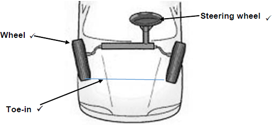 (4)
(4)
10.3 Alignments:
10.3.1 Caster angle:
- It gives self-centring action to the steering thereby keeping the wheels in straight ahead position.(2)
10.3.2 Ackermann principle:
- To avoid the need for tyres to slip sideways when following the path around a curve. (2)
10.3.3 King pin inclination:
- To bring the front wheel back to the straight ahead position after rounding a corner without any driver effort. (2)
10.4 Camber:
10.4.1 Positive camber. (2)
10.4.2
- A – Tyre
- B – Vertical line
- C – Centre line
- D – Positive camber angle
- E – Lower control arm
- F – Road surface (6)
10.4.3 Positive camber angle is the outward tilt of a front wheel away from The vehicle when viewed from the front. (1)
10.5 Factors to be taken into account before attempting alignment adjustment:
- Kerb mass must be checked against the manufacturer’s specifications
- Uneven wear on tyres
- Tyre pressure
- Run-out on wheels
- Kingpins and bushes
- Suspension ball joints for wears
- Suspension bushes for excessive free movements
- Tie-rod ends
- Sagged springs
- Ineffective shock absorbers
- Spring U-bolts
- Chassis for possible cracks
- Wheel must be balanced
- Wheel alignment specifications
- Drive shaft CV-joints (Any 5 x 1) (5)
10.6 Purpose of wheel balancing:
- To avoid shimming and bouncing of wheel assembly which can cause wearing of the steering mechanism and suspension parts. (2)
10.7 Wheel balancing:
- Static balance
- Dynamic balance (2)
[32]
TOTAL: 200