Mechanical Technology: Welding and Metalwork Grade 12 Memorandum - NSC Past Papers And Memos September 2020 Preparatory Examinations
Share via Whatsapp Join our WhatsApp Group Join our Telegram GroupMEMORANDUM
QUESTION 1: MULTIPLE-CHOICE QUESTIONS (GENERIC)
1.1 C (1)
1.2 B (1)
1.3 C (1)
1.4 A (1)
1.5 B (1)
1.6 C (1) [6]
QUESTION 2: SAFETY (GENERIC)
2.1 Gas welding (PPE)
- Eye protection
- Overall / leather apron
- Safety boots
- Gloves (Any 2 x 1) (2)
2.2 Safety rules that must be followed while the surface grinder is in operation:
- Make sure that the sparks pose no danger to co-workers.
- Do not force the material onto the grinding wheel.
- Do not plunge grind.
- Bring the material slowly into contact with the grinding wheel.
- Never clean or adjust the machine whilst it is in motion.
- Use cutting fluid.
- Know where the emergency stop is located.
- Stop machine before any adjustment
- Keep tools clear from moving parts. (Any 2 x 1) (2)
2.3 Completing a task on any machine
- Switch the machine off. (1)
2.4 TWO safety precautions before switching on the angle grinder
- Make sure that there are no cracks or chips on the disc.
- Make sure that the emery disc that is fitted is rated above the revolutions at which it is turned by the motor.
- Make sure that the space between the tool rest and the emery disc does not exceed 3 mm.
- Ensure that guards are in place
- When switching on the machine, do not stand in front of it, until it reaches its full speed.
- Do not force or bump the work piece against the emery disc.
- Grind only on the front surface of the wheel, not the sides.
- All grinding machines must have a sign indicating the revolutions at which the spindle rotates. (Any 2 x 1) (2)
2.5 Importance of a welding helmet
- To protect your eyes and face from ultra-violet rays and radiation (1)
2.6 Types of workshop layouts:
- Process layout
- Product layout (2)
[10]
QUESTION 3: MATERIALS (GENERIC)
3.1
MATERIALS | DIFFERENT TYPES OF TESTS | ||
Sound |
Filing |
Bend | |
Cast iron | Very dull sound ? | Easy ? | Cannot bend ?/ Snaps/breaks ?/ Fractures easily ? |
Mild steel | Medium metallic sound ? | Easy ? | Bends easily ? |
(6)
3.2 Heat treatment process
- Is the heating and cooling of metals in their solid state so as to change their properties. (1)
3.3 Hardness factors:
- Workpiece size
- Quenching rate
- Carbon content (Any 2 x 1) (2)
3.4 Heat treatment processes:
3.4.1 Tempering
- Is a process applied to steel and it relieves the strain induced during the hardening process.
- It decreases the degree of hardness
- It increases toughness
- It reduces brittleness
- It gives steel fine grain structure (Any 2 x 1) (2)
3.4.2 Annealing
- Relieves internal stress
- Softens the metal
- Makes metal ductile
- Refines the grain structure
- Reduces brittleness (Any 2 x 1) (2)
3.5 Hardness of steel depends upon
- Carbon content (1)
[14]
QUESTION 4: MULTIPLE-CHOICE QUESTIONS (SPECIFIC)
4.1 A (1)
4.2 D (1)
4.3 C (1)
4.4 C (1)
4.5 D (1)
4.6 B (1)
4.7 D (1)
4.8 D (1)
4.9 A (1)
4.10 A (1)
4.11 A (1)
4.12 B (1)
4.13 B (1)
4.14 A (1) [14]
QUESTION 5: TERMINOLOGY (TEMPLATES) (SPECIFIC)
5.1 Template loft: Is the heart of the structural workshop. (2)
5.2 THREE qualities of a good template loft:
- Accuracy
- Quietness
- Better lighting
- Separate from main building
- Wooden floor with black matt finish
- Large space to accommodate required work (Any 3 x 1) (3)
5.3 Web template
- Is used to mark out the positions of holes on the webs of the channel iron and girder sections. (2)
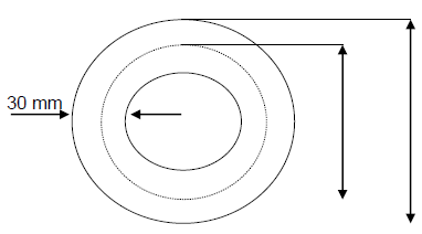
5.4 A steel ring:
5.4.1 Dimensions of the required material:
- Mean diameter = Outside diameter – Plate thickness
= 500 – 30
= 470 mm - Mean circumference = π x Mean diameter
= π x 470
=1 476,55 mm (6)
5.4.2 Make a neat sketch of the steel ring indicating the mean diameter, outside diameter and the thickness of the material:
- 1476,55 mm of 30 x 30 mm square steel bar is required to fabricate the ring.
Material thickness (4)
(4)
 (4)
(4)5.5 Fillet weld on T-joint: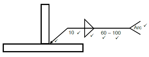 (6)
(6)
[23]
QUESTION 6: TOOLS AND EQUIPMENT (SPECIFIC)
6.1 Uses of the machines
6.1.1 Guillotine
- To cut sheet metal
- To cut plate metal (2)
6.1.2 Bench grinder
- Hand grinding-cutting tools
- Sharpening cutting tools (2)
6.1.3 Press machine
- Is used to install or remove components such as bearings or bushes in machines or mechanical devices (2)
6.2 Joining equipment labels:
6.2.1
- A – Gauges
- B – Outlet
- C – Inlet
- D – Bonnet (4)
6.2.2 Oxygen regulator (1)
6.3 Function of stock and dies:
- They are used to cut internal and external threads of the bolt and nut. (1)
6.4 Function of regulators:
- To reduce the cylinder pressure to operating or working pressure. (2)
6.5 Operating principle of plasma cutter:
- The process involves creating an electrical channel of ionised gas; that is the plasma cutter itself, through the work piece that is being cut; this forms an electric circuit back to the plasma cutter via a grounding clamp; accomplishing this via air that is blowing towards the work piece through a focused nozzle. (4)
[18]
QUESTION 7: FORCES (SPECIFIC)
7.1 Term definition
7.1.1
- Force: is an influence which changes or tends to change the state of rest of a body or motion
OR
It is often more convenient to think about a “pull” or “push”
(Any 1 x 2) (2)
7.1.2 Hooke’s law: Strain is directly proportional to the stress it caused, provided the limit of proportionality is not Exceeded. (2)
7.2 Stress and strain
7.2.1
- Area = ???
?
= ? x (0,024)2
4
= 4,525 x 10−4?2 - Stress = ?????
????
= 60 ? 103
4,525 ? 10−4
= 132,579 x 106 Pa (2)
7.2.2
- Strain = Change in length
Original length
= 0,22 X 10⁻³
212 X 10−3
= 1,038 x 10−3
= 1,04 x 10⁻³ (2)
7.2.3
- Young’s modulus of elasticity (E) = ??????
??????
= 132,58 X 10⁶
1,04 X 10−3
= 127,48 x 109
= 127,48 GPa (4)
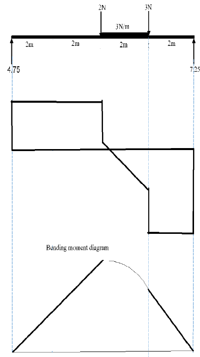
7.3 Calculations of the reactions, bending moments and shear force
7.3.1
- Moments about RL: RR X 8 = (2 x 4) + (6 x 5) + (3 x 6)
= 8 + 30 + 18
= 56
RR = 7 N - Moments about RR: RL X 8 = (3 x 2) + (6 x 3) + (2 x 4)
= 6 + 18 + 8
= 32
RL = 4 N (6)
7.3.2 The bending moments at points A, B and C.
- ??? = (4 x 4) = 16 N
??? = (4 x 6) – (2 x 2) – (6 x 1) = 14 N
??? = (4 x 7) – (2 x 3) – (6 x 2) – (3 x 1) = 7 N (3)
7.3.3 Shear forces at points, A, B and C
- SFA = 4 2 = 2
SFB = 4 – 2 – 6 = -4
SFC = 4 – 2 – 6 – 3 = -7 (3)
7.3.4 and 7.3.5
7.4
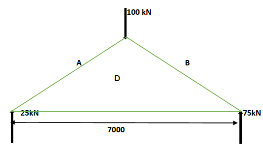
Space diagram = 1 mark
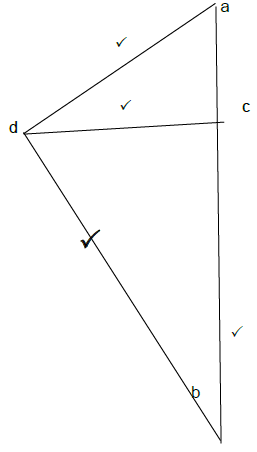
Member | Force | Nature |
AD | 29 kN ? | Strut ? |
BD | 76 kN ? | Strut ? |
CD | 14 kN ? | Tie ? |
(11) [45]
QUESTION 8: JOINING METHODS (INSPECTION WELD) (SPECIFIC)
8.1 Arc welding
- Rate of rod burning and the progress of the weld
- Amount of penetration and fusion
- The way the weld metal is flowing
- The sound of the arc, indicating correct current and voltage for the particular weld (Any 2 x 1) (2)
Oxy-acetylene
- Correct flame for the work on hand
- Correct angle of blowpipe and rod, depending on the method being used
- Depth of fusion and amount of penetration
- The rate of progress along the joint (Any 2 x 1) (2)
8.2
- HAZ (Heat-affected zone)
- Centreline cracks
- Crater cracks
- Transverse cracks (Any 2 x 2) (4)
8.3
- A – Penetration
- B – Width
- C – Height
- D – Weld bead
- E – Base metal (5)
8.4
- Shape of profile
- Uniformity
- Overlap
- Undercutting
- Penetration bead
- Root groove (Any 2 x 1) (2)
8.5
8.5.1 Spatter
- Caused by voltage being too low or amperage being too high. (2)
8.5.2 Incomplete penetration
- The weld bead does not penetrate the full depth of the weld or into the root of the weld.
- Two opposing weld beads do not inter-penetrate.
- The weld does not penetrate to the toe of a fillet weld but only bridges across it. (Any 2 x 1) (2)
8.6 Arc welding
- Rate of rod burning and the progress of the weld
- Amount of penetration and fusion
- The way the weld metal is flowing
- The sound of the arc, indicating correct current and voltage for the particular weld (Any 2 x 1) (2)
8.7 Testers
8.7.1 Nick-break test is done to:
- Determine the internal quality of the weld metal and can reveal the internal defects(2)
8.7.2 Machinability test is done to:
- Determine the hardness and strength of the welded joint.(2)
[25]
QUESTION 9: JOINING METHODS (STRESSES) (SPECIFIC)
9.1 Term definition
9.1.1 Weld distortion: Takes place in a welded joints due to uneven expansion and contractions as a result of intense heat of the arc or oxy-acetylene flame.(2)
9.1.2 Residual Stress: Is the internal stress distribution locked into the material; these stresses are present even after all external loads or forces have been removed. (2)
9.2 Factors affecting grain size
- The prior amount of cold work
- The temperature and time of the annealing process
- Composition and constitution
- Its melting point (Any 2 x 1) (2)
9.3
- Low carbon steel 0,15 – 0,30%
- Medium carbon steel 0,31 – 0,70%
- High carbon steel 0,71 – 1,5%
(Any 2 x 2) (4)
9.4 Quenching mediums
- Brine
- Water
- Oil
- Metal salt
- Air (Any 2 x 1) (2)
9.5 Factors affecting shrinkage in welding
- Size of work piece
- Weld thickness
- Thermal conductive properties of parent metal (Any 2 x 1) (2)
9.6
9.6.1 Transverse shrinkage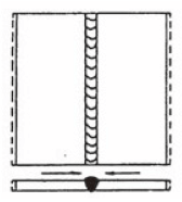 (2)
(2)
9.6.2 Longitudinal shrinkage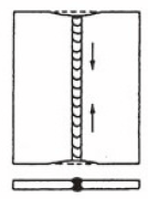 (2)
(2)
[18]
QUESTION 10: MAINTENANCE (SPECIFIC)
10.1 Keeping records assists in upholding warrantees and guarantees because service requirements inevitably form part of agreements.(1)
10.2 Due to the danger associated with a large machine, it is critical to isolate the machine completely before any maintenance is undertaken to ensure nobody can turn on the machine.(2)
10.3 Friction can be reduced by applying cutting fluid or light oil to the drill bit.(1)
10.4
10.4.1 Cutting plate of excessive thickness or hardness will overload both the blade and hydraulic system.(2)
10.4.2 The feed speed which is higher than the rate at which the power saw can cut, effectively results in the blade being forced into the materials.(2)
[8]
QUESTION 11: DEVELOPMENT (SPECIFIC)
11.1
11.1.1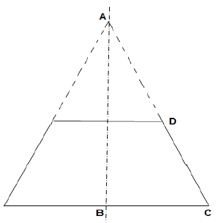
 (5)
(5)
11.1.2 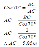 (4)
(4)
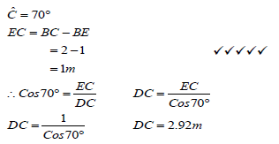
11.1.3
- Circumf . πD
π4)
= 12.57m (3)
11.2 Square-to-round transition piece:
11.2.1 The true length FG is firstly needed to draw the pattern.
- IK = 300(2units)
IH = 150(1unit)
HK =1 √3 (1unit × √3 )
The true length FG:
Plan length FG = FG - GK
= 400 - 300
=100 mm
The true FG is equalto H'F
H'F2 = H'G2 + GF2
= 8002 + 1002
H'F = √650 000
True length FG = 806 mm (5)
11.2.2 To determine the plan length CI, the sides CE and EI of triangle CEI must first be calculated.
- CE=CF-EF
= 400- 150
= 250 mm - ButEI=FH
FH = FK -HK
= 400- 259,8
=140,2mm - True length(CI)=FH2 +EI2
= 2502 +140,22
= 82156,04
= 286,63 mm (4)
[21]
TOTAL: 200