Mechanical Technology: Fitting and Machining Grade 12 Memorandum - NSC Past Papers And Memos September 2020 Preparatory Examinations
Share via Whatsapp Join our WhatsApp Group Join our Telegram GroupMEMORANDUM
QUESTION 1: MULTIPLE-CHOICE QUESTIONS (GENERIC)
1.1 C (1)
1.2 B (1)
1.3 C (1)
1.4 A (1)
1.5 B (1)
1.6 C (1) [6]
QUESTION 2: SAFETY (GENERIC)
2.1 Gas welding (PPE)
- Eye protection
- Overall / leather apron
- Safety boots
- Gloves (Any 2 x 1) (2)
2.2 Safety rules that must be followed whilst the surface grinder is in operation:
- Make sure that the sparks are of no danger to co-workers.
- Do not force the material onto the grinding wheel.
- Do not plunge grind.
- Bring the material slowly into contact with the grinding wheel.
- Never clean or adjust the machine whilst it is in motion.
- Use cutting fluid.
- Know where the emergency stop is located.
- Stop machine before any adjustment
- Keep tools clear from moving parts. (Any 2 x 1) (2)
2.3 Completing a task on any machine
- Switch the machine off. (1)
2.4 TWO safety precautions before switching the angle grinder on
- Make sure that there are no cracks or chips on the disc.
- Make sure that the emery disc that is fitted is rated above the revolutions at which it is turned by the motor.
- Make sure that the space between the tool rest and the emery disc does not exceed 3 mm.
- Ensure that guards are in place.
- When switching on the machine, do not stand in front of it, until it reaches its full speed.
- Do not force or bump the work piece against the emery disc.
- Grind only on the front surface of the wheel, not the sides.
- All grinding machines must have a sign indicating the revolutions at which the spindle rotates. (Any 2 x 1) (2)
2.5 Importance of a welding helmet
- To protect your eyes and face from ultra-violet rays and radiation (1)
2.6 Types of workshop layouts:
- Process layout
- Product layout (2)
[10]
QUESTION 3: MATERIALS (GENERIC)
3.1
MATERIALS | DIFFERENT TYPES OF TESTS | ||
Sound | Filing | Bend | |
Cast iron | Very dull sound ? | Easy ? | Cannot bend ?/ Snaps/breaks ?/ Fractures easily ? |
Mild steel | Medium metallic sound ? | Easy ? | Bends easily ? |
(6)
3.2 Heat treatment process
- Is the heating and cooling of metals in their solid state so as to change their properties (1)
3.3 Hardness factors:
- Workpiece size
- Quenching rate
- Carbon content (Any 2 x 1) (2)
3.4 Heat treatment processes:
3.4.1 Tempering
- Is a process applied to steel and it relieves the strains induced during the hardening process
- Decreases the degree of hardness
- Increases toughness
- Reduces brittleness
- Gives steel fine grain structure (Any 2 x 1) (2)
3.4.2 Annealing
- Relieves internal stress
- Softens the metal
- Makes metal ductile
- Refines the grain structure
- Reduces brittleness (Any 2 x 1) (2)
3.5 Hardness of steel depends upon
- Carbon content (1)
[14]
QUESTION 4: MULTIPLE-CHOICE QUESTIONS (SPECIFIC)
4.1 B (1)
4.2 D (1)
4.3 D (1)
4.4 A (1)
4.5 A (1)
4.6 B (1)
4.7 A (1)
4.8 B (1)
4.9 B (1)
4.10 A (1)
4.11 B (1)
4.12 B (1)
4.13 C (1)
4.14 B (1) [14]
QUESTION 5: TERMINOLOGY (LATHE AND MILLING MACHINE) (SPECIFIC)
5.1 Lathe components
5.1.1 Chuck is a lathe component used to mount and hold the workpiece at one end. (1)
5.1.2 Tool post is securely clamped to the compound slide and is used to support and fasten the cutting tool in the proper position for cutting action. (1)
5.1.3 Compound slide is situated on top of the cross slide and is used for turning operations such as taper turning and thread cutting. (1)
5.2 Milling Cutters Classes
5.2.1 Arbor cutters
- Examples: plain cutter , side cutter, staggered-tooth cutter, slitting-saw cutter, angular cutter, profile/form cutters, side-and- face cutter, helical cutter (2)
5.2.2 Shank cutters
- Examples: end mill; shell end mill; T-slot cutter and Woodruff keyseat cutter (2)
5.3 Taper-turning calculations
- Θ = 8,5° θ/2 = 4,25°
Tan θ/2 = (D – d )/ 2L
Tan 4,25 x 2 x 250 = (55-d)
d = 17,84 mm
d = 18 mm (4)
5.4 Dividing head components
- – Index plate
- – Index crank
- – Sector arms
- – Single-start worm
- ‒ Worm wheel/gear (5)
5.5 Lead calculations
- Lead = No. of starts x pitch
= 3 x 1,75 mm
= 5,25 mm (2)
[18]
QUESTION 6: TERMINOLOGY (INDEXING) (SPECIFIC)
6.1 Gear calculations:
6.1.1 Dividing head: it breaks up the circumference of a circular workpiece into a number of equal parts. It is mounted between centers in cunjunction with the tailstock; or it can be fitted with a chuck for direct mounting of work. (1)
6.1.2 Index plate: to enable one revolution of the crank to be further subdivided into fractions of a revolution, especially where the fraction is the factor of 40. (1)
6.1.3 Sector arm: to enable indexing where fractions of turns are required, so that it can be adjusted to any angle that would contain a specific number of holes.(1)
6.2 Procedure to cut external metric V-screw thread using compound slide method.
- Set up the workpiece in the centre lathe and turn the part to be threaded to the required diameter of the thread.
- Set the compound slide to 30º to the left of the centre line of that cross-slide and accurately set up the cutting tool in the tool post.
- Consult the index plate of the quick-change gear box and shift the levers accordingly for the necessary pitch of the screw thread.
- Start the centre lathe and set the cutting tool at touching point on the workpiece.
- Move the cutting tool a short distance off, to clear the end of the workpiece and feed the compound slide 0,05 mm inwards.
- With the centre lathe revolving, engage the half nuts at the correct line on the threading dial, putting the first cut of the screw thread in progress.
- Stop the centre lathe and check the screw thread pitch with a screw thread pitch gauge. (Any 5 x 1) (5)
6.3 Definition of Indexing: It is the process of evenly dividing the circumference of a circular work piece into equally spaced divisions, such as in cutting gear teeth, cutting splines, milling grooves in the reamers and taps. (1)
6.4 Milling methods
- Up-cut milling
- Down-cut milling (2)
6.5 Differential indexing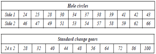
6.5.1 Indexing required
- Indexing = 40
?
= 40/120
= 1 x 22
3 22
= 22/66
Indexing is 22 holes in a 66-hole circle. (3)
6.5.2 Change of gears
- Gear ratio : ?????? = ?−? x 40
?????? ? 1
= 120 −113 x 40
120
= + 7 x 8
3 8
= 56/24 - The driver gear has 56 teeth.
- The driven gear has 24 teeth. (5)
6.5.3
- The direction of motion is clockwise.
- The crank handle will turn the same direction as the index plate (1)
6.6 Dove tail calculations:
- Find the difference of distance over the rollers (L):
L = (M ‒ R) – (m ‒ r)
= (127,64 ‒ 25) – (100,32 ‒ 15)
= 102,64 – 85,32
L = 17,32 mm
For the angle θ
Tan θ/2 = (R ‒ r) / L
= 10/17,32
Θ = 30 x 2
Θ = 60° (6)
6.7 Constraints to balancing
- Requires specialised machinery
- Difficult to ascertain the exact point of unbalance
- Requires accurate removal or addition of material’s weight to the object.
- Can lead to interference with parts of the machine when weights are added to parts (Any 2 x 1) (2)
[28]
QUESTION 7: TOOLS AND EQUIPMENT (SPECIFIC)
7.1 Hardness testers:
7.1.1 Brinell hardness tester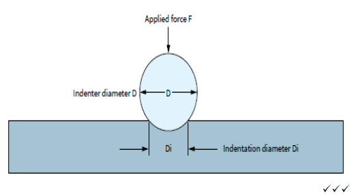 (3)
(3)
7.1.2 Rockwell hardness tester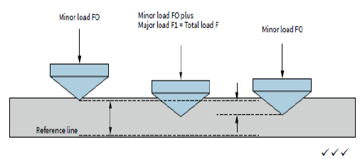 (3)
(3)
7.2 Hardness measure of a metal
- Resistance to penetration
- Elastic hardness
- Resistance to abrasion (3)
7.3 Screw-thread micrometres
- 6 + 0,5 + 0,3 = 6,80 mm (2)
7.4 Micrometre reading
- 41,25 mm
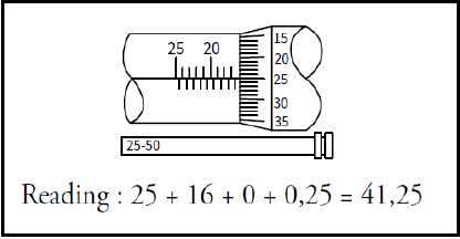 (2)
(2)
[13]
QUESTION 8: FORCES (SPECIFIC)
8.1 Resultant force calculations: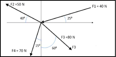
- Xcom = 80 cos 30 – 40 cos 75 – 70 cos 25 – 50 cos 40
= 80,0686 N - Ycom = 50 sin 40 – 80 sin 30 – 70sin 25 – 40 sin 75
= ‒16,91 N - R = √(?2 + ?²)
R = 81,836 N
Tan θ = y/x
Tan Θ = 16,91/80,0
Θ = 360 ‒ 11,925°
= 348,075°
Equilibrant = Resultant BUT IN THE OPPOSITE DIRECTION
Equilibrant = 81,836 N at 168,075° (12)
8.2 Moments
- Converting the UDL to point lolad
1 x 10 = 10 kN @ 5 mm from eft hand end
Calculation of the reactions.Taking moments:
- RD x 20 = (5 x 5) + (10 x 30) + (20 x 15)
= 31,25 kN
(Ra x 20) + (10 x 10) = (20 x 5) + (5 x15)
= 3,75 kN (5)
8.3 Stress calculations:
8.3.1 Tensile Stress Calculations
- F = 10 kN; d = 20 mm: L = 2 m : E = 200 PGa
? = ?
?
? = ??2
A = π x 0,01²
A = 3,141 x 10^-4 m² - δ = ?
?
= 10 000/3.141 x 10 ^-4
= 318,31 x 10⁶ Pa
= 318,31 MPa (4)
8.3.2 The change in length calculations.
- ?? = ?; E = 200 GPa; F = 10 kN; L = 2 m; Ϭ = 318,31 MPa
?? = s × L
?
= 318,31 x 10⁶ x 2) / 200 x 10⁹
= 0,318 mm (4)
8.4 Stress/Strain diagram: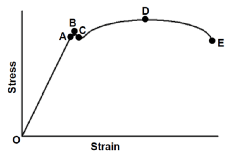
- A – Limit of proportionality
- B – Elastic limit
- C – Yield point
- D – Maximum force / point
- E – Point of fracture (6)
8.5 FOS stands for Factor OR Safety or Safety Factor. (1)
8.6 Young’s modulus states that stress in metal is directly proportional to the strain it causes, provided the limit of proportionality is not exceeded. (1)
[33]
QUESTION 9: MAINTENANCE (SPECIFIC)
9.1 Purpose of composites:
9.1.1 Bakelite can be used in disc brake cylinders, saucepan handles, distributor rotors, electrical plugs and switches, and parts for electrical irons. (2)
9.1.2 Fibre glass is used as a surface covering, woven cloth, wearing fibres, plastic covers and stuffing for pillow. (2)
9.1.3 Carbon fibre is used for sport equipment like tennis, squash and badminton racquets, racing bicycle frames, construction skis, surfboards and boat masts, compressor blades for jet engines. (2)
9.2 Reasons for using cutting fluid when working on the centre lathe:
- It prolongs the life of a cutting tool.
- It prevents the shavings or metal chips from sticking and fusing to the cutting tool.
- It will carry away the heat generated by the turning process.
- It flushes away shavings/metal chips.
- It improves the quality of the finish of the turned surface.
(Any 1 x 1) (1)
9.3 Mechanical drives:
- Gear drives
- Chain drives
- Belt drives (3)
9.4 Reasons for the use of carbon fibre:
- It is light in weight
- It is tougher and stronger
- It can be bent to any shape when heated above 150 ºC (Any 2 x 1) (2)
9.5 ONE property and ONE use of each composite
COMPOSITE | PROPERTY | USES |
9.5.1 PVC |
(Any 1 x 1) |
(Any 1 x 1) |
9.5.2 Vesconite |
(Any 1 x 1) |
(Any 1 x 1) |
9.5.3 Nylon |
(Any 1 x 1) |
(Any 1 x 1) |
(6) [18]
QUESTION 10:
JOINING METHODS (SPECIFIC)
10.1 Square thread calculations:
10.1.1
- PCD = T x m
= 60 x 4 = 240 mm
10.1.2 Add = Module = 4
10.1.3
- Clearance = 0,157 x m
= 0,628 mm
10.1.4
- Ded = 1,157 x m
= 4,628 mm
10.1.5
- OD = PCD + 2 x m
= 248 mm
10.2 Left-hand square screw-thread:
- A – Leading angle
- B – Following or Trailing Angle
- C – Clearance
- D – Helix angle (4)
10.3 A multi-start thread allows for faster travel or movement and is more efficient as it loses less power to friction compared to single-start thread. (2 )
10.4 Screw-thread fit is a combination of allowances and tolerances and a measure of tightness or looseness between the bolt and nut. (2)
[18]
QUESTION 11: SYSTEMS AND CONTROL (SPECIFIC)
11.1 Gear drives work on the principle that the turning motion of one gear be transferred to another gear if the gears are mounted close so that they mesh or
engage. (2)
11.2 Hydraulic system calculations:
11.2.1 Calculate the force applied on Piston A.
- da = 30 mm; Db = 130 mm; M = 2 000 kg
Weight Calculation (W)
W = m x g
= 2 000 x 10
= 20 Kn (2)
11.2.2
- A = π (r)²
= π x 0,065²
= 0,0133 m ²
? = ?
?
= 20 000/0,0133
= 1,507 MPa
11.2.3
- A = ?Da²/4
= ? (0,03)²/4
= 7,0686 x10⁻⁴ m²
F = P x A
= 1,507 x 10 ⁶ x 7,068 x 10−4
Force = 1065,235 N (4)
11.2.4 Hydraulic system applications:
- Machine tools, motor vehicle, hydraulic jacks (Any 1 x 1) (1)
11.3 Velocity ratio is defined as the ratio of a distance through which any part of a machine moves, to that which the driving part moves during the same time.(2)
11.4 Belt drive calculations:
- Nmotor x Dmotor = Nblade x Dblade
135 x 1 200 = 395 x Dblade
Dblade = 410,127 rpm (3)
11.5 Pneumatic drives:
- Vehicle painting
- Air brakes
- Opening and closing doors
- Dismantling vehicle tire (Any 3 x 1) (3)
11.6 Simple gear calculations:
- TA = 56 teeth; NA = 700 rpm
11.6.1 TB = ?? X ??
??
= (56 x 700)/ 980
= 40 teeth (3)
11.6.2
- Nc = ?? X ??
??
= (40 x 980)/ 64
= 612,5 rpm (3)
11.6.3 Driven gear will rotate anti-clockwise (1)
[28]
TOTAL: 200