Electrical Technology: Power Systems Grade 12 Questions - NSC Past Papers And Memos September 2020 Preparatory Examinations
Share via Whatsapp Join our WhatsApp Group Join our Telegram GroupINSTRUCTIONS AND INFORMATION
- This question paper consists of SIX questions.
- Answer ALL the questions.
- Show ALL calculations and round off answers correctly to TWO decimal places.
- Number the answers correctly according to the numbering system used in this question paper.
- Sketches and diagrams must be large, neat and FULLY LABELLED.
- You may use a non-programmable calculator.
- Calculations must include:
7.1 Formulae and manipulations where needed
7.2 Correct replacement of values
7.3 Correct answers and relevant units where applicable - A formula sheet is provided at the end of this question paper.
- Write neatly and legibly.
QUESTIONS
QUESTION 1: OCCUPATIONAL HEALTH AND SAFETY
1.1 Define the term accident with reference to the Occupational Health and Safety Act, 1993 (Act 85 of 1993). (2)
1.2 Explain TWO general duties of employees in the workplace. (2)
1.3 State TWO unsafe conditions in a school workshop that can cause an accident. (2)
1.4 Briefly explain a third-degree burn. (2)
1.5 State TWO functions of a health and safety representative. (2)
[10]
QUESTION 2: RLC
2.1 Explain the phase relationship between current and voltage in the following AC circuit:
2.1.1 A pure capacitive circuit (2)
2.1.2 A pure inductive circuit (2)
2.1.3 A resistive circuit (2)
2.2 Refer to the circuit diagram FIGURE 2.2 below and answer the questions that follow.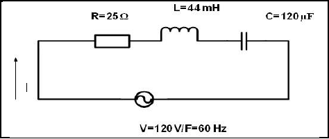
FIGURE 2.2: RLC CIRCUIT
Calculate the:
2.2.1 Inductive reactance (3)
2.2.2 Capacitive reactance (3)
2.2.3 Impedance of the circuit (3)
2.2.4 Total current flow through the circuit (3)
2.3 Explain how the value of the capacitive reactance will be affected if the supply frequency is increased. (3)
2.4 A parallel circuit in FIGURE 2.5 consists of a capacitor that draws a current of 4 A, an inductor that draws a current of 6 A and a resistor that draws a current of 5 A. All the components are connected to 240 V / 50 Hz supply.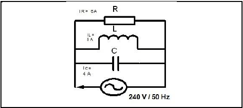
FIGURE 2.5: RLC PARALLEL CIRCUIT
Calculate:
2.4.1 The total current through the circuit (3)
2.4.2 The phase angle (3)
2.4.3 The inductive reactance (3)
2.4.4 The capacitive reactance (3)
2.5 A parallel RLC circuit consists of a 10 Ω resistor and a 0,05 µF and a 0,2 H inductor connected across a 120 V supply. Calculate the:
2.5.1 Resonant frequency (3)
2.5.2 Q-factor (4)
2.5.3 Bandwidth (3)
2.6 A series RLC tuned circuit has a resonant frequency of 95 MHz and a bandwidth of 200 kHz. The capacitor is 2,5 pF and the wire used to wind the coil has zero resistance. Calculate:
2.6.1 The Q factor of the circuit (3)
2.6.2 The size of the inductor (2)
2.6.3 The circuit resistance (2)
[50]
QUESTION 3: THREE-PHASE AC GENERATION
3.1 Draw a neat, labelled schematic representation of a star connected power system. Show all voltages and phasors. (4)
3.2 State the functions of the following meters:
3.2.1 Kilowatt-hour meter (2)
3.2.2 Wattmeter (1)
3.3 Name TWO disadvantages of a single-phase system when compared to a three-phase system. (2)
3.4 Refer to FIGURE 3.4 below and answer the questions that follow.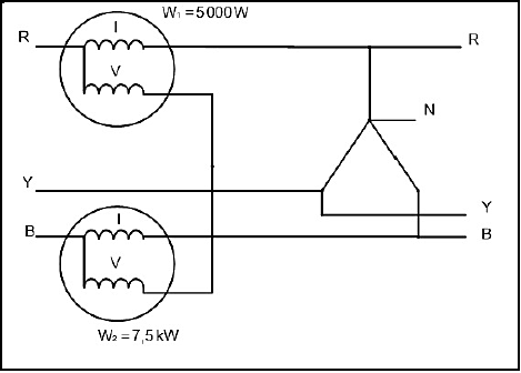
FIGURE 3.4
3.4.1 Describe how the two watt meters are connected to the star system. (3)
3.4.2 Calculate the total power of the three-phase system. (3)
3.4.3 Calculate the power factor of the system. (5)
3.5 A 380 V three-phase system is star connected to a lagging load. The input power is 25 kW and the load causes a lagging power factor of 0,8.
Given :
- VL = 380 V
- PIN = 25 kW
- cos θ = 0,8
Calculate:
3.5.1 The phase voltage (3)
3.5.2 The line current to the load (3)
3.5.3 The reactive power (3)
3.6 Explain why the power supply to dwellings cannot be connected in delta. (2)
3.7 Describe how a low power factor affects an AC electrical power system. (4)
3.8 Discuss the following stages of three-phase AC generation from the supplier to the consumer.
3.8.1 Generation (2)
3.8.2 Transmission (2)
3.8.3 Mention ONE type of consumer that receives electricity from intermediate substations. (1)
[40]
QUESTION 4: THREE-PHASE TRANSFORMERS
4.1 Name TWO types of transformer configurations available when manufacturing three-phase transformers. (2)
4.2 Mention the reasons for mounting the magnetic circuit and windings of power transformers in mineral oil. (2)
4.3 Mention TWO types of protection devices used for the protection of transformers. (2)
4.4 State TWO cooling methods used for oil-immersed transformers. (2)
4.5 Name the type of induction that takes place between the primary and secondary coils of a transformer. (1)
4.6 A 20 kVA delta-star transformer has a primary voltage of 6 kV and a secondary voltage of 1 000 V. The losses amount to 160 W and the power factor is 0,88.
Given:
- S = 20 kVA
- VLP = 6 kV
- VLS = 500 V
- PLOSSES = 160 W
- cos θ = 0,88
Calculate:
4.6.1 The secondary line current (3)
4.6.2 The transformation ratio (6)
4.6.3 The input power (3)
4.6.4 The efficiency of the transformer (3)
4.7 Explain why transformers have a better efficiency than motors. (3)
4.8 Explain why a transformer only operates with an AC supply. (3)
[30]
QUESTION 5: THREE-PHASE MOTORS AND STARTERS
5.1 Define the term slip with reference to a three-phase AC induction motor. (2)
5.2 Give TWO reasons why the rotor of an induction motor is skewed. (2)
5.3 One of the electrical tests performed on the stator of a three-phase motor is the insulation resistance test between windings and earth.
5.3.1 State the reasons for performing this test. (2)
5.3.2 Write down the accepted value for a motor to pass this test. (1)
5.4 State the main function of a three-phase motor starter. (1)
5.5 Refer to the control circuit in FIGURE 5.5 and answer the questions that follow.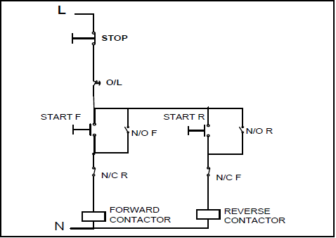
FIGURE 5.5: CONTROL CIRCUIT
5.5.1 Identify the starter shown in FIGURE 5.5. (1)
5.5.2 Describe the function of the two normally closed contacts in the circuit. (2)
5.5.3 Explain what happens if the circuit is energised and the start forward button is pressed. (4)
5.5.4 Describe the function of the overload contact in the circuit. (2)
5.5.5 Explain how a faulty N/O R that remains stuck in the closed position, would affect the operation of the starter. (4)
5.6 A manual sequence starter has the following sequence:
- Motor 1 must start before Motor 2
- Each motor must have independent overload protection
- A stop button controls both motors
Draw the control circuit of the sequence starter. (6)
5.7 A delta connected three-phase motor has a phase voltage of 380 V with a power factor of 0,866. The line current is 25 A when the motor is connected to the supply. Calculate the input power to the motor.
Given:
- VPH = 380 V
- cos θ = 0,866
- IL = 25 A (3)
5.8 Define the term synchronous speed of a motor. (2)
5.9 A three-phase motor with 24 poles has a synchronous speed of 1 200 rpm. Determine the percentage slip if the rotor speed is 1 140 rpm.
Given:
- Poles = 24
- NS = 1 200 rpm
- NP = 1 140 rpm (3)
5.10 Mention THREE types of information that can be found on the nameplate of a motor. (3)
5.11 A 110 V / 60 Hz three-phase motor is connected to a supply in a factory in South Africa. State with a reason if the motor will operate. (2)
[40]
QUESTION 6: PROGRAMMABLE LOGIC CONTROLLERS (PLC’s)
6.1 Choose a description from COLUMN B that matches with the term in COLUMN A. Write only the letter (A–E) in COLUMN B next to the question number (6.1.1–6.1.5) in COLUMN A, for example 6.1.6 G.
COLUMN A | COLUMN B | ||
6.1.1 | Input device | A | Brain of the PLC |
6.1.2 | Hardware | B | Disadvantage of hardwiring |
6.1.3 | Processor | C | Physical parts and components |
6.1.4 | Output | D | Sensor |
6.1.5 | Bulky | E | Motor |
(5 x 1) (5)
6.2 Explain why software is installed. (3)
6.3 Refer to FIGURE 6.3 below and answer the questions that follow.
INPUT A | INPUT B | OUTPUT (F) |
0 | 0 | 1 |
0 | 1 | 0 |
1 | 0 | 0 |
1 | 1 | 0 |
FIGURE 6.3: TRUTH TABLE
6.3.1 Draw the ladder diagram that this truth table represents. (3)
6.3.2 Draw the logic gate symbol that this truth table represents. (3)
6.4 Define an opto-isolator. (3)
6.5 State TWO applications of light sensors. (2)
6.6 Describe the function of the timer used in PLC programs. (2)
6.7 Refer to FIGURE 6.7 and draw a logic ladder diagram that executes the same function as the one in FIGURE 6.7.
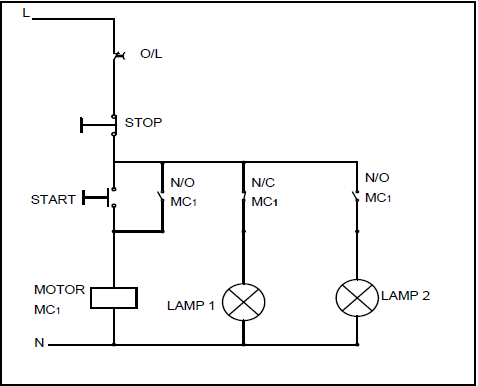
FIGURE 6.7
NOTE: The circuit is energised. (9)
[30]
TOTAL: 200
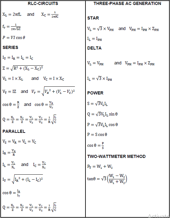
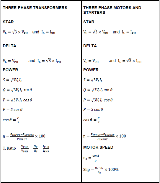
FORMULA SHEET