Mechanical Technology: Fitting and Machining Grade 12 Questions - NSC Exams Past Papers and Memos September 2019 Preparatory Examinations
Share via Whatsapp Join our WhatsApp Group Join our Telegram GroupINSTRUCTIONS AND INFORMATION
- Write your name on the ANSWER BOOK.
- Read ALL the questions carefully.
- Answer ALL the questions.
- Number the answers correctly according to the numbering system used in this question paper.
- Start EACH question on a NEW page.
- Show ALL calculations and units. Round off final answers to TWO decimal places.
- You may use a non-programmable scientific calculator and drawing instruments.
- The value of gravitational force should be taken as 10 m/s2.
- All dimensions are in millimetres, unless stated otherwise in the question.
- A formula sheet is attached to the question paper.
- Write neatly and legibly.
- Use the criteria below to assist you with your time management.
QUESTION | CONTENT COVERED | MARKS | TIME |
Generic | |||
1 | Multiple-choice questions | 6 | 6 minutes |
2 | Safety | 10 | 10 minutes |
3 | Materials | 14 | 14 minutes |
Specific | |||
4 | Multiple-choice questions | 14 | 10 minutes |
5 | Terminology (Lathe and Milling Machine) | 18 | 20 minutes |
6 | Terminology | 28 | 10 minutes |
7 | Tools and Equipment | 13 | 40 minutes |
8 | Forces | 33 | 20 minutes |
9 | Maintenance | 18 | 20 minutes |
10 | Joining Methods (Stresses and Distortion) | 18 | 10 minutes |
11 | Systems and Control (Drive Systems) | 28 | 20 minutes |
TOTAL | 200 | 180 minutes |
QUESTIONS
QUESTION 1: MULTIPLE-CHOICE QUESTIONS (GENERIC)
Various options are provided as possible answers to the following questions. Choose the correct answer and write only the letter (A–D) next to the question numbers (1.1–1.6) in the ANSWER BOOK, for example 1.7 A.
1.1 Which of the following is NOT a basic first aid treatment?
- Examination
- Diagnosis
- Operate
- Basic comfort and safety (1)
1.2 Which ONE of the following items of personal protective equipment (PPE) is applicable when performing arc welding?
- Welding helmet
- Welding goggles
- Hard hat
- Dust mask (1)
1.3 Which of the following is a safety precaution in relation to the use of a bench grinder?
- The tool rest must be not more than 3 mm from the grinding wheel.
- Make sure the chuck is correctly tightened.
- Stand to the side when switching on the machine.
- Do not wear safety goggles. (1)
1.4 What is the colour of an oxygen gas cylinder?
- Maroon
- Grey
- Green
- Black (1)
1.5 Stopping devices on machinery are normally … in colour.
- red
- green
- black
- orange (1)
1.6 What is the maximum thickness of sheet metal that can be cut using a hand guillotine?
- 3,2 mm
- 1,6 mm
- 1,2 mm
- 2,1 mm (1) [6]
QUESTION 2: SAFETY (GENERIC)
2.1 Give TWO reasons why it is important to wear a helmet during arc welding.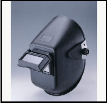 (2)
(2)
2.2 State TWO safety measures to be used when using an angle grinder. (2)
2.3 What is the maximum gap that the tool rest should be set from the grinding wheel of a bench grinder?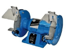 (1)
(1)
2.4 Give THREE safety rules to be applied when using a band saw. (3)
2.5 State TWO safety precautions that must be observed when handling gas cylinders.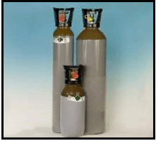 (2)
(2)
[10]
QUESTION 3: MATERIALS (GENERIC)
3.1 Explain what you understand about quenching during the heat treatment process.(3)
3.2 Why is brine better than fresh water in quenching heat-treated materials? (2)
3.3 State the purpose for case-hardening mild steel. (3)
3.4 Name TWO methods by which case-hardening can be done. (2)
3.5 Explain the difference between annealing and normalising. (4) [14]
QUESTION 4: MULTIPLE CHOICE (SPECIFIC)
Various options are provided as possible answers to the following questions. Choose the correct answer and write only the letter (A–D) next to the question number (4.1–4.14) in the ANSWER BOOK, for example 4.15 A.
4.1 Which lathe operation is shown in FIGURE 4.1?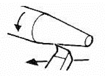
FIGURE 4.1
- Straight turning
- Taper turning
- Thread cutting
- Reaming (1)
4.2 Identify the type of milling cutter shown in FIGURE 4.2.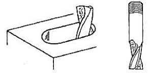
FIGURE 4.2
- Plain straight-tooth cutter
- Straight-tooth side-milling cutter
- Slitting saw
- Shell end/flute mill (1)
4.3 Which ONE of the following indexing methods can be used to machine a spur gear with 119 teeth on a milling machine?
- Simple indexing
- Angular indexing
- Differential indexing
- All the above-mentioned (1)
4.4Compressive stress is stress that acts …
- against the lengthening of an object
- perpendicular to the surface
- parallel to a surface
- against the shortening of an object (1)
4.5 What will be the deformation of a bar that is 0,73 m long, when the strain is 0,5 x 10⁻³ ?
- 0,653 mm
- 0,036 mm
- 0,498 mm
- 0,365 mm (1)
4.6 The main reason for performing a hardness test on engineering materials is to determine the …
- elasticity of the material.
- resistance of the material against denting.
- corrosion of the material.
- fluidity of the metal. (1)
4.7 What does the symbol ‘F’ denote in the Brinell hardness test shown in FIGURE 4.7 below?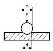
FIGURE 4.7
- Ball diameter
- Hardness number
- Focus point
- Force applied (1)
4.8 Which ONE of the following engineering materials is a thermo-hardened composite?
- Teflon
- Bakelite
- Bronze
- White metal (1)
4.9 What will the spindle speed be if you were milling a material having a cutting speed of 35 m/min with a cutter of 50 mm in diameter?
- 233 r/min
- 223 r/min
- 322 r/s
- 232 r/min (1)
4.10 Which ONE of the following indexing methods can be used to mill an angle of 61º:20?
- Angular indexing
- Simple indexing
- Rapid indexing
- None of the above-mentioned (1)
4.11 Shearing stress is stress that …
- twist and turns until fracture occurs.
- acts perpendicular to the surface.
- acts against the lengthening of an object.
- acts on opposite faces of the section/opposite parallel forces. (1)
4.12 The pulley system shown in FIGURE 4.12 below is a …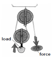
FIGURE 4.12
- nylon pulley.
- block and tackle system.
- control system.
- timing pulley. (1)
4.13 The unit for power is …
- newtons.
- metre.
- pascal.
- watt. (1)
4.14 Identify the symbol, shown in FIGURE 4.14 below, which relates to a pneumatic system.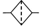
FIGURE 4.14
- Valve
- Fitter
- Compressor
- Motor (1) [14]
QUESTION 5: TERMINOLOGY (LATHE AND MILLING MACHINE) (SPECIFIC)
5.1 Describe the function of the following centre lathe components:
5.1.1 Lead screw (2)
5.1.2 Tailstock (2)
5.1.3 Lathe steadies (2)
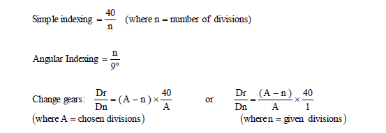
5.2 Give the reason for using the dividing head on a milling machine. (1)
5.3 A 55 mm diameter shaft, 450 mm long, must be taper-turned with an included angle of 8,5º for a length of 250 mm. Calculate the small diameter of the taper.
(5)
5.4 FIGURE 5.4 shows a drawing of a keyway being cut on a shaft.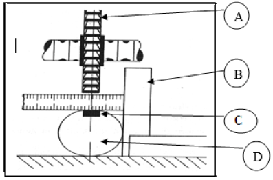
FIGURE 5.4
Label parts A–D. (4)
5.5 Calculate the lead of a triple start thread with a 2,5 mm pitch. (2) [18]
QUESTION 6: TERMINOLOGY (SPECIFIC)
6.1 Explain with the aid of sketches (diagrams) what is meant by:
6.1.1 Down cut milling (2)
6.1.2 Up cut milling (2)
6.1.3 Straddle milling (2)
6.2 State ONE advantage of using the tailstock set-over method to cut an external taper on a centre lathe.(1)
6.3 Define the term ‘module’ as applied to gears. (1)
6.4 Explain what you understand by the gear ratio of a dividing head being 40 : 1. (2)
6.5 Calculate the differential indexing for 119 divisions determining:
6.5.1 The indexing required (Hint: Choose 120 divisions) (3)
6.5.2 The change gears required (5)
6.5.3 The direction of rotation of the index plate in relation to crank handle (1)
6.6 The drawing in FIGURE 6.7 shows two precision rollers placed in an external dovetail.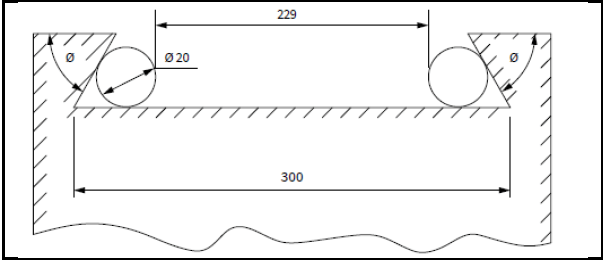
Calculate the angle θ using the given values in the drawing. (7)
6.7 Name TWO types of dimension positioning applicable to a CNC centre lathe. (2) [28]
QUESTION 7: TOOLS AND EQUIPMENT (SPECIFIC)
7.1 Describe the purpose and operation of the following testers:
7.1.1 Tensile tester (2)
7.1.2 Moment tester (2)
7.2 Give TWO instances where you can use a depth gauge. (2)
7.3 Determine the readings of the screw thread micrometres shown in FIGURE 7.3. (2)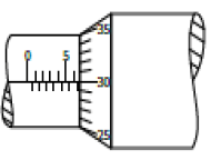
FIGURE 7.3
7.4 State the steps to be followed when setting up the Brinell Hardness tester and making the test. (5) [13]
QUESTION 8: FORCES (SPECIFIC)
8.1 FIGURE 8.1 below shows a system of forces with four concurrent applied forces. Calculate the magnitude and direction of the equilibrant of this system of forces.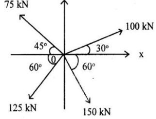 (13)
(13)
FIGURE 8.1
8.2 The diagram in FIGURE 8.2 below shows a beam with two vertically applied point loads of 20 kN and 30 kN and also a 5 kN/m uniformly distributed load on it.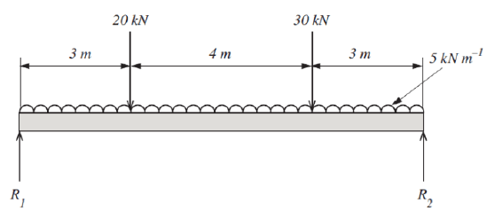
FIGURE 8.2
Calculate the magnitude of reactions R1 and R2. (5)
8.3 A load of 12 Kn causes a tensile stress of 24,5 MPa in a brass round bar. The original length of the bar is 250 mm and Young’s modulus for brass is 90 GPa.
8.3.1 Calculate the diameter, in millimetres, of the brass bar. (5)
8.3.2 Calculate the change in length, in millimetres, caused by the load. (5)
8.4 FIGURE 8.4 below is the stress/strain diagram.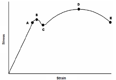
FIGURE 8.4
Indicate what points A–E represent. (5) [33]
QUESTION 9: MAINTENANCE (SPECIFIC)
9.1 Write down the following abbreviations in full:
9.1.1 PVC (1)
9.1.2 GRP (1)
9.1.3 LDPE (1)
9.2 Why is it essential to use a cutting fluid on a milling or centre lathe? (1)
9.3 Name the THREE factors that influence the coefficient of friction. (3)
9.4 Give TWO reasons for using carbon fibre in the manufacture of bicycle frames. (2)
9.5 In tabulated form compare ONE property and ONE use of the following thermoplastic materials:
9.5.1 Vesconite (2)
9.5.2 Teflon (2)
9.5.3 Nylon (2)
9.6 State the THREE possible consequences for failure to do maintenance. (3) [18]
QUESTION 10: JOINING METHODS (SPECIFIC)
10.1 A two-start square thread with a lead of 45 mm has an outside diameter of 84 mm and a clearance of 3º. Calculate the:
10.1.1 Helix angle of the thread (4)
10.1.2 Leading angle of the thread (3)
10.1.3 Trailing tool angle (3)
10.2 With the aid of a sketch, show the screw profile, the included thread angle, the root diameter, the major diameter, tooth thickness and the pitch (mean) diameter of an ISO metric screw thread.(6)
10.3 Convert 40,125º decimal into dms (degrees, minutes and seconds) (2) [18]
QUESTION 11: SYSTEMS AND CONTROL (SPECIFIC)
11.1 Describe the principle of operation of a gear drive. (2)
11.2 A hydraulic system is being used to move machine parts during the assembling process. The specifications of the system are diagrammatically presented in FIGURE 11.2.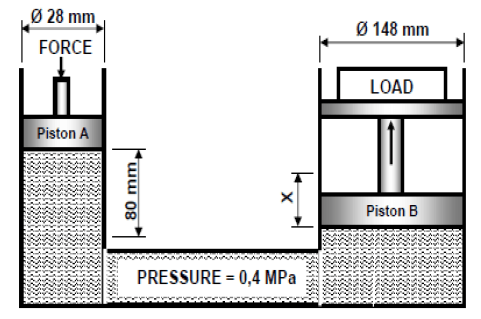
FIGURE 11.2
Calculate the following:
11.2.1 The force applied to piston A (5)
11.2.2 The distance X, in millimetres, that piston B will move with 10 strokes of piston A (6)
11.3 State TWO functions of the reservoir in a hydraulic system. (2)
11.4 A power saw’s motor has a pulley, 125 mm in diameter, that turns at 1100 rpm. The speed at which the driven pulley drives the saw blades is 375 rpm.
Calculate the diameter of the driven pulley. (3)
11.5 Give TWO advantages of belt drives. (2)
11.6 FIGURE 11.6 shows a gear drive system. A driver gear on the shaft of an electric motor has 24 teeth and meshes with a gear on a counter shaft with 40 teeth. On this counter shaft is another driver gear with 20 teeth that meshes with a gear with 48 teeth on a second counter shaft. The second counter shaft has a driver gear with 42 teeth which drives a gear with 90 teeth on the output shaft.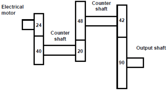
FIGURE 11.6
Calculate the following:
11.6.1 The rotational frequency of the output shaft if the electric motor rotates at 1440 r/min. (4)
11.6.2 The velocity ratio between the input and output shaft. (3)
11.7 Derive the units for Torque. (1) [28]
TOTAL: 200
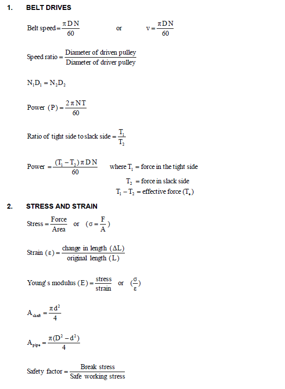
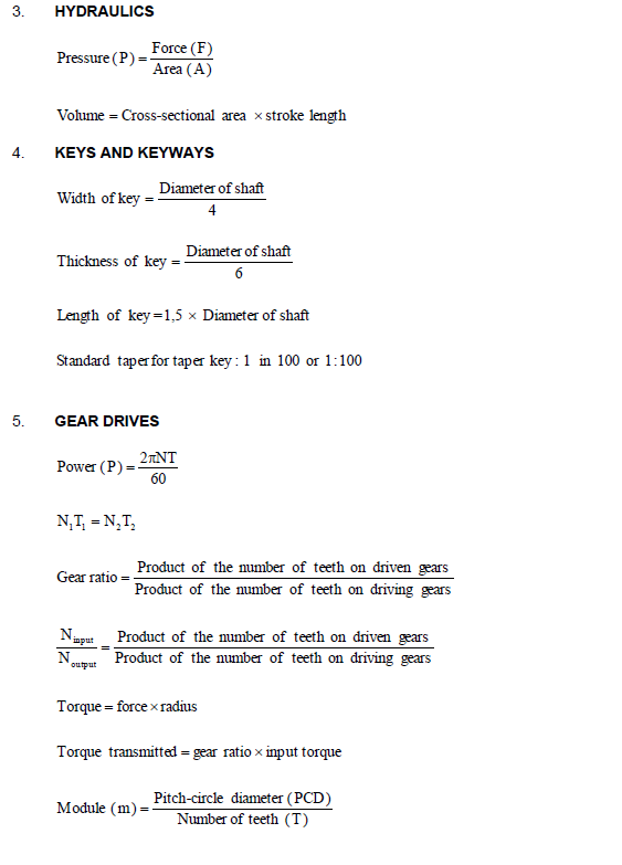
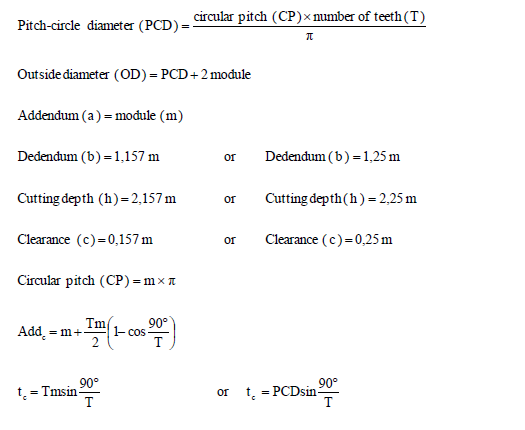
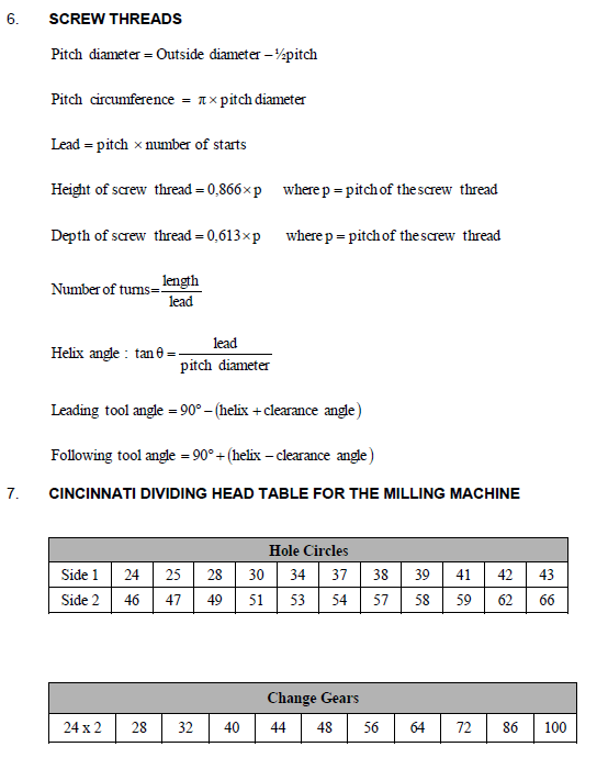
FORMULA SHEET FOR MECHANICAL TECHNOLOGY
(FITTING AND MACHINING)