Mechanical Technology: Fitting and Machining Grade 12 Memorandum - NSC Exams Past Papers and Memos September 2019 Preparatory Examinations
Share via Whatsapp Join our WhatsApp Group Join our Telegram GroupMARKING GUIDELINE
QUESTION 1: MULTIPLE-CHOICE QUESTIONS (GENERIC)
1.1 C (1)
1.2 A (1)
1.3 B (1)
1.4 D (1)
1.5 A (1)
1.6 C (1) [6]
QUESTION 2: SAFETY (GENERIC)
2.1 Reason for wearing a helmet:
- Protects your eyes from ultra violet rays and infra-red rays. (2)
2.2 Angle grinder safety:
- Safety guard must be in place before grinding.
- Protective shields must be placed around the object being ground to protect passers-by.
- Use the correct grinding disc for the job.
- Do not use excessive force while grinding and cutting.
- Make sure there are no excessive force while grinding and cutting.
- Make sure there are no cracks on the disc before you start a job.
- Protective clothing and eye protection are essential. (Any 2) (2)
2.3 Maximum gap – bench grinder:
- 3 mm (1)
2.4 Band saw safety:
- Wear safety glasses or a face shield.
- wear protective footwear when required.
- Make sure all guards are in place.
- Check for correct tension on the blade.
- Use blades that are sharp, properly set and suitable for the job.
- Keep the floor clean and free of obstructions or clutter. (Any 3) (3)
2.5 Gas cylinder safety precautions:
- Always store and use gas cylinders in an upright position.
- Never stack cylinders on top of one another.
- Do not bang or work on the cylinders.
- Never allow cylinders to fall.
- No oil and grease should come into contact with gas cylinders or fittings.
- Keep the caps on the cylinders for protection. (Any 2) (2) [10]
QUESTION 3: MATERIALS (GENERIC)
3.1 Quenching:
- Quenching means to cool the heated material rapidly.
- Cooling the material to room temperature.
- Water is normally used for low and medium carbon steels.
- Oil is used on high carbon and alloy steel.
- Extreme cooling brine is used. (Any 3) (3)
3.2 Difference between brine and salt water:
- Brine hardens steels better than fresh water, salt inhibits the water from dissolving into atmospheric gas.
- Salt water does not vaporise as quickly as fresh water. (2)
3.3 Purpose for case-hardening:
- It hardens the surface.
- It provides a wear resistant surface.
- Strengthens core to withstand applied loads. (3)
3.4 Methods of case-hardening:
- Mild steel can be surface hardened by heating to its critical range and immersing in case hardening compound. Carbon is absorbed into surface layer of steel.
- Mild steel can be heated in an atmosphere of nitrogen called Nitriding. (Any 1 x 2) (2)
3.5 Difference between annealing and normalising:
- Annealing requires steel to cool down over an extended period thus resulting in an internal structural change in the steel, making it softer.
- Normalising merely removes work-related stresses. (4) [14]
QUESTION 4: MULTIPLE-CHOICE QUESTIONS (SPECIFIC)
4.1 B (1)
4.2 D (1)
4.3 C (1)
4.4 A (1)
4.5 D (1)
4.6 B (1)
4.7 D (1)
4.8 B (1)
4.9 B (1)
4.10 A (1)
4.11 D (1)
4.12 B (1)
4.13 D (1)
4.14 B (1) [14]
QUESTION 5: TERMINOLOGY (LATHE AND MILLING MACHINE) (SPECIFIC)
5.1 Lathe components:
5.1.1 Lead screw transmits feed motion for screw-cutting and extends the length of the bed, passing behind the apron. (2)
5.1.2 Tailstock stocks supports the free end of work and is also in drilling, reaming and taper turning operations of work held in the chuck or on the faceplate. (2)
5.1.3 Lathe steadies is used to support long pieces of small-diameter must be machined in a centre lathe. To prevent them from bending additional support on the free end. (2)
5.2 Diving head: Is a supplementary component used to break up the circumference of a circular workpiece into a number of equal parts. (1)
5.3 Taper-turning calculations:
- Θ = 8,5 º
θ/2 = 4,25º
Tan θ/2 = (D – d )/ 2L
Tan 4,25 x 2 x 250 = (55-d)
d = 17,84 mm
d = 18 mm (5)
5.4 Keyway cut:
- A – Side and face cutter
- B – Engineers Square
- C – Key way
- D – Work piece (4)
5.5 Lead Calculations:
- Lead = No. of starts x pitch
= 3 x 2,5 mm
= 7,5 mm (2) [18]
QUESTION 6: TERMINOLOGY (INDEXING) (SPECIFIC)
6.1 GEAR CALCULATIONS:
6.1.1 Down Cutting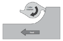 (2)
(2)
6.1.2 Up-cutting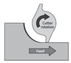 (2)
(2)
6.1.3 Straddle milling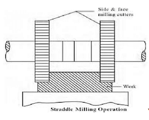 (2)
(2)
6.2 Advantages of tailstock set-over method:
- Long and accurate tapers can be cut. (1)
6.3 Module is the ratio of pitch diameter to the number of the teeth, generally regarded as tooth size. (1)
6.4 Gear ration of dividing is 40 : 1 meaning 40 revolutions of the worm shaft to one turn of the worm gear. (2)
6.5 Differential indexing
| Hole circles | |||||||||||
| Side 1 | 24 | 25 | 28 | 30 | 34 | 37 | 38 | 39 | 41 | 42 | 43 |
| Side 2 | 46 | 47 | 49 | 51 | 53 | 54 | 57 | 58 | 59 | 62 | 66 |
| Standard change gears | |||||||||||
| 24 × 2 | 28 | 32 | 40 | 44 | 48 | 56 | 64 | 72 | 86 | 100 | |
6.5.1 Simple indexing
- Indexing = 40 = 40
N 119
Actual indexing = 40
A
= 40 = 4 × 2
120 12 × 2
= 8 (3)
24
Zero full turns and 8 holes on the 24-hole circle
6.5.2 Change of gears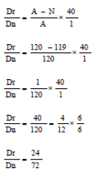 (5)
(5)
6.5.3 The direction of motion is clockwise.
- The crank handle will turn the same direction as index plate.(1)
6.6 Dove tail calculations:
- Dovetail calculations
? = ? = 10 ??
2
? = ?
2
tan ? = ?
?
W = 229 mm
X = 300 mm
300 = 2a + 2R + 229
300 = (2 x a) + (2 x 10) + 229
a = 25,5 mm
α = 21,41º
θ = 2 x a
θ = 42,825º (7)
6.7 Reference Systems:
- Absolute Measurements
- Incremental measurements (2) [28]
QUESTION 7: TOOLS AND EQUIPMENT (SPECIFIC)
7.1 Testers:
7.1.1 Tensile tester is a destructive tester that subjects a piece of material to an increasing axial load while measuring the corresponding elongation of the material. (2)
7.1.2 Moments testers is used to determine the reactions on either side of a simply loaded beam and illustrate the concept of the triangle of forces. (2)
7.2 Depth gauge:
- open container
- pipe or cylinders (2)
7.3 Screw thread micrometres
- 6 + 0,5 + 0,3 = 6,80 mm (2)
7.4 Setting up the Brinell Hardness tester:
- The desired load in kilograms is selected on the dial by adjusting the air regulator.
- The specimen is placed on the anvil.
- The specimen is raised to be in contact with the Brinell ball by turning the hand wheel.
- The load is then applied by pulling out the plunger control.
- Remove the specimen from the tester and measure the diameter of the impression.
- Determine the Brinell hardness number by calculation or by using the table. (5) [13]
QUESTION 8: FORCES (SPECIFIC)
8.1 Resultant Force Calculations: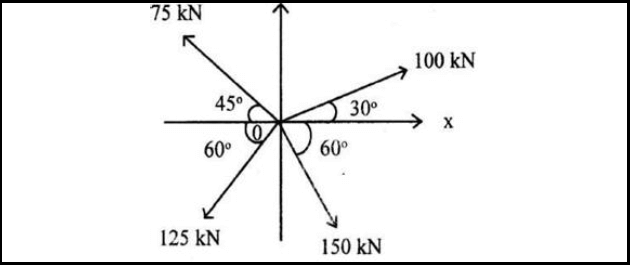
FIGURE 8.1
Xcom = 100 cos 30 + 150 cos 60 – 125 cos 60 – 75 cos 45
= 152,135 N
Ycom = 100 sin 30 + 75 sin 45 – 125 sin 60 – 150 sin 60
= 124,683 N
R = √(?2 + ?²)
R = 196,7 N
Tan θ = y/x
Θ = 124,683/152,135
Θ = 39,336º
Equilibrant = Resultant BUT IN THE OPPOSITE DIRECTION
Equilibrant = 196, 7 N at 219,336º (13)
8.2 Moments: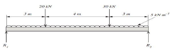
Converting the UDL to Point Load
5 x 10 = 50 kN @ 5m
Calculation of the Reactions Taking moments:
R2 x 10 = (30 x 3) + (50 x 5) + (20 x 7)
= 48 kN
R1 x 10 = (20 x 3) + (50 x 5) + (30 x 7)
= 52 kN (5)
8.3 Stress Calculations
8.3.1 Tensile stress calculations
- F = 12 kN; δ = 24,5 MPa: L = 250 mm: E= 90 PGa
? = ?
?
= 12 x 10 ³/24,5 x 10⁶
A = 4,898 x 10−4m²
? = ??2
? = √4 ?/?
d = 0,02494 m
d = 24,97 mm ≈ 25 mm (5)
8.3.2 The change in length calculations
- ?? = ?; E = 90 GPa; F = 12 Kn; L = 250 mm; Ϭ = 24,5 MPa
?? = ? ? ?
?
= (24,5 x 10⁶ x 0,25) / 90 x 10⁹
= 0,0681 mm (5)
8.4 Stress/Strain diagram:
- A – Limit of Proportionality
- B – Elastic limit
- C – Yield point
- D – Maximum Force/Point
- E – Point of Fracture (5) [33]
QUESTION 9:
MAINTENANCE (SPECIFIC)
9.1 Basic preventative maintenance:
9.1.1 PVC – Polyvinyl chloride (1)
9.1.2 GRP – Glass Fibre Reinforced (1)
9.1.3 LDPE – Polyethylene Low Density (1)
9.2 Reasons for using cutting fluid when working on the centre lathe:
- It prolongs the life of a cutting tool.
- It prevents the shavings or metal chips from sticking and fusing to the cutting tool.
- It will carry away the heat generated by the turning process.
- It flushes away shavings/metal chips.
- It improves the quality of the finish of the turned surface. (Any 1) (1)
9.3 Factors that influence the coefficient of friction:
- Contact pressure
- Surface roughness
- Temperature
- Sliding velocity
- Type of lubrication (Any 3 x 1) (3)
9.4 Reasons for using carbon fibre:
- It light in weight
- It is tougher and stronger
- It can be bent to any shape when heated above 150 ºC. (Any TWO) (2)
9.5 ONE property and ONE use of each composites:
| Composite | Property | Uses | ||
| 9.5.1 | Vesconite |
|
| (2) |
| 9.5.2 | Teflon |
|
| (2) |
| 9.5.3 | Nylon |
|
| (2) |
9.6 Consequences for failure to do maintenance:
- Risk of injury or death (e.g. Failed brakes)
- Financial loss due to damage suffered as a result of part failure
- Loss of valuable production time. (3) [18]
QUESTION 10: JOINING METHODS (SPECIFIC)
10.1 Square Thread Calculations:
10.1.1
- Helix (Tan θ) = ????
??
= 45 / (? x 84)
Tan θ = 0,17
Θ = 9,677º (4)
10.1.2
- Leading Tool Angle = 90 – (Helix + Clearance)
= 90 – (9,677 – 3.)
= 77,323º (3)
10.1.3
- Trailing/Following tool angle = 90 + (Helix – Clearance)
= 90 + (9,677 – 3)
= 96,677º (3)
10.2 Screw thread diagram: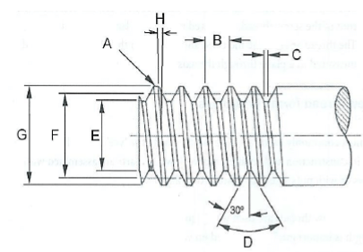
(6)
- A- Crest
- B- Pitch
- C- Root
- D- Thread Angle
- E- Root Diameter
- F- Pitch Diameter
- G- major Diameter
- H- Helix angle
10.3
- Units Conversion: 40,125º
40,125 – 40 = 0,125
0,125 x 60 = 7,5
40º 7’30’’ (2)
[18]
QUESTION 11: SYSTEMS AND CONTROL (DRIVE SYSTEMS) (SPECIFIC)
11.1 Gear drives work on the principle that the turning motion of one gear be transferred to another gear if the gears are mounted close so that they mesh or engage. (2)
11.2 Hydraulic system:
11.2.1 Calculate the Force applied on Piston A.
- da = 28 mm; Db = 148 mm; Xa = 80 mm; Xb = ?
? = ?
?
A = ?Da²/4
= ? (0,028)²/4
= 6,158 x10−4 m²
F = P x A
= 0,4 x 10 ⁶ x 6,158 x 10−4
Force = 246,3 N (5)
11.2.2 Volume displaced in the system:
- Vol@a = Vol@b
Aa x Sla = Ab x SLb
?Da²/4 x 80 = ?Db²/4 SLb
SLB = 2,86 mm (6)
11.3 Functions of a reservoir in a hydraulic system:
- A fluid storage tank
- Promotes air separation from the fluid.
- Supports for the pump and electric motor
- Promotes heat dispersion
- Acts as a base plate for mounting control equipment (Any 2 x 1) (2)
11.4 Belt drive calculations:
- Nmotor x Dmotor = Nblade x Dblade
125 x 1100 = 375 x Dblade
Dblade = 366,667 rpm (3)
11.5 Belt drive advantages:
- They produce less noise and vibrations
- They do not require parallel shafts
- They are simple and cheaper to install compare to other drives
- They do not need lubrication
- Belt drives are very efficient. (2)
11.6 Compound Gear calculations:
11.6.1
- Noutput = ??24 ×?? 20 ×?? 42
?????? ??40 ×?? 48 ×?? 90
N = 24×20×42 × 1440
40×48×90
Noutput = 168 rpm (4)
11.6.2
- VR = ???????
??????
VR = 1440/168
VR = 60 : 7 (3)
11.7 Derivation of Units:
- Torque = Force (F) x Radius (r)
= (N) x (m)
= N.m (1) [28]
TOTAL: 200