Electrical Technology: Digital Grade 12 Memorandum - NSC Exams Past Papers and Memos September 2019 Preparatory Examinations
Share via Whatsapp Join our WhatsApp Group Join our Telegram GroupINSTRUCTIONS TO MARKERS
- All questions with multiple answers imply that any relevant, acceptable answer should be considered.
- Calculations:
2.1 All calculations must show the formulae.
2.2 Substitution of values must be done correctly.
2.3 All answers MUST contain the correct unit to be considered.
2.4 Alternative methods must be considered, provided that the correct answer is obtained.
2.5 Where an incorrect answer could be carried over to the next step, the first answer will be deemed incorrect. However, should the incorrect answer be carried over correctly, the marker has to re-calculate the values, using the incorrect answer from the first calculation. If correctly used, the candidate should receive the full marks for subsequent calculations.
2.6 Markers should consider that candidates' answers may deviate slightly from the marking guideline depending on how and where in the calculation rounding off was used. - These marking guidelines are only a guide with model answers.
- Alternative interpretations must be considered and marked on merit. However, this principle should be applied consistently throughout the marking session at ALL marking centres.
MEMORANDUM
QUESTION 1: OCCUPATIONAL HEALTH AND SAFETY (GENERIC)
1.1
- Faulty tools or equipment ✔
- Poor ventilation ✔
- Poor quality or missing guards on machines ✔
- Excessive noise
- Lack of knowledge of emergency procedures
(Any THREE relevant answers) (3)
1.2 The purpose of the Occupational Health and Safety Act is to provide for the health and safety of:
- Persons at work ✔
- Persons in connection with the use of plant and machinery ✔
- The protection of persons against hazards arising out of the activities of other persons at work
- To establish an advisory council for occupational health and safety and related matters (2)
1.3
- Horseplay ✔
- Running in the workshop ✔
- Throwing things around
- Leaving bags stools or material in walkway
- Spilling a liquid or oil without cleaning
(Any relevant answers) (2)
1.4
- Keep person lying down ✔
- Cover the person to maintain body heat ✔
- Do not move the person in case of neck or spine injuries ✔
- If unconscious, put them on their side (recovery position)
(Any THREE relevant answers) (3) [10]
QUESTION 2: SWITCHING CIRCUITS (GENERIC)
2.1
2.1.1 Mono-stable multivibrator ✔ (1)
2.1.2
- It has ONE input ✔
- It has ONE stable state ✔ (2)
2.1.3
- The RC network in this circuit is the timing component of this circuit ✔
- The values of the resistor and the capacitor determines for how long the circuit will be in ‘HIGH’, ✔state before it reverts back to its stable ‘LOW’ state ✔ (3)
2.1.4
- By changing R2 from a fixed resistor value to a variable resistor ✔
- By changing the value of C2 from a fixed value capacitor to a variable capacitor ✔
- By changing both R2 and C2 from fixed values ✔ to variable values ✔ (4)
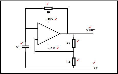
2.1.5
- When the circuit is in resting condition, the negative voltage of –Vref on the inverting input serves to hold this inverting input low ✔
- This will cause the Op-Amp to saturate and the output to rise to + 15 V ✔
- The capacitor, C, charges up with the top plate to + 15 V, and the bottom plate to 0 V ✔
- When the capacitor is charged, no current flows through R as there is no voltage over it. This holds the non-inverting input at 0 V ✔
- A positive trigger pulse larger than Vref applied to the inverting input terminal will raise the inverting input potential above the 0V of the non-inverting input ✔
- The Op-Amp will now saturate and the output will go to -15 V ✔
- The capacitor will now immediately start discharging through the resistor ✔
- The lower plate of the capacitor rises and when the voltage is less negative than Vref, the output changes to +15 V again ✔ (8)
2.1.6 Debouncing ✔ (1)
2.2
2.2.1 At one end the potentiometer will be connected to 0 Ω. ✔ R1 will prevent the full supply flowing to pin 6 and 7, when the potentiometer is in the 0 Ω position ✔ (2)
2.2.2
- By changing the value of C1 ✔
- By changing the value of R3 ✔ (2)
2.2.3 The time period will increase (1)
2.3
(8)
2.4
(6)
2.5 The time lag (delay) between cause ✔ and effect ✔ (2)
2.6
- First stage of many radio receivers to clean up noise ✔
- To eliminate switch bounce in digital circuits ✔
- Varying input waveforms, for instance sine wave changed into square wave or rectangular wave
- Signal recovery after experiencing severe distortion (2)
2.7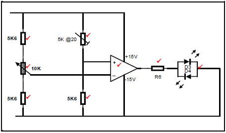
(8)
2.8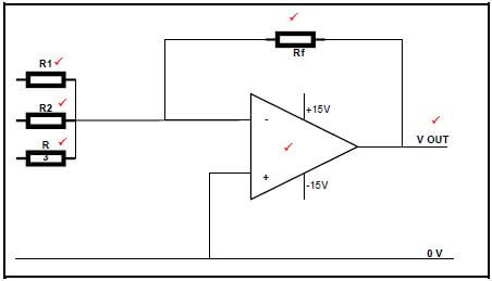
(6)
2.9 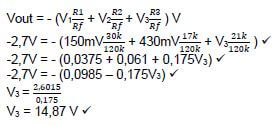
(4) [60]
QUESTION 3: SEMI-CONDUCTOR DEVICES (SPECIFIC)
3.1
- Input stage (Differential amplifier) ✔
- Intermediate stage (High gain differential amplifier) ✔
- Common Collector (Darlington Pair) output stage ✔ (3)
3.2 The ability of the Op-Amp ✔ to suppress a common-anode ✔ is called the common-mode-rejection ratio (2)
3.3
3.3.1 Non-inverting Op-Amp (1)
3.3.2
- AV = 1 + Rf
Rin
= 1 + 1000
1900✔
= 1 + 0,526
= 1,526 ✔ (2)
3.4
- Basic timing function, e.g. turning a light on or off after a period of time ✔
- Pulse oscillation and wave generation ✔
- Creating a flashing warning light ✔
- Digital logic probes
- Producing musical notes of specific frequencies
- Temperature measurement
- Controlling the positioning of servo devices (3)
3.5
- Operate on supply voltages between +5 V to +18 V ✔
- The maximum current it can either sink or source is 200 mA ✔ (2)
3.6 In the construction of this IC there are three series connected resistors of identical value (5 kΩ). ✔ These resistors divide ✔ the voltages to 2/3 and 1/3 of the supply voltage ✔ (3)
3.7
3.7.1 Threshold ✔ (1)
3.7.2
- This pin sets off the IC
- It is an active low trigger ✔
- When the voltage on pin 2 is less than 13of the supply, the output goes high ✔
- When the voltage on pin 2 is higher than 23of the supply, the output will go low ✔
- If connected to ground, the output will go ‘high’ and remain ‘high’ (3) [20]
QUESTION 4: DIGITAL AND SEQUENTIAL DEVICES (SPECIFIC)
4.1 The anodes of all 8 LEDs are connected together ✔on the positive voltage rail ✔ (2)
4.2

(4)
4.3
- Light waves travel naturally in both the vertical and the horizontal planes ✔
- When the light passes through a filter which only allows a single plane of light to pass through and block the other plane of light, ✔
- it is called polarisation ✔ (3)
4.4
4.4.1 Encoder ✔ (1)
4.4.2
INPUTS | OUTPUTS ✔ | |
0 | A1 | A0 |
0 | 0 ✔ | |
1 | 0 | 1 ✔ |
2 | 1 | 0 ✔ |
3 | 1 | 1 ✔ |
(5)
4.4.3 An encoder accepts the input data in a decimal format ✔and converts it to binary format ✔ (2)
4.5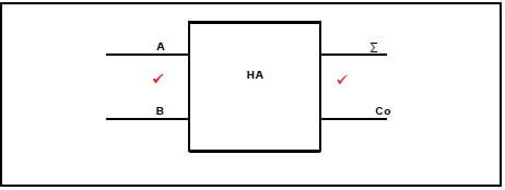
(2)
4.6.2 C 1
4.6
4.6.1 Full adder ✔ (1)
4.6.2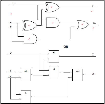
(8)
4.7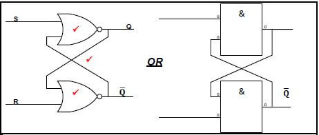
(3)
4.8
MODE OF OPERATION | INPUTS | OUTPUTS | ||
ILLEGAL | S | R | Q1 | Q2 |
0 | 0 | 0 | 0 ✔ | |
SET | 0 | 1 | 1 | 0 ✔ |
RESET | 1 | 0 | 0 | 1 ✔ |
HOLD | 1 | 1 | NO CHANGE ✔ | |
(4)
4.9 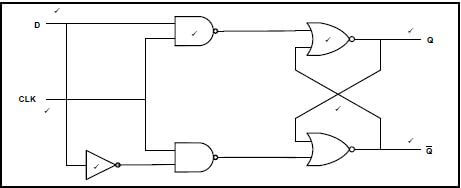
(8)
OR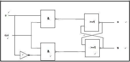
4.10 When a circuit reacts to the positive (rising) edge ✔ of the pulse going from 0 to 1 ✔ (2)
4.11
- The UP/DOWN counter control is dictated by the HIGH “1” or LOW “0” on the control line to determine the direction of counting
- If set to UP, the control line is high ✔
- This will enable the upper 2 AND gates to become active when they get a high from either FF0 or FF1 outputs
- Once activated, the AND gate between FF0 and FF1 will enable the high “1” output from Q0 to both J and K inputs of FF1 ✔
- Likewise, a high “1” output from FF1 will enable the 2nd AND gate to pass a high “1” to the J and K inputs of FF2 ✔
- In this way the circuit operates as a normal UP counter, advancing its count from 010 to 710 ✔
- If set to DOWN, the control line is set to LOW “0”. This will disable the upper 2 AND gates while presenting a LOW “0” at the input of the invertor
gate ✔ - A LOW “0” input will cause a HIGH “1” output at the invertor ✔
- This HIGH “1” will enable the 2 lower AND gates ✔
- When they receive a HIGH “0” from either of the 2 flip-flops, FF0 and FF1, they will place a HIGH “0” on the inputs of the next flip-flops ✔
- This enables them to toggle at the next clock pulse
- This circuit then operates as a normal down counter (8)
4.12 This is a counter which has been modified to stop its count at a pre-set value ✔ before reaching the maximum count ✔ (2) [55]
QUESTION 5: MICROCONTROLLERS (SPECIFIC)
5.1 It is an independent device, ✔a computer on a chip, that can perform a limited range of functions ✔without needing to rely on other chips or devices ✔ (3)
5.2
- Alarm monitoring and warning devices ✔
- Fire detection and safety devices ✔
- Temperature sensing and control
- Light sensing and control (2)
5.3 It has a very low output current, ✔only a few milli-amps, and therefore requires interfacing circuitry to drive higher current loads ✔ (2)
5.4
5.4.1 Central Processing Unit is responsible for interpreting ✔ and executing the stored instructions from the ROM program ✔ (2)
5.4.2 Input/Output communication lines enable the microprocessor to communicate ✔ with the outside world via interface connections as tracks on a board ✔ (2)
5.5 This is a single chip containing the entire processor ✔ (1)
5.6
5.6.1 Contains the address and status of the next instruction for processing. ✔Also tells the processor what the next instruction is. ✔ It also keeps count of the number of instructions that have been
executed ✔ (3)
5.6.2 Stores a copy of the current instruction been executed ✔ (1)
5.7
- RAM can both read data and have it written to ✔
- It can hold programmes, operating systems and data required by the system ✔
- It is known as a volatile memory as it loses all data stored when it loses power ✔
- RAM stores all the data that is required to be processed by the CPU during the execution of programmes ✔
- RAM consists of a list of addresses and in each address is a piece of data ✔ (5)
5.8
- Control bus ✔
- Data bus ✔
- Address bus ✔ (3)
5.9 A set of rules and regulations that allow 2 electronic devices ✔ to connect to exchange data and information between each other ✔ (2)
5.10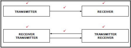
(6)
5.11
- No need for a synchronous clock pulse between sender and receiver ✔
- Peer-to-peer system where data can be transferred in both directions between the two devices ✔ (2)
5.12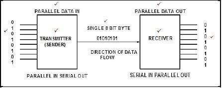
(7)
5.13
- Supports higher speed full duplex communication ✔
- Draws very little power ✔
- Can operate at extremely high speeds (millions of bits per second) (2)
5.14
5.14.1 Start/finish instruction ✔ (1)
5.14.2 Decision instruction ✔ (1)
5.15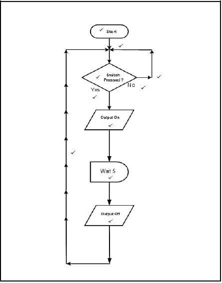
(10) [55]
TOTAL: 200