Electrical Technology: Power Systems Grade 12 Questions - NSC Exams Past Papers and Memos September 2019 Preparatory Examinations
Share via Whatsapp Join our WhatsApp Group Join our Telegram GroupINSTRUCTIONS AND INFORMATION
- This question paper consists of SIX questions.
- Sketches and diagrams must be large, neat and fully labelled.
- Show ALL calculations and round off answers correctly to TWO decimal places.
- Number the answers correctly according to the numbering system used in this question paper.
- You may use a non-programmable calculator.
- Show the units for ALL answers of calculations.
- A formula sheet is provided at the end of this question paper.
- Write neatly and legibly.
QUESTIONS
QUESTION 1: OCCUPATIONAL HEALTH AND SAFETY (GENERIC)
1.1 Name THREE unsafe conditions that cause most accidents in the workshop. (3)
1.2 Explain the purpose of the Occupational Health and Safety Act. (2)
1.3 Give TWO unsafe acts in a school workshop that can cause an accident. (2)
1.4 Describe THREE standard treatments for electric shock after the electricity has been removed. (3) [10]
QUESTION 2: RLC CIRCUITS (GENERIC)
2.1 Define the term Q-factor with reference to a parallel resonant circuit. (2)
2.2 State THREE factors that will affect the impedance of an RLC circuit. (3)
2.3 List THREE characteristics of a series resonance frequency. (3)
2.4 Refer to the circuit diagram FIGURE 2.4 below and answer the questions that follow.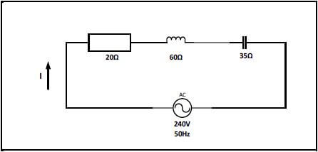
FIGURE 2.4: RLC CIRCUIT
Given:
R = 20 Ω
XL = 60 Ω
XC = 35 Ω
VS = 240 V
F = 50 Hz
2.4.1 Calculate the total impedance of the circuit. (3)
2.4.2 Calculate the power factor of the circuit. (3)
2.4.3 State whether the power factor is leading or lagging. (1)
2.4.4 Explain what happens to the Q-factor of an RLC circuit if the values of R, L and C are doubled. (3)
2.5 A parallel RLC circuit consists of a resistor with a resistance of 120 Ω, an inductor with an inductive reactance of 160 and a capacitor with a capacitive reactance of 220 Ω. All are connected across a 100 V / 50 Hz supply.
2.5.1 Draw the circuit diagram that represents the above information. (3) Calculate:
2.5.2 The current through the resistor (3)
2.5.3 The current through the inductor (3)
2.5.4 The current through the capacitor (3)
2.5.5 The total current of the circuit (3)
2.5.6 The phase angle (3)
2.5.7 Draw the phasor diagram that represents the current and the voltage. (4) [40]
QUESTION 3: THREE-PHASE AC GENERATION (SPECIFIC)
3.1 State the purpose of the switchgear used in substations. (2)
3.2 Draw a labelled phasor diagram of a balanced three-phase system. (4)
3.3 The following values were obtained by using the two-wattmeter method.
PT = 4kW
W1 = −2500 W
W2 = ?
3.3.1 Determine the reading of W2. (3)
3.3.2 Explain why digital electronics form the basis for meters used today. (2)
3.4 State TWO disadvantages of a three-phase system when compared to a single phase system. (2)
3.5 Mention THREE types of reactive elements introduced to improve a low power factor. (3)
3.6 A three-phase delta connected load is supplied by a 300 kVA generator with a line voltage of 250 V. The power factor is 0,866 lagging.
Given:
S = 300 kVA
VL = 250 V
cos θ = 0,866
Calculate:
3.6.1 The phase voltage (2)
3.6.2 The line current to the delta connected load (3)
3.6.3 The active power (3)
3.6.4 The reactive power (4)
3.7 Define efficiency of a three-phase system. (2) [30]
QUESTION 4: THREE-PHASE TRANSFORMERS (SPECIFIC)
4.1 List THREE factors that could lead to excessive heating in transformers. (3)
4.2 The table below represents the information available on three single-phase transformers. Study the table and answer the questions that follow.
CHARACTERISTICS | Transformer A | Transformer B | Transformer C |
Frequency | 50 Hz | 50 Hz | 60 Hz |
Voltage | 240 V – 24 V | 240 V – 24 V | 110 V – 24 V |
Current | 15 A | 15 A | 15 A |
Power | 360 VA | 360 VA | 360 VA |
4.2.1 State, with reasons, if the transformers are suitable to be connected as three-phase transformers. (3)
4.2.2 Determine if transformer C is suitable for operation on a standard South African supply. (2)
4.2.3 Explain what would happen if transformer A is connected to a 240 V direct current supply. (3)
4.3 Name TWO losses that occur in the iron cores of transformers. (2)
4.4 Write down TWO methods used when connecting three single-phase transformers to operate as a three-phase transformer. (2)
4.5 Explain what could happen if large transformers did not have cooling systems. (2)
4.6 A three-phase transformer with a primary line voltage of 11 kV is connected in delta-delta to a 25 kW load with a power factor of 0,8. The secondary line voltage is 250 V and the losses amount to 2,8 kW.
Given:
VLP = 11 kV
POUT = 25 kW
cos θ = 0,8
VLS = 250 V
Losses = 2,8 kW
Calculate:
4.6.1 The primary phase voltage (2)
4.6.2 The secondary phase current (6)
4.6.3 The efficiency (3)
4.6.4 The turns ratio (2) [30]
QUESTION 5: THREE-PHASE MOTORS AND STARTERS (SPECIFIC)
5.1 Give TWO reasons why squirrel cage motors are more widely used in industrial applications than slip ring induction motors. (2)
5.2 Answer the following with reference to the rotor of an induction motor:
5.2.1 Explain the term cogging of the rotor. (2)
5.2.2 State how cogging is overcome. (1)
5.3 Calculate the rotor speed of a squirrel cage rotor if the synchronous speed is 3 600 rpm and the slip is 4,5%.
Given:
S = 4,5%
NS = 3600 rpm (3)
5.4 State the purpose of contactors used in starter circuits. (2)
5.5 Refer to the control circuit in FIGURE 5.5 and answer the questions that follow.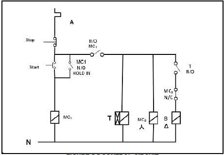
FIGURE 5.5 CONTROL CIRCUIT
5.5.1 Identify the control circuit in FIGURE 5.5. (1)
5.5.2 Supply labels to the contacts labelled A and B. (2)
5.5.3 Explain the functions of the following contacts:
5.5.3.1 MC1(N/O) hold in (1)
5.5.3.2 MC2(N/C) (1)
5.5.3.3 T(N/O) (1)
5.5.4 Explain what occurs when the circuit is energised and the start button is pressed. (5)
5.6 A 415 V three-phase motor is rated at 15 kW and has a power factor of 0,75. It draws a current of 30 A when connected in delta to the supply.
Given:
POUT = 15 kW
VL = 415 V
IL = 30 A
cos θ = 0,75
Calculate:
5.6.1 The phase voltage of the motor coils (3)
5.6.2 The input power to the motor (3)
5.6.3 The efficiency of the motor (3) [30]
QUESTION 6: PROGRAMMABLE LOGIC CONTROLLERS (PLCs) (SPECIFC)
6.1 Define a programmable logic controller (PLC). (3)
6.2 Discuss how cost is an advantage to a PLC when compared to hard wired relay systems. (2)
6.3 Refer to FIGURE 6.3 below and answer the questions that follow. 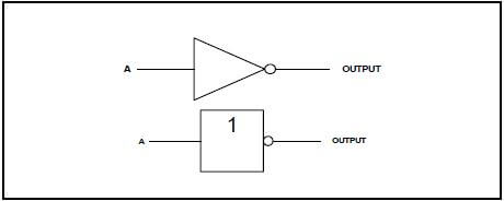
FIGURE 6.3
6.3.1 Identify the logic gate shown in FIGURE 6.3. (1)
6.3.2 Draw the truth table for the gate shown in FIGURE 6.3. (2)
6.3.3 Draw the ladder logic diagram. (2)
6.4 State THREE applications of proximity sensors. (3)
6.5 Describe in detail a latch in a circuit. (2)
6.6 List THREE applications of regenerative braking. (3)
6.7 Answer the following questions with reference to Variable Speed Drives (VSD):
6.7.1 State TWO advantages of using variable speed drives. (2)
6.7.2 Explain the function of the microprocessor. (5)
6.7.3 Describe how the vector drives perform their function. (3)
6.7.4 Draw a neat, labelled circuit diagram showing a VSD connected to a three-phase motor. (5)
6.7.5 Discuss in detail the THREE parts a VSD consists of. (8)
6.8 Refer to FIGURE 6.8 below and answer the questions that follow.
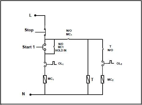
FIGURE 6.8
6.8.1 Describe the sequence after start 1 has been pressed. (5)
6.8.2 Draw the ladder diagram that executes the same function as the circuit diagram in FIGURE 6.8. (11)
6.8.3 Explain what would happen if N/O MC1 HOLD IN was not connected in the circuit. (3) [60]
TOTAL: 200