ELECTRICAL TECHNOLOGY (POWER SYSTEMS) GRADE 12 MEMORANDUM - NSC EXAMS PAST PAPERS AND MEMOS MAY/JUNE 2021
Share via Whatsapp Join our WhatsApp Group Join our Telegram GroupELECTRICAL TECHNOLOGY (POWER SYSTEMS)
GRADE 12
NATIONAL SENIOR CERTIFICATE EXAMINATIONS
MAY/JUNE 2021
INSTRUCTIONS TO THE MARKERS
- All questions with multiple answers imply that any relevant, acceptable answer should be considered.
- Calculations:
2.1 All calculations must show the formulae.
2.2 Substitution of values must be done correctly.
2.3 All answers MUST contain the correct unit to be considered.
2.4 Alternative methods could be considered, provided that the correct answer is obtained.
2.5 Where an incorrect answer could be carried over to the next step, the first answer will be deemed incorrect. However, should the incorrect answer be carried over correctly, the marker has to re-calculate the values, using the incorrect answer from the first calculation. If correctly used, the candidate should receive the full marks for subsequent calculations. - This memorandum is only a guide with model answers. Alternative interpretations must be considered and marked on merit. However, this principle should be applied consistently throughout the marking session at ALL marking centres.
QUESTION 1: OCCUPATIONAL HEALTH AND SAFETY
1.1 'Safe' means free from any hazard. ✓ (1)
1.2
Discipline. ✓
Sense of teamwork. ✓
Emphasis on quality.
Integrity.
Sense of responsibility. (2)
1.3
The use of power tools. ✓
The handling of hand tools.
The use of etching acid and other chemicals. (1)
1.4
Poor ventilation reduces the correct amount of oxygen ✓ which might lead to drowsiness. ✓
Covid-19 protocols also refer to proper ventilation that must be adhered to. (2)
1.5
To take reasonable care for the health and safety of himself/herself and others who may be affected by his/her act. ✓
Cooperate with the employer or persons to enable that any duty given by the employer to the employee shall be performed or complied with according to the requirements and procedures. ✓ (2)
1.6 Human rights ensure human dignity ✓ and that people are treated with respect and not exploited. ✓ (2)
[10]
QUESTION 2: RLC CIRCUITS
2.1
2.1.1 Phase angle is the shift in phase between the supply voltage ✓ and the current ✓ in a circuit which contain reactances and resistances. (2)
2.1.2 Capacitance is the ability of a capacitor to store an electric charge.✓ (1)
2.2
It will affect the phase angle. ✓
It will oppose the current flow in the circuit. ✓
Lenz’s law states that when alternating current flows through an inductor, a back emf is set up which is opposite to the applied voltage. (2)
2.3
2.3.1
XL = 2 x π x f x L
= 2 x π x 60 x 300 x 10-3
= 113,10Ω
(3)
2.3.2
Z = √R2 + (XL - XC)2
= √302 + (113,10 - 30,32)2
= 88,05 Ω
(3)
2.3.3 Inductive circuit. ✓ The inductive reactance is greater than the capacitive reactance. ✓ (2)
2.4
2.4.1
![]()
=300/50
=6A(3)
2.4.2
![]()
=300/3
=100Ω
(3)
2.4.3
IT= √IR2 + (IL-IC)2
= √42 + (3-6)2
=5A
(3)
2.4.4
![]()
=Cos-1 4/5
=36,87
(3)
2.5
2.5.1 Impedance. ✓ (1)
2.5.2 Capacitive reactance is greater ✓ than the inductive reactance.✓ (2)
2.5.3
The inductive reactance is represented by a straight line because it is directly proportional to the frequency ✓ of the supply voltage and the capacitive reactance is represented by the curved line because it is indirectly proportional to the frequency of the supplied voltage.✓
The Reactance value of a capacitor has a very high value at low frequencies but quickly decreases as the frequency across it increases. (2)
2.5.4
fr = 1
2π√LC
= 1
2π √2,12 x 1,47 x 10-6
= 90,16 Hz
(3)
2.5.5
Tuning circuits. ✓
Radio circuits.
Oscillator circuits.
TV circuits.
Filter circuits.
Band pass filter. (1)
2.6
2.6.1 The higher the value of the Q-factor the greater the value of the current flow.✓ (1)
2.6.2
Half power points are the upper and lower cut off frequencies in a circuit.✓
Point at which the output power has dropped to half of its peak value, at a level of approximately -3db. (1)
2.6.3
- The value of the series resistor.✓
- The inductor/capacitor (L/C) ratio. ✓ (2)
2.6.4 As the Q factor of the circuit is lowered, its selectivity decreases✓ and its bandwidth increases.✓ (2)
[40]
QUESTION 3: THREE-PHASE AC GENERATION
3.1
3.1.1 Efficiency of a three-phase system is the ratio of the output power ✓ to the input power. ✓ (2)
3.1.2 Power factor correction is the process of introducing reactive elements ✓ to improve the power factor. ✓ (2)
3.2
- Installations costs are very high. ✓
- Not available everywhere. ✓
- Not suitable for most residential applications. ✓
- Appliances operating with three phase supply are expensive. (3)
3.3
3.3.1 The value of the phase voltage (Vph) is equal to the value of the line voltage (VL) ✓ (Vph = VL) (1)
3.3.2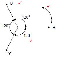
NOTE:
- 1 mark for rotation
- 1 mark for the correct sequence
- 1 mark for the phase angle
(3)
3.4 The generated electricity is less at the point of distribution because of the copper losses ✓ occurring inside the transmission lines ✓ and transformers during power transmission. (2)
3.5
3.5.1
The current through a capacitor leads the voltage by 90 degrees ✓ and it will as a result reduce ✓ the inductive lagging current.
Capacitors draw leading currents which neutralise the lagging currents. (2)
3.5.2
- Reduced supply current. ✓
- Thinner supply conductors are required ✓
- Reduced cost of thinner conductors
- Reduced maintenance of supply equipment (2)
3.6
3.6.1
![]()
= 380
√3
=219,39 V
(3)
3.6.2
P = S x Cos θ
=250000 x 0,9
=225 000 W
=225 kW✓
(3)
3.6.3
θ cos-1 (0,9)
25,84°
Q = S x sinθ
=250000 sin (25,84)
=108964,88VA
=109 kVA✓
(5)
3.7 The kilowatt-hour meter is used to measure the energy ✓ consumed by a load. ✓ (2)
[30]
QUESTION 4: THREE-PHASE TRANSFORMERS
4.1
- Air Forced. ✓ (AF)
- Air Natural. ✓ (AN) (2)
4.2
- Losses ✓
- Transformer loading (1)
4.3
- Assemble or modify the circuit ONLY when the supply is OFF. ✓
- Do not switch the circuit ON before a supervisor (teacher) has inspected and is satisfied. ✓
- NEVER touch any bare electric wire or terminal.
- Exercise extreme care during experiments.
- After a practical, wait for the transformer to cool down before returning it back to the store room.
- Be very careful of the secondary terminals of a live open circuit transformer. Even after switch off, the transformer can store very high (fatal) voltages on the secondary coil.
- Earth the metal parts of a transformer. (2)
4.4
4.4.1 Delta/star ✓ (1)
4.4.2
Industry or commercial sites where both single and three-phase power is needed. ✓
Domestic distribution networks where only single phase power is needed. ✓ (2)
4.4.3 It is a step-down ✓ transformer because the turns ratio is 5:1. ✓ (2)
4.5
4.5.1 To supply the same loads, single phase transformers become more expensive ✓ than three phase transformers. (1)
4.5.2 Three phase transformers are more efficient ✓ than single phase transformers. (1)
4.6
- When a fault occurs inside a transformer the oil heats up and gas forms inside the oil ✓ depending on the severity of the fault.
- The heated oil and gas flows from the main tank though the Buchholz relay into the conservator tank. ✓
- A continuous slow formation of gas will cause the Buchholz relay to activate the alarm system. ✓
- The alarm indicates that there is a small fault in the system that needs close monitoring. ✓
- The moment that there is a severe fault, a big amount of gas is formed and the flow rate is also increased. ✓
- This increased gas formation will immediately activate the Buchholz relay isolating the transformer from the supply ✓ and protecting it from the any further damage. (6)
4.7
4.7.1
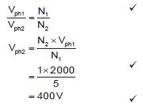
(3)
4.7.2
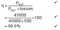
(3)
4.7.3
Cosθ = P/S
= 45000/ 50000
= 0,9✓
(3)
4.7.4
IL2= P
√3 x VL2 x cosθ
= 45000
√3 x 400 x 0,9
= 72,17 A ✓
OR
IL2 = S
√3 x VL2
= 50000
√3 x 400
=72,17 A
[30]
QUESTION 5: THREE-PHASE MOTORS AND STARTERS
5.1
5.1.1
A – End ring ✓
B – Bearing ✓ (2)
5.1.2
- Less maintenance due to no brushes or slip rings. ✓
- They are less prone to explosions because any sparks are eliminated due to the absence of brushes and slip rings. (1)
5.1.3
- It helps in the reduction of magnetic hum. ✓
- It helps to avoid cogging. (locking tendency of the rotor)
- It increases the effective ratio of transformation between stator and rotor.
- It causes an increased rotor resistance due to comparatively lengthier rotor conductor rods.
- Increased slip for a given torque. (1)
5.2
5.2.1 Slip is the difference ✓ between the synchronous speed ✓and the rotor speed of an induction motor expressed in a percentage. (2)
5.2.2 Commissioning is when the electric motor is connected to the power supply and the load ✓ after all inspections (electrical and
mechanical) have been completed. ✓ The motor is certified and ready to be used. (2)
5.3 Inspect the:
- Mounting bolts to check if it is properly tightened. ✓
- Endplates to check if it is securely fastened.
- Frame for any cracks.
- Shaft for any play on it.
- Shaft if it turns freely by hand.
- Cooling fan if it is intact.
- Bearings for smooth movement when turned by hand.
- Bearing housings for excess grease or dust. (1)
5.4
5.4.1
poles per phase = 12/3 = 4
pole pair per phase (p)= 4/2 = 2 pole pairs✓
(2)
5.4.2
ns= f x 60
p
50 x 60
2
=1500rom
1500 rpm ✓
(3)
5.4.3
nr = ns (ns x slip)
= 1500 - (1500 x 3/100)
1455 rpm ✓
(3)
5.4.4
(3)
5.5
5.5.1 Forward reverse control circuit. ✓ (1)
5.5.2
- OLN/C will open ✓ the moment the current surpasses the preset rated current, stopping the current flow to MC1, ✓ and thus stopping the motor.(2)
- MC2N/O is the retain contact ✓ for the reverse contactor ✓ ensuring that current continues to flow to MC2, after the start button is released.
(2)
5.5.3 MC1 N/C is used as an interlocking contact. ✓ When MC1 (forward) is activated MC1N/C will open ensuring that MC2 cannot be activated when MC1 is active. ✓ (2)
5.6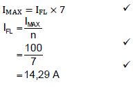
(3)
[30]
QUESTION 6: PROGRAMMABLE LOGIC CONTROLLERS (PLCs)
6.1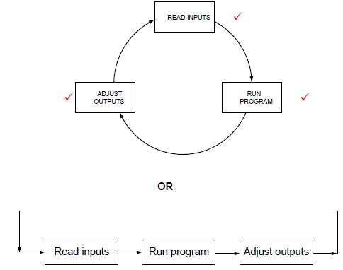
(3)
6.2
- A PLC system would use fewer relays, cam controllers, timers, and counters. ✓
- Control panels would not have to be re-wired when production models were changed. ✓ (Hardware)
- A PLC system physically takes up less space than Hardwired systems.
- A PLC system is cheaper when compared to large bulky relays and their cabinets.
- System upgrade is easier and faster. (Software) (2)
6.3 The PLC wiring and connections must be checked before switching on to ensure that:
- There is no incorrect wiring ✓
- There are no loose connections ✓ (2)
6.4
- All processing is done at low voltages and therefore safer. ✓
- The normal operation of a plant can be observed electronically on a monitor keeping the observer away from dangerous machines. ✓
- All operations are shown on the interface as machines turned on and faulty contactors can be located without having to fault find on a live system.
- Part of a plant can be switched off digitally for repairs to be done. (2)
6.5
6.5.1
- The unit that performs all logic operations internally. ✓
- It runs the ladder program. ✓ (2)
6.5.2 Soft-wired systems perform many functions digitally ✓ to reduce the amount of wiring in a circuit. ✓ (2)
6.5.3
- PLC software is a program that is written into the unit to control its functions. ✓
- PLC software is the program used to compile the ladder logic program.(1)
6.6
- An analogue signal is a continuously changing signal. ✓
- A digital signal is a signal with a number of discrete steps. ✓ (2)
6.7
6.7.1
- Markers are used to hold data ✓ in the PLC program.
- They can be switched on or off and control other programs or output devices.
- They can be used to indicate when a certain stage in a program is complete.
- They can be used to indicate the start of the timing processor’s next event. (1)
6.7.2
- The contactor on the program drives the coil on the relay contact. ✓
- It can be programmed to be normally closed or normally open contacts.
- They can control single phase or three phase contactors. (1)
6.8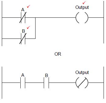
(3)
6.9
6.9.1 A sensor is a device that detects and converts an environmental condition ✓ into an electrical signal ✓ that can be used by another device for a particular purpose. (2)
6.9.2
- Temperature sensor ✓
- Light sensor ✓
- Overload sensor.
- Level sensor. (2)
6.9.3
- To detect the proximity of an object in relation to its distance ✓
- Used to measure rotating speed ✓ (2)
6.10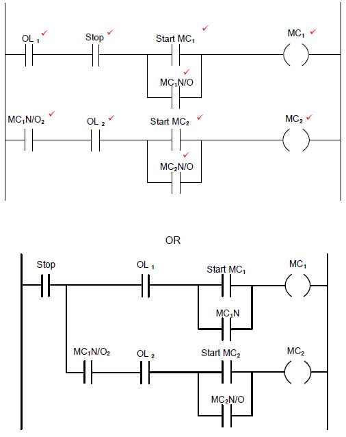
(10)
6.11
- ON-delay ✓
- OFF-delay ✓
- ON/OFF-delay (2)
6.12
- When the start button is pressed, coil MC will be energised,✓
- Contact MCN/O1 will close ✓ (Retention)
- Contact MCN/O2 will close ✓ and the lamp will be 'ON'.
- The lamp will remain ON, until the stop button is pressed. ✓ (4)
6.13
- Transistor ✓
- Relay ✓(2)
6.14
6.14.1
- Regenerative braking block diagram. ✓
- VSD control system with a load (1)
6.14.2 The braking resistor is connected to the circuit to dissipate excessive regenerated energy. ✓ The resister heats up and emits heat. ✓
It protects the DC capacitors of a VSD from being overloaded. (2)
6.15 The regenerated energy can be converted ✓ into another form of energy ✓ where it is stored and used when necessary. ✓ (3)
6.16
6.16.1
- AC to DC Converter ✓
- Rectifier (1)
6.16.2 Capacitors ✓ (1)
6.16.3
- The inverter, inverts the DC voltage back to AC voltage at a different frequency. ✓ by switching the Insulated Gate Bipolar Transistor ON and OFF at a high frequency. ✓
- The ON and OFF times (width of the pulses) are carefully controlled (PWM) with three pairs of switches. ✓
- For every pair of switches, one switch controls the positive✓ part of the output voltage, the other switch controls the negative part of the output voltage. ✓
- The frequency of switching controls the rotation speed. (5)
6.16.4
- Energy savings ✓
- Better speed control of motors ✓
- Better power factor
- Smooth starting of motors (2)
[60]
TOTAL: 200