ELECTRICAL TECHNOLOGY (POWER SYSTEMS) GRADE 12 QUESTIONS - NSC EXAMS PAST PAPERS AND MEMOS MAY/JUNE 2021
Share via Whatsapp Join our WhatsApp Group Join our Telegram GroupELECTRICAL TECHNOLOGY (POWER SYSTEMS)
GRADE 12
NATIONAL SENIOR CERTIFICATE EXAMINATIONS
MAY/JUNE 2021
INSTRUCTIONS AND INFORMATION
- This question paper consists of SIX questions.
- Answer ALL the questions.
- Sketches and diagrams must be large, neat and FULLY LABELLED.
- Show ALL calculations and round off answers correctly to TWO decimal places.
- Number the answers correctly according to the numbering system used in this question paper.
- You may use a non-programmable calculator.
- Calculations must include:
7.1 Formulae and manipulations where needed
7.2 Correct replacement of values
7.3 Correct answers and relevant units where applicable - A formula sheet is attached at the end of this question paper.
- Write neatly and legibly.
QUESTION 1: OCCUPATIONAL HEALTH AND SAFETY
1.1 Define the term safe with reference to the Occupational Health and Safety Act, 1993 (Act 85 of 1993).(1)
1.2 State TWO characteristics or moral principles related to work ethics. (2)
1.3 Give ONE category/example of a dangerous practice in a workshop. (1)
1.4 Explain why poor ventilation is an unsafe condition in the workshop. (2)
1.5 Name TWO general duties of employees at the workplace.(2)
1.6 Explain the need for human rights in the workplace. (2)
[10]
QUESTION 2: RLC CIRCUITS
2.1 Define the following terms with reference to RLC circuits:
2.1.1 Phase angle (2)
2.1.2 Capacitance (1)
2.2 Explain the effect Lenz's law has on an inductor in an RLC circuit connected across an alternating supply voltage. (2)
2.3 The series RLC circuit in FIGURE 2.3 below consists of a resistor with a resistance of 30 Ω, an inductor with an inductance of 300 mH and a capacitor with a capacitive reactance of 30,32 Ω. The components are all connected across the supply voltage of 80 V/60 Hz AC with a total current of 2,55 A flowing through the circuit. Answer the questions that follow.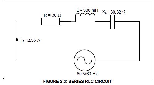
Given:
R = 30 Ω
L = 300 mH
XC = 30,32 Ω
IT = 2,55 A
VT = 80 V
f = 60 Hz
2.3.1 Calculate the inductive reactance of the circuit. (3)
2.3.2 Calculate the total impedance of the circuit. (3)
2.3.3 State whether the circuit is capacitive or inductive. Give a reason to substantiate your answer. (2)
2.4 FIGURE 2.4 below shows a parallel RLC circuit that consists of a 75 Ω resistor, an inductor with unknown inductance value and a capacitor with
a capacitive reactance of 50 Ω, all connected across 300 V AC supply voltage. The current flowing through the resistor is 4 A and the current flowing
through the inductor is 3 A. Answer the questions that follow.
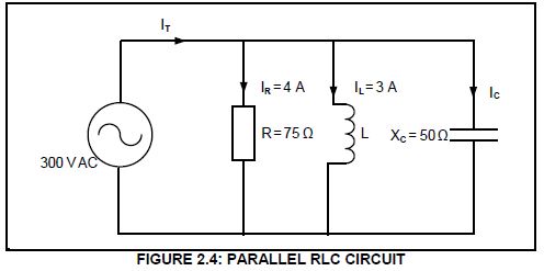
Given:
VT = 300 V AC
XC = 50 Ω
R = 75 Ω
IR = 4 A
IL = 3 A
2.4.1 Calculate the value of the current through the capacitor. (3)
2.4.2 Calculate the value of the inductive reactance. (3)
2.4.3 Calculate the value of the total current. (3)
2.4.4 Calculate the phase angle. (3
2.5 Refer to FIGURE 2.5 below and answer the questions that follow.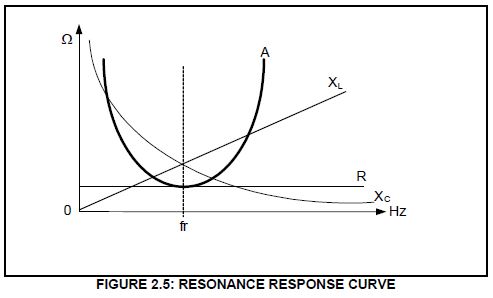
2.5.1 Name the response curve represented by A. (1)
2.5.2 Compare the magnitude of the reactance values (XL and XC) below the resonant frequency. (2)
2.5.3 Explain why the inductive reactance in FIGURE 2.5 is represented by a straight line and the capacitive reactance is represented by a curved line.(2)
2.5.4 Calculate the resonant frequency of a series RLC circuit with the following component values: a resistor with a resistance of 20 Ω, capacitor with a capacitance of 1,47 μF and an inductor with an inductance of 2,12 H connected across an AC supply.
Given:
R = 20 Ω
C = 1,47 μF
L = 2,12 H
(3)
2.5.5 Name ONE application of the circuit in QUESTION 2.5.4. (1)
2.6 Refer to FIGURE 2.6 below and answer the questions that follow.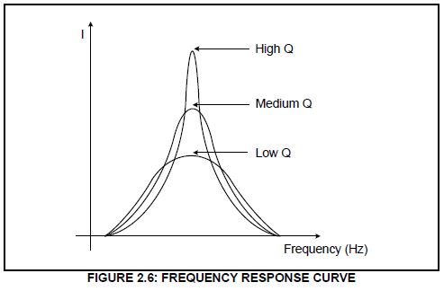
2.6.1 Explain how the value of the Q-factor affects the value of the current. (1)
2.6.2 Define the term half power points. (1)
2.6.3 When choosing a component, name TWO factors that determine the quality factor of the circuit. (2)
2.6.4 Describe what happens to the selectivity and band pass frequencies as the Q-factor in FIGURE 2.6 is lowered. (2)
[40]
QUESTION 3: THREE-PHASE AC GENERATION
3.1 Explain the following terms:
3.1.1 Efficiency (2)
3.1.2 Power factor correction (2)
3.2 State THREE disadvantages of three-phase generation in comparison with single-phase generation. (3)
3.3 FIGURE 3.3 below is a diagrammatic representation of a three-phase connected system. Answer the questions that follow.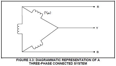
3.3.1 State the relationship between the values of the phase voltage and the line voltage in FIGURE 3.3. (1)
3.3.2 Draw a fully labelled phasor diagram that represents FIGURE 3.3. (3)
3.4 Explain why the generated electricity is lower at the point of distribution than at the point of generation. (2)
3.5 FIGURE 3.5 below is a diagrammatic representation of power-factor correction capacitors in a three-phase system. Answer the questions that follow.
3.5.1 Explain how the power-factor correction capacitor will affect the lagging current through the motor. (2)
3.5.2 State TWO advantages of power factor correction for the supplier. (3)
3.6 A three-phase star-connected alternator generates 250 kVA at a power factor of 0,9 lagging and has a line voltage of 380 V.
Calculate the:
3.6.1 Phase voltage (2)
3.6.2 Active power (3)
3.6.3 Reactive power (5)
3.7 State the function of a kWh meter. (2)
[30]
QUESTION 4: THREE-PHASE TRANSFORMERS
4.1 Name TWO cooling methods used in a dry transformer. (2)
4.2 State the main cause that contributes to heat generation in transformers. (1)
4.3 State TWO safety precautions when working with transformers. (2)
4.4 FIGURE 4.4 below is a diagrammatic representation of a three-phase transformer connection. Answer the questions that follow.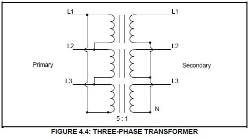
4.4.1 Identify the type of transformer connection in FIGURE 4.4. (1)
4.4.2 Name TWO applications of the transformer in FIGURE 4.4 (2)
4.4.3 State, with a reason, whether the transformer is a step-up or a step-down transformer. (2)
4.5 Compare single-phase transformers with three-phase transformers when they supply the same three-phase load. Refer to the following:
4.5.1 Economic cost (1)
4.5.2 Efficiency (1)
4.6 Refer to FIGURE 4.6 below and describe how the Buchholz relay would protect a transformer under minor and major faulty conditions.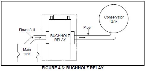
4.7 Refer to FIGURE 4.7 below and answer the questions that follow.
Given:
TR = 5 : 1
Vph1 = 2 000 V
S = 50 kVA
POUT = 45 kW
Transformer losses = 500 W
Calculate the:
4.7.1 Secondary phase voltage (3)
4.7.2 Efficiency of the transformer (3)
4.7.3 Power factor of the transformer (3)
4.7.4 Current drawn by the load (3)
[30]
QUESTION 5: THREE-PHASE MOTORS AND STARTERS
5.1 FIGURE 5.1 below shows the rotor of an induction motor. Answer the questions that follow.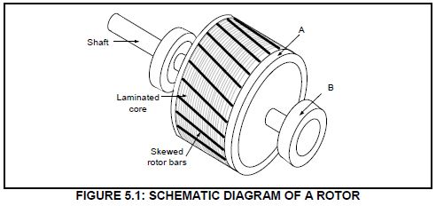
5.1.1 Name parts A and B. (2)
5.1.2 State ONE important advantage of using this type of a rotor compared to using a motor with brushes and slip rings.(1)
5.1.3 Give ONE reason why the rotor bars are skewed. (1)
5.2 Explain the following terms with reference to motors:
5.2.1 Slip (2)
5.2.2 Commissioning (2)
5.3 State ONE type of mechanical inspection that must be conducted after installation and before commissioning. (1)
5.4 A three-phase delta-connected motor has a total of 12 poles and is connected to a 380 V/50 Hz supply. The input power to the motor is 25 kW with a lagging power factor of 0,95. The total losses on the motor are 800 W.
Given:
f = 50 Hz
Pin = 25 kW
losses = 800 W
Cos θ = 0,95
poles = 12
Calculate the:
5.4.1 Pole pairs per phase (2)
5.4.2 Synchronous speed of the motor (3)
5.4.3 Rotor speed with a 3% slip (3)
5.4.4 Efficiency of the motor (3)
5.5 FIGURE 5.5 below shows the control circuit of a three-phase motor starter.
5.5.1 Identify the control circuit in FIGURE 5.5. (1)
5.5.2 Explain the function of the following components used in the circuit.
- OLN/C (2)
- MC2N/O (2)
5.5.3 Explain why the MC1N/C contact is connected in series with the MC2 contactor coil. (2)
5.6 The following information is given about a three-phase induction motor with reference to the setting of the overload:
Given:
VS = 380 V
I max = 100 A
Calculate the full-load current of the motor if the maximum starting-line current is seven times the full-load current. (3)
[30]
QUESTION 6: PROGRAMMABLE LOGIC CONTROLLERS (PLCs)
6.1 Draw a fully labelled diagram of a PLC scan cycle. (3)
6.2 State TWO advantages of a PLC system over a hardwired relay system. (2)
6.3 Explain why the PLC wiring and connections must be checked before switching on. (2)
6.4 Explain why a PLC system is safer than a hardwired system when a fault condition occurs. (2)
6.5 Describe the following with reference to PLCs:
6.5.1 Central processing unit (2)
6.5.2 Soft-wired systems (2)
6.5.3 PLC software (1)
6.6 Explain the difference between an analogue signal and a digital signal. (2)
6.7 State the correct use of the following PLC program functions:
6.7.1 Markers/Flags (1)
6.7.2 Contactor (1)
6.8 FIGURE 6.8 below shows the American and IEC symbols of a NAND gate.
Draw the ladder logic diagram of FIGURE 6.8.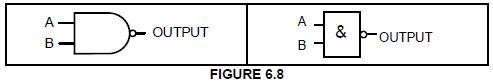
6.9 With reference to sensors:
6.9.1 Explain the term sensor. (2)
6.9.2 Name TWO types of sensors other than a proximity sensor. (2)
6.9.3 bState TWO uses of a proximity sensor. (2)
6.10 FIGURE 6.10 below shows the control circuit of a manual sequence starter.
Draw the PLC ladder logic program that will execute the same function.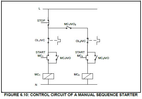
6.11 Name TWO timer functions used in PLC programming. (2)
6.12 Refer to FIGURE 6.12 below and explain the sequence of operation of the circuit.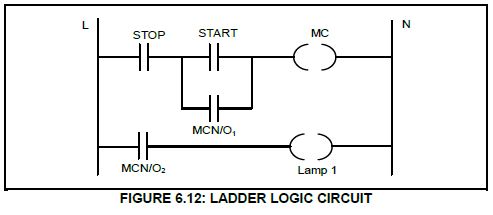
6.13 Name TWO components used in the output module of a PLC to drive a high current inductive load. (2)
6.14 Refer to FIGURE 6.14 below and answer the questions that follow.
6.14.1 Identify FIGURE 6.14. (1)
6.14.2 Explain the purpose of the braking resistor. (2)
6.15 Explain how regenerated energy can be used. (3)
6.16 FIGURE 6.16 below is a block diagram of a variable speed drive (VSD)
6.16.1 Label block A. (1)
6.16.2 State the main component used in the filter circuit. (1)
6.16.3 Describe the operation of the inverter. (5)
6.16.4 State TWO advantages of using VSDs over drive motors. (2)
[60]
TOTAL: 200