Civil Technology Civil Services Grade 12 Questions - NSC Exams Past Papers and Memos September 2019 Preparatory Examinations
Share via Whatsapp Join our WhatsApp Group Join our Telegram GroupREQUIREMENTS:
- ANSWER BOOK
- Drawing instruments
- A non-programmable pocket calculator
INSTRUCTIONS AND INFORMATION
- This question paper consists of SIX questions: TWO questions are generic and FOUR questions are subject specific.
- Answer ALL the questions.
- Answer each question as a whole. Do NOT separate subsections of questions.
- Start the answer to EACH question on a NEW page.
- Do NOT write in the margins of the ANSWER BOOK.
- You may use sketches to illustrate your answers.
- Write ALL calculations and answers in the ANSWER BOOK or on the attached ANSWER SHEETS.
- Use the mark allocation as a guide to the length of your answers.
- Make drawings and sketches in pencil, fully dimensioned and neatly finished off with descriptive titles and notes to conform to the SANS/SABS Code of Practice for Building Drawings.
- For the purpose of this question paper, the size of a brick should be taken as 220 mm x 110 mm x 75 mm
- Use your own discretion where dimensions and/or details have been omitted.
- Answer QUESTIONS 2.2, 3.7, 4.9 and 6.1 on the attached ANSWER SHEETS using drawing instruments where necessary.
- Write your NAME on every ANSWER SHEET and hand them in with your ANSWER BOOK, whether you have answered the question or not.
- Due to electronic transfer, drawings in the question paper are NOT to scale.
QUESTIONS
QUESTION 1: SAFETY, OHSA AND MATERIALS (GENERIC)
Start the question on a NEW page.
1.1 What is the maximum height of a trestle scaffold? (1)
1.2 Building rubble should never be dropped from elevated areas. Name the correct method of disposing rubble from elevated areas. (2)
1.3 Briefly motivate why a construction site must be suitably cordoned off. (2)
1.4 Choose the correct answer from those in brackets with regards to the construction process of stairs:
1.4.1 Stairways must be installed at least (30° / 25°) from the horizontal platform and not more than (45° / 50°) from a wall. (2)
1.4.2 Stairways that will not be a permanent part of the building construction must have landings of at least (760 x 560 mm / 750 x 600 mm) for every (3,7 m / 2,5 m) or less vertical rise. (2)
1.5 FIGURE 1.5 shows a ladder that is placed against a wall. What is the correct measurement at A to keep it stable? Show or indicate how to achieve the ratio. (2) 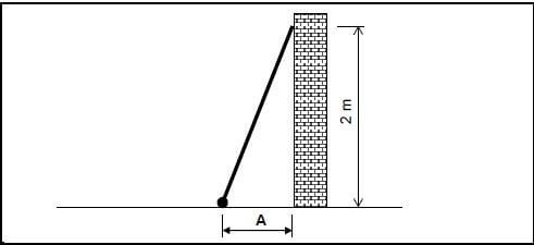
FIGURE 1.5
1.6 Explain the safety requirements when extending a ladder. (2)
1.7 Briefly explain the electroplating process of metals. (2)
1.8 Name THREE advantages of electroplating metals. (3 x 1) (3)
1.9 Name TWO advantages of galvanising metals. (2 x 1) (2) [20]
QUESTION 2: GRAPHICS, JOINING AND EQUIPMENT (GENERIC)
Start this question on a NEW page.
2.1 Indicate if the following statements, regarding site plans, are TRUE or FALSE. Write only ‘true’ or ‘false’ next to the question number in your ANSWER BOOK.
2.1.1 Scale 1 : 10 is used (1)
2.1.2 Ground contours are shown (1)
2.1.3 Layout of sewage is shown (1)
2.1.4 The proposed work is indicated in red (1)
2.1.5 Floor finishes of rooms are indicated (1)
2.2 FIGURE 2.2 on ANSWER SHEET A shows an incomplete floorplan of a flat to scale 1 : 100. Complete the floorplan by using the following information:
2.2.1 Outside door at 2.2.A (2)
2.2.2 Window at 2.2.B (2)
2.2.3 Water closet at 2.2.C (2)
2.2.4 Washbasin at 2.2.D (2)
2.2.5 Wash tub at 2.2.E (2)
2.2.6 One-way switch single pole at 2.2.F (2)
2.2.7 Fluorescent light at 2.2.G (2)
2.2.8 Socket outlet at 2.2.H (2)
2.2.9 Grease trap at 2.2.I (2)
2.2.10 Wall-mounted light at 2.2.J (2)
2.3 Identify the different types of bolts in FIGURES 2.3.1, 2.3.2 and 2.3.3. 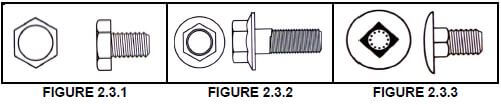 (3)
(3)
2.4 Answer the following questions on the tool in FIGURE 2.4. 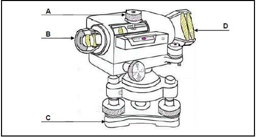
FIGURE 2.4
2.4.1 Identify the tool in FIGURE 2.4. (1)
2.4.2 Name ONE use of this tool. (1 x 1) (1)
2.4.3 Name the different parts A–D. (4 x 1) (4)
2.4.4 Name TWO uses of a laser level. (2)
2.5 Explain why the laser level should not be stored in extremely cold areas. Refer to the moisture inside the tool. (2)
2.6 Explain the meaning of the following code for Rawl bolts: M08/25. (2) [40]
TOTAL SECTION A: 60
QUESTION 3: SAFETY, MATERIAL AND CONSTRUCTION (SPECIFIC)
Start this question on a NEW page.
3.1 What is the purpose of an extractor fan when working in manholes? (1)
3.2 Briefly motivate why a person entering a manhole must wear a safety harness. (2)
3.3 Identify the safety harness appliances in FIGURES 3.3.1 to 3.3.3.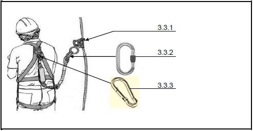 (3)
(3)
3.4 Fully motivate why zinc is seen as a highly reactive metal. (4)
3.5 What type of water causes chemical corrosion in copper? (1)
3.6 Complete the following descriptions of the factors that determine galvanic corrosion through thermodynamic and kinetic conditions:
- The difference between the 3.6.1 potential of the two metals. (1)
- Contact resistance at the 3.6.2 between the two metals. (1)
- Electrical resistance of the 3.6.3 solution. (1)
- The presence of a 3.6.4 film. (1)
3.7 FIGURE 3.7 on ANSWER SHEET B shows layer 1 of a double return angle in a one-brick wall in stretcher bond. Draw the alternate layer of the one-brick wall to scale 1 : 10 on ANSWER SHEET B. (10)
3.8 Name TWO positions in a drainage system where manholes must be placed. (2 x 1) (2)
3.9 Indicate whether the following statements are TRUE or FALSE. Write only ‘true’ or ‘false’ next to the number in the ANSWER BOOK.
3.9.1 The gradient for a Ø 100 mm drain pipe is 1 : 20. (1)
3.9.2 The temporary timber support structures that are placed to prevent excavations from caving in, are called shoring. (1)
3.9.3 The high-pressure jetting method to compact backfill material of drain trenches is only recommended for sandy soil. (1) [30]
QUESTION 4: COLD-WATER SUPPLY, HOT-WATER SUPPLY AND EQUIPMENT (SPECIFIC)
Start this question on a NEW page.
4.1 Briefly describe the working of a water meter which allows it to determine the amount of water used. (2)
4.2 Answer the following questions with regard to the tap in FIGURE 4.2. 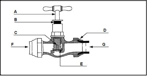
FIGURE 4.2
4.2.1 What is this type of tap called? (1)
4.2.2 Name the parts A–E. (5)
4.2.3 Which letter, F or G, indicates the flow direction of the water? (1)
4.2.4 Name TWO positions where this type of tap can be installed. (2 x 1) (2)
4.3 What is the purpose of the aerator which is installed at the end of a tap? (1)
4.4 What is the first step to be followed when water supply pipes are repaired? (1)
4.5 Briefly motivate why the water supply pipes which have to be repaired, should be free of sand particles before they are joined. (2)
4.6 Briefly motivate why the cold-water inlet is at the bottom and the hot-water outlet at the top of a high-pressure geyser. (2)
4.7 Choose a description with regard to a high-pressure geyser from COLUMN B that matches the correct item in COLUMN A. Write only the correct letter (A–G) next to the question number (4.7.1–4.7.5) in the ANSWER BOOK, for example, 4.7.6 H.
| COLUMN A | COLUMN B |
4.7.1 Drip tray |
|
(5)
4.8 Describe the following regulations which are applicable to geysers:
4.8.1 The position of the electric isolator switch (2)
4.8.2 The weight of the geyser when it is installed (2)
4.9 Complete the diagrammatic representation of a pumped direct solar hot-water system on ANSWER SHEET B, by drawing in the following parts:
4.9.1 Draw the pressure-relief valve, non-return valve and pressure-reducing valve symbols in the correct openings marked 4.9 in the pipe system. (6)
4.9.2 Draw the hot-water pipe system from the solar panels to the storage tank. (5)
4.10 Name THREE maintenance measures which are applicable to the pipe-thread cutting machine. (3 x 1) (3) [40]
QUESTION 5: DRAINAGE, SANITARY FITMENTS AND QUANTITIES (SPECIFIC)
Start this question on a NEW page.
5.1 Define the following terms:
5.1.1 Soil water (2)
5.1.2 Waste water (2)
5.2 Briefly motivate why sufficient volumes of water must be discharged into a drain system. (2)
5.3 Answer the following questions with regard to the drain pipe joint in FIGURE 5.3. 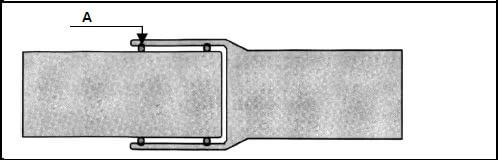
FIGURE 5.3
5.3.1 What is this type of joint called? (1)
5.3.2 What is part A called? (1)
5.3.3 What is the purpose of A? (1)
5.4 Fully describe the cause of a siphonic action in a drain system. (6)
5.5 Indicate whether the following statements are TRUE or FALSE. Write only ‘true’ or ‘false’ next to the number in the ANSWER BOOK.
5.5.1 An inspection chamber is not deeper than 750 mm. (1)
5.5.2 A manhole must not be installed further than 2 m from the boundary wall. (1)
5.5.3 A manhole ramp keeps the water lock in a drain system. (1)
5.5.4 A vacuum tank must be pumped out regularly. (1)
5.6 Briefly describe the method to remove a blockage in a sink soil-water pipe with a plunger. (3)
5.7 Name TWO properties of ceramic for the use of sanitary fitments. (2 x 1) (2)
5.8 Answer the following questions with regard to the sink installation in FIGURE 5.8. 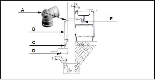
FIGURE 5.8
5.8.1 Identify the parts A–E. (5)
5.8.2 What is the purpose of part A? (1)
5.8.3 What is the sectional size of part B? (1)
5.9 FIGURE 5.9 shows the drain lay-out, to scale 1 : 100, of a building with a length of 6 000 mm and width of 3 000 mm. Determine the following quantities for the drain system. 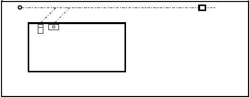
FIGURE 5.9
5.9.1 The number of fixed sanitary fitments needed (1)
5.9.2 The total length of branch pipes needed (2)
5.9.3 The total length of sewer pipes needed (1)
5.9.4 The number of access openings which must be installed (1)
5.10 A cylindrical water supply tank is 2 800 mm high and has a diameter of 1 800 mm. Determine the following: (Show all calculations and formulae)
5.10.1 The volume of the tank in m³ (3)
5.10.2 The volume of water that the tank can hold (1) [40]
QUESTION 6: GRAPHICS AS A MEANS OF COMMUNICATION, ROOFWORK, STORM WATER AND JOINING (SPECIFIC)
Start this question on a NEW page.
6.1 FIGURE 6.1 on ANSWER SHEET C shows the top and front elevations of a cylindrical pipe with a 45° cut-off. Draw the development of the pipe on ANSWER SHEET C. Show all construction lines. (21)
6.2 What is the maximum spacing of the gutter brackets for galvanised mild steel gutters? (1)
6.3 Briefly describe the purpose of flashings in roof construction. (2)
6.4 What is the purpose of the concrete shoe underneath the gutter downpipe? (1)
6.5 Indicate whether the following statements are TRUE or FALSE. Write only ‘true’ or ‘false’ next to the number in the ANSWER BOOK.
6.5.1 The municipality is responsible for all public stormwater systems. (1)
6.5.2 Stormwater must be directed into sewage systems. (1)
6.5.3 Chemicals may not be directed into stormwater systems. (1)
6.6 Name TWO properties of resin flux for soldering work. (2 x 1) (2) [30]
TOTAL: 200
ANSWER SHEET A | CIVIL TECHNOLOGY GENERIC | NAME: |
2.2 Use the information on ANSWER SHEET A and complete the floorplan to scale 1 : 100. 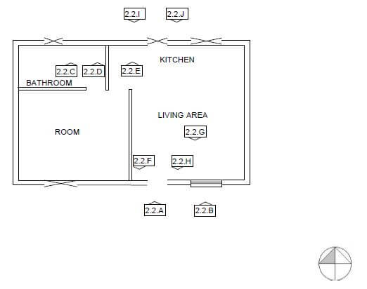
Outside door at 2.2.A | 2 | |
Window at 2.2.B | 2 | |
Water closet at 2.2.C | 2 | |
Washbasin at 2.2.D | 2 | |
Sink unit at 2.2.E | 2 | |
One-way switch-single pole 2.2.F | 2 | |
Fluorescent light at 2.2.G | 2 | |
Socket outlet at 2.2.H | 2 | |
Grease trap at 2.2.I | 2 | |
Wall-mounted light at 2.2.J | 2 | |
TOTAL: | 20 |
ANSWER SHEET B | CIVIL TECHNOLOGY CIVIL SERVICES | NAME: |
3.7 FIGURE 3.7 on ANSWER SHEET B shows layer 1 of a double return angle in a one-brick wall in stretcher bond. Draw the alternate layer of the one brick wall to scale 1 : 10 on ANSWER SHEET B. (10) 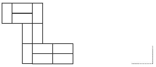
Brickwork | 8 | |
Application of scale | 2 | |
TOTAL: | 10 |
4.9 Complete the diagrammatic representation of a pumped direct solar hot-water system on ANSWER SHEET B, by drawing in the following parts: 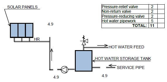
Pressure-relief valve | 2 | |
Non-return valve | 2 | |
Pressure-reducing valve | 2 | |
Hot water pipework | 5 | |
TOTAL: | 11 |
ANSWER SHEET C | CIVIL TECHNOLOGY CIVIL SERVICES | NAME: |
6.1 FIGURE 6.1 on ANSWER SHEET C shows the top and front elevations of a cylindrical pipe with a 45° cut-off.
Draw the development of the pipe on ANSWER SHEET C. Show all construction lines. (21) . 
Base line A-B | 1 | |
Seam lines A-C and B-D | 1 | |
Dividing lines 0-12 on top view | 6 | |
Vertical and horizontal construction lines A1-A7 | 7 | |
Intersection points and development lines B1-B11 | 6 | |
TOTAL: | 21 |