MECHANICAL TECHNOLOGY(WELDING) GRADE 12 MEMORANDUM - NSC PAST PAPERS AND MEMOS NOVEMBER 2019
Share via Whatsapp Join our WhatsApp Group Join our Telegram GroupMECHANICAL TECHNOLOGY: WELDING AND METALWORK
GRADE 12
NATIONAL SENIOR CERTIFICATE
NOVEMBER 2019
MEMORANDUM
QUESTION 1: MULTIPLE-CHOICE (Generic)
1.1 B ✓(1)
1.2 C ✓ (1)
1.3 A ✓ (1)
1.4 C ✓ (1)
1.5 A ✓ (1)
1.6 C ✓ (1)
[6]
QUESTION 2: SAFETY (Generic)
2.1 Machine safety rule:
- Know how to switch the machine off / emergency stop.✓
- Wear personal protective equipment (PPE). ✓
- Know how to use the machine.✓
- Ensure that all guards are in place. ✓
- No tools lying on the machine. ✓
- Work piece is properly secured. ✓
- Check the condition of the machine. ✓
- Follow manufacture's specifications before operating a machine. ✓
- Operator must have authorization to working on a machine. ✓
- Make sure the machine is not locked out. ✓
- Ensure that the machine setup is correct and safe. ✓
- Ensure that the machine area is clean and safe. ✓
(Any 1 x 1) (1)
2.2 Drill press safety precautions:
- To prevent injuries. ✓
- To improve accuracy. ✓
- To prevent work piece rotating/moving. ✓
- To prevent the drill bit from breaking. ✓
(Any 1 x 1) (1)
2.3 Hydraulic press safety rules:
- Make sure the press is in a good working condition. ✓
- Take notice of the pre-determined maximum pressure of the hydraulic press. ✓
- Make sure the area around the press is clean and free of oil, grease and water. ✓
- Ensure that the platform is rigid and square to the cylinder. ✓
- Ensure that suitable jigs and prescribed equipment is available. ✓
- Check hydraulic pipes for leaks or cracks. ✓
- Check supporting pins are not worn out and fitted properly. ✓
- Check fluid levels. ✓
- Compressive force must be applied at 90° to the object.✓
- Check cable and pulleys on the platform if equipped. ✓
- Correct PPE. ✓
- Pressure gauge must be checked and calibrated. ✓
- Ensure that all guards are in place. ✓
(Any 2 x 1) (2)
2.4 Reasons for wearing surgical gloves:
- To prevent HIV/AIDS or any blood related infections being transmitted✓
- To prevent contamination of the open wounds✓ (2)
2.5 Safe handling of portable electrical equipment:
- Ensure the electrical cord and plug, are in a good condition. ✓
- Ensure all safety guards are in place. ✓
- Ensure that the correct attachments (drill bits, blades etc.) are fixed in the correct way. ✓
- Do not force the machine/equipment.✓
- Operate according to manufacturer instructions. ✓
- Avoid contact with water.✓
- Keep the cable away from heat, oil, sharp edges and moving parts. ✓
- Make sure that the wires don't wrap around each other. ✓
- Avoid dropping the machine. ✓
- Check the condition of the equipment. ✓
(Any 2 x 1) (2)
2.6 Responsibility of employer:
- Provide and maintain working systems, work area, equipment and tools in a safe condition. ✓
- Eliminate or reduce any potential hazard. ✓
- Produce, handle, store and transport goods safely.✓
- Ensure that every person employed complies with the requirements of this OHS Act. ✓
- Enforce measures if necessary in the interest of health and safety. ✓
- Appoint a person who is trained and who have the authority to ensure that the employee takes precautionary measures. ✓
- Inform employees of the hazards to his health and safety attached to any duty or work situation. ✓
- Provide first aid equipment. ✓
(Any 1 x 1) (1)
2.7 Responsibility of employee:
- Pay attention to their own and other people's health and safety. ✓
- Co-operate with the employer regarding the OHS Act. ✓
- Carry out a lawful order given to them. ✓
- Report any situation that is unsafe or unhealthy.✓
- Report all incidents and accidents. ✓
- Not to interfere with any safety equipment or misuse such equipment.✓
- Obey all safety rules. ✓
(Any 1 x 1) (1)
[10]
QUESTION 3: MATERIAL (Generic)
3.1 Filing test:
- Use the right ✓ filing skills. ✓
- File on the tip or edge ✓✓ of the metal.
- By applying chalk ✓ to the file surface. ✓
(Any 1 x 2) (2)
3.2 Purpose of heat treatment of steel:
Heat treatment of steel is done to change ✓ the properties/grain structure ✓ of steel. (2)
3.3 Reasons for tempering hardened steel:
- To reduce ✓ the brittleness ✓ caused by the hardening process.
- To relieve ✓ strain ✓ caused during hardening process.
- To increase ✓ the toughness ✓ of the steel.
- To give hardened work piece a more ✓ fine-grained structure. ✓
(Any 2 x 2) (4)
3.4 Heat treatment processes on steel:
3.4.1 Annealing:
- The steel is heated to the prescribed temperature. ✓
- The steel is soaked at that temperature for the required time. ✓
- The steel is then cooled very slowly to produce maximum softness.✓ (3)
3.4.2 Hardening:
- The steel is heated slightly higher than the upper critical temperature. (AC3) ✓
- The steel is soaked at that temperature for the required time. ✓
- The steel is then rapidly cooled by quenching in rapid cooling medium. ✓(3)
[14]
QUESTION 4: MULTIPLE-CHOICE QUESTIONS (Specific)
4.1 D ✓ (1)
4.2 A ✓ (1)
4.3 C ✓ (1)
4.4 D ✓ (1)
4.5 B ✓ (1)
4.6 D ✓ (1)
4.7 D ✓ (1)
4.8 C✓ (1)
4.9 A ✓ (1)
4.10 C ✓ (1)
4.11 A ✓ (1)
4.12 C ✓ (1)
4.13 B ✓ (1)
4.14 D ✓ (1)
[14]
QUESTION 5: TERMINOLOGY (TEMPLATES) (Specific)
5.1 Abbreviation:
OSU Other ✓ Side Up ✓ (2)
5.2 Plate girder:
Is a combination of plates and angle iron ✓ welded together. ✓(2)
5.3 Purpose of supplementary welding symbols:
To indicate the additional/supplementary information regarding the weld. ✓ (1)
5.4 Fusion welds:
- Spot welding ✓
- Projection ✓
- Seam welding ✓
- Foil seam welding ✓
- Flash or resistance butt ✓
- Gas welding ✓
- MIG/MAGS Welding ✓
- Arc welding ✓
(Any 4 x 1) (4)
5.5 Supplementary weld symbols:
5.5.1 Grind ✓ (1)
5.5.2 Flame ✓ (1)
5.5.3 Machine ✓ (1)
5.5.4 Flush ✓ (1)
5.5.5 Convex ✓ (1)
5.6 Material calculations:
Mean diameter = Outside diameter - plate thickness
=300 - 20
= 280 mm
Mean circumference = π x mean diameter
= π x 280
= 879.65 mm, (7)
5.7 Weld dimensions:
- 30°: the included angle in degree ✓
- 5: root gap or root opening in mm ✓ (2)
[23]
QUESTION 6: TOOLS AND EQUIPMENT (Specific)
6.1.1 Power saw/Reciprocating saw:
- The blade is tensioned in the frame ✓ and cuts in a forward stroke and the blade is lifted in the backward (reciprocating) motion. ✓
- The blade assembly is raised and lowered ✓ by hydraulic controls to ensure that the cutting pressure is optimum. ✓ (4)
6.1.2 Manual guillotine:
- This guillotine is operated by a foot/hand pedal/lever that activates a pressure plate/blade guard. ✓
- The blade cuts the material. ✓
- The cut material is ejected at the back of the machine. ✓
- Extension bars lengthen the work surface and support longer pieces of material. ✓(4)
6.1.3 Horizontal pyramid rolls:
- Electrical/Power or hand driven. ✓
- The rollers are arranged so that, when viewed from the side, they give the impression of a pyramid. ✓
- All rollers are mounted in a horizontal position, with the bottom two fixed and rotating in unison. ✓
- The top roller is adjustable (up or down); applying downward pressure on the metal plate being rolled that will cause it to deflect and form the round shape. ✓ (4)
6.2 Bench Grinder:
- To sharpen cutting tools and drill bits. ✓
- To removing rough edges. ✓
- To removing excess material. ✓ (3)
6.3 Materials that can be cut with a plasma cutter:
- Mild steel ✓
- Alloy steels ✓
- Stainless steels ✓
- Non-ferrous metals ✓
(Any 3 x 1) (3)
[18]
QUESTION 7: FORCES (Specific)
7.1 Frame works: (12)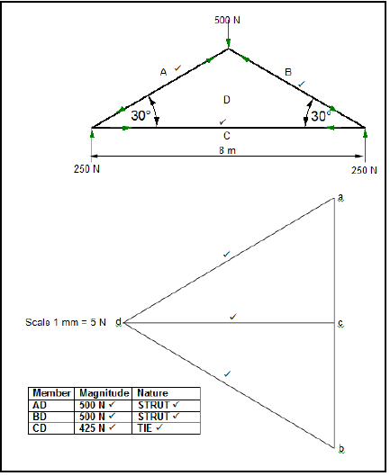
7.2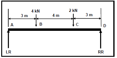
7.2.1 Reactions at supports RL and RR:
Take moments about RR:
LR x 10 = (4 x 7)+(2 x 3)
LR = 3,4 kN
Take moments about LR:
RR x 10 =(2 x 7)+(4 x 3)
RR = 2,6 kN (6)
7.2.2 Bending moments:
BMA = 0 3,4 0 kN.m A
BMB = (3 x 3,4) - (0 x 4) 10,2 kN.m B
BMC = (7 x 3,4) - (4 x 4) - (0 x 2) 7,8 kN.m C
BMD = (10 x 3,4) - (7 x 4) - (3 x 2) + (0 x 2,6) 0 kN.m D (4)
7.2.3 Shear forces:
SFA = 0kN A OR UFA = 3,4kN
SFB = 3,4- 4 -0,6 kN
SFC = 3,4 - (4 + 2) -2,6 kN
SFD = 0kN OR UFD 2,6kN (4)
7.2.4 SF and BM diagrams: (6)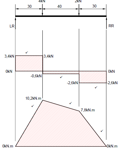
7.3 Stress and Strain:
7.3.1 Stress:
A = πd 2
4
= π x 0,012
4
A = 7,85 x 10⁻⁵ m2
Stress = Load
Area
= 50 x 10 3
7,85 x 10-5
= 636942675,2 Pa
= 636,94MPa(5)
7.3.2 Strain:
Strain = ΔL
OL
= 0,6 x 10⁻³
20
= 3 x 10⁻⁵ (3)
7.3.3 Final length:
Final length = OL + ΔL
= 20 + 0,6 + 10-3
= 20,0006m (2)
7.3.4 Young’s modulus:
E = Stress
Strain
E = 636,94 x 10⁶
3 x 10⁻⁵
E = 2,1231 x 10¹³ Pa
E 21231,33 GPa
QUESTION 8: JOINING METHODS (Inspection of weld) (Specific)
8.1 Causes of arc-welding defects:
8.1.1 Undercutting:
- To high welding current ✓
- Electrode at incorrect angle ✓
- Excessive weaving ✓
- Arc length too long ✓
- Travel speed to high ✓
(Any 2 x 1) (2)
8.1.2 Causes of slag inclusion:
- Defective consumables. ✓
- Inadequate shielding gas. ✓
- Joint contamination. ✓
- Too low current. ✓
- Improper slag removal from previous weld. ✓
- Excessive weaving ✓
- Electrode at incorrect angle ✓
(Any 2 x 1) (2)
8.2 Factors determining gas pressure for oxy acetylene welding:
- The nozzle size.✓
- Thickness of material. ✓ (2)
8.3 Factors determining current setting for welding:
- Base metal type.✓
- Base metal thickness. ✓
- Electrode diameter. ✓
- Position of the weld. ✓
(Any 2 x 1)(2)
8.4 Preventative measures for weld defects:
8.4.1 Porosity:
- Cleaning the welding surface. ✓
- Use dry electrodes. ✓
- Avoid rust on electrode. ✓
- Ensure that supply of shielding gas is not interrupted. ✓
- Avoid welding in windy conditions. ✓
- Use correct arc length. ✓
(Any 2 x 1) (2)
8.4.2 Incomplete penetration:
- Set to correct current setting. ✓
- Apply the correct electrode angle. ✓
- Increase the travel speed.✓
- Use the correct root gap. ✓
- Ensure the correct joint preparation.✓
(Any 2 x 1) (2)
8.5 Guided bend test:
- Lack of fusion.✓
- Incomplete penetration. ✓
- Cracks in the weld metal.✓
- Quality of the weld at the face and root of the weld. ✓
(Any 2 x 1) (2)
8.6 Visual inspection process:
- Shape of profile. ✓
- Uniformity of the surface. ✓
- Overlap. ✓
- Undercutting. ✓
- Penetration bead. ✓
- Root groove. ✓
- Slag inclusion. ✓
- Spatter. ✓
- Cracks. ✓
(Any 3 x 1) (3)
8.7 X-ray test:
- The X-ray or gamma ray source is placed in front of the object being tested. ✓
- The film is put behind the object being tested. ✓
- The source is activated and the X-rays/gamma penetrate the test piece. ✓
- As they pass through the areas of lower density (air pockets, cracks or inclusions) ✓the rays expose the film as lighter on the negative, indicating a welding defect.✓
- Film or picture need to be analyzed. ✓ (6)
[23]
QUESTION 9: JOINING METHODS (Stresses and Distortion) (Specific)
9.1 Distortion:
Weld distortion is the warping of the base plate ✓ caused by heat from the welding arc/flame. ✓ (2)
9.2 Effect of cold working on steel:
- To break down the crystal structure elongating the grains. ✓
- It gives the metal greater hardness and tensile strength. ✓
- It reduces ductility. ✓
- Steel can be made to recrystallize under the action of heat. ✓ (4)
9.3 Factors that affect distortion and residual stress:
- If the expansion that occurs when metal is heated is resisted ✓then deformation will occur. ✓
- When contraction that occurs on cooling is resisted ✓ then a stress will be applied. ✓
- If this stress causes movement ✓then distortion occurs.✓
- If this stress does not cause movement ✓ then there will be residual stress in the welded joint. ✓
(Any 2 x 2) (4)
9.4 Rate of cooling:
- The size of the work piece. ✓
- Weld thickness. ✓
- Thermal conductive properties of parent metal. (Type of material) ✓ (3)
9.5 The iron-carbon equilibrium diagram:
- Ferrite and pearlite ✓
- Ferrite and austenite ✓
- Austenite ✓
- Cementite and austenite ✓
- Pearlite and cementite ✓ (5)
[18]
QUESTION 10: MAINTENANCE (Specific)
10.1 Lockout on machines:
To ensure that nobody can turn on the machine✓ while maintenance is being carried out.✓ (2)
10.2 Tagging plates:
It has multiple holes, so that more than one technician can lock out the machine simultaneously. ✓ (1)
10.3 Aspects of plant and equipment maintenance:
- Do not ignore maintenance. ✓
- Do not ignore reports of damaged or unsafe equipment. ✓
- Do not ignore faulty or damaged equipment. ✓
- Do not ignore inspection. ✓
(Any 2 x 1) (2)
10.4 Maintenance guidelines of the horizontal band saw:
- Check electrical wiring and isolation. ✓
- Change the band saw blade as required. ✓
- Check band wheels at every blade change. ✓
- Monitor band wheel bearings.✓
- Inspect band guides. ✓
- Inspect the condition of the guards. ✓
- Check blade tension and alignment. ✓
- Inspect the hydraulic system and oil level.✓
- Check vice for wear on both stationary and movable parts. ✓
- Align vice with the blade. ✓
- Inspect the chip removal system daily. ✓
(Any 2 x 1) (2)
10.5 Effect of overloading of the rolling machine:
It limits the lifespan ✓ of bearings, gearbox and motor components. ✓(2)
[09]
QUESTION 11: DEVELOPMENT (Specific)
11.1 Square to rectangular hopper off centre: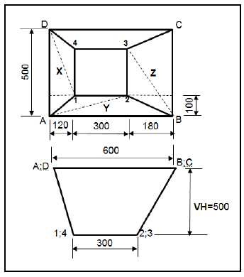
11.1.1 True lengths of A-1:
Vertical height = 500 mm
True length (A-1):
A - 1 = √1202 + 1002 + 5002
= √14400 + 10000 + 250000
= 523,83mm (4)
11.1.2 True length (A-2):
Vertical height = 500 mm
A - 2 = √1002 + 4202 + 5002
= √10000 + 176400 + 250000
= 660,61mm (4)
11.1.3 True length (B-2):
Vertical height = 500 mm
B - 2 = √1002 + 1802 + 5002
= √10000 + 32400 + 250000
= 540,74mm (4)
11.1.4 True length (B-3):
Vertical height = 500 mm
B - 3 = √1802 + 4002 + 5002
= √32400 + 160000 + 250000
= 665,13mm (4)
11.1.5 True length(D-1):
Vertical height = 500 mm
D - 1= √1202 4002 5002
= √14400 + 160000 + 250000
= 651,46mm (4)
[20]
TOTAL : [200]