MECHANICAL TECHNOLOGY(AUTOMOTIVE) GRADE 12 MEMORANDUM - NSC PAST PAPERS AND MEMOS NOVEMBER 2019
Share via Whatsapp Join our WhatsApp Group Join our Telegram GroupMECHANICAL TECHNOLOGY: AUTOMOTIVE
GRADE 12
NATIONAL SENIOR CERTIFICATE
NOVEMBER 2019
MEMORANDUM
QUESTION 1: MULTIPLE-CHOICE (Generic)
1.1 B ✓(1)
1.2 C ✓ (1)
1.3 A ✓ (1)
1.4 C ✓ (1)
1.5 A ✓ (1)
1.6 C ✓ (1)
[6]
QUESTION 2: SAFETY (Generic)
2.1 Machine safety rule:
- Know how to switch the machine off / emergency stop.✓
- Wear personal protective equipment (PPE). ✓
- Know how to use the machine.✓
- Ensure that all guards are in place. ✓
- No tools lying on the machine. ✓
- Work piece is properly secured. ✓
- Check the condition of the machine. ✓
- Follow manufacture's specifications before operating a machine. ✓
- Operator must have authorization to working on a machine. ✓
- Make sure the machine is not locked out. ✓
- Ensure that the machine setup is correct and safe. ✓
- Ensure that the machine area is clean and safe. ✓
(Any 1 x 1) (1)
2.2 Drill press safety precautions:
- To prevent injuries. ✓
- To improve accuracy. ✓
- To prevent work piece rotating/moving. ✓
- To prevent the drill bit from breaking. ✓
(Any 1 x 1) (1)
2.3 Hydraulic press safety rules:
- Make sure the press is in a good working condition. ✓
- Take notice of the pre-determined maximum pressure of the hydraulic press. ✓
- Make sure the area around the press is clean and free of oil, grease and water. ✓
- Ensure that the platform is rigid and square to the cylinder. ✓
- Ensure that suitable jigs and prescribed equipment is available. ✓
- Check hydraulic pipes for leaks or cracks. ✓
- Check supporting pins are not worn out and fitted properly. ✓
- Check fluid levels. ✓
- Compressive force must be applied at 90° to the object.✓
- Check cable and pulleys on the platform if equipped. ✓
- Correct PPE. ✓
- Pressure gauge must be checked and calibrated. ✓
- Ensure that all guards are in place. ✓
(Any 2 x 1) (2)
2.4 Reasons for wearing surgical gloves:
- To prevent HIV/AIDS or any blood related infections being transmitted✓
- To prevent contamination of the open wounds✓ (2)
2.5 Safe handling of portable electrical equipment:
- Ensure the electrical cord and plug, are in a good condition. ✓
- Ensure all safety guards are in place. ✓
- Ensure that the correct attachments (drill bits, blades etc.) are fixed in the correct way. ✓
- Do not force the machine/equipment.✓
- Operate according to manufacturer instructions. ✓
- Avoid contact with water.✓
- Keep the cable away from heat, oil, sharp edges and moving parts. ✓
- Make sure that the wires don't wrap around each other. ✓
- Avoid dropping the machine. ✓
- Check the condition of the equipment. ✓
(Any 2 x 1) (2)
2.6 Responsibility of employer:
- Provide and maintain working systems, work area, equipment and tools in a safe condition. ✓
- Eliminate or reduce any potential hazard. ✓
- Produce, handle, store and transport goods safely.✓
- Ensure that every person employed complies with the requirements of this OHS Act. ✓
- Enforce measures if necessary in the interest of health and safety. ✓
- Appoint a person who is trained and who have the authority to ensure that the employee takes precautionary measures. ✓
- Inform employees of the hazards to his health and safety attached to any duty or work situation. ✓
- Provide first aid equipment. ✓
(Any 1 x 1) (1)
2.7 Responsibility of employee:
- Pay attention to their own and other people's health and safety. ✓
- Co-operate with the employer regarding the OHS Act. ✓
- Carry out a lawful order given to them. ✓
- Report any situation that is unsafe or unhealthy.✓
- Report all incidents and accidents. ✓
- Not to interfere with any safety equipment or misuse such equipment.✓
- Obey all safety rules. ✓
(Any 1 x 1) (1)
[10]
QUESTION 3: MATERIAL (Generic)
3.1 Filing test:
- Use the right ✓ filing skills. ✓
- File on the tip or edge ✓✓ of the metal.
- By applying chalk ✓ to the file surface. ✓
(Any 1 x 2) (2)
3.2 Purpose of heat treatment of steel:
Heat treatment of steel is done to change ✓ the properties/grain structure ✓ of steel. (2)
3.3 Reasons for tempering hardened steel:
- To reduce ✓ the brittleness ✓ caused by the hardening process.
- To relieve ✓ strain ✓ caused during hardening process.
- To increase ✓ the toughness ✓ of the steel.
- To give hardened work piece a more ✓ fine-grained structure. ✓
(Any 2 x 2) (4)
3.4 Heat treatment processes on steel:
3.4.1 Annealing:
- The steel is heated to the prescribed temperature. ✓
- The steel is soaked at that temperature for the required time. ✓
- The steel is then cooled very slowly to produce maximum softness.✓ (3)
3.4.2 Hardening:
- The steel is heated slightly higher than the upper critical temperature. (AC3) ✓
- The steel is soaked at that temperature for the required time. ✓
- The steel is then rapidly cooled by quenching in rapid cooling medium. ✓(3)
[14]
QUESTION 4: MULTIPLE-CHOICE QUESTIONS (Specific)
4.1 A ✓ (1)
4.2 C ✓ (1)
4.3 D ✓ (1)
4.4 B ✓ (1)
4.5 C ✓ (1)
4.6 D ✓ (1)
4.7 A ✓ (1)
4.8 B ✓ (1)
4.9 C ✓ (1)
4.10 B ✓ (1)
4.11 C✓ (1)
4.12 D & B ✓ (1)
4.13 B ✓ (1)
4.14 B ✓ (1)
[14]
QUESTION 5: TOOLS AND EQUIPMENT (Specific)
5.1 Cylinder leakage tester:
5.1.1
Labels:
- – Pressure control valve/Knob/Regulator ✓
- – Gauge/Meter✓
- – Compressor hose/Air hose/Pipe ✓
- – Spark plug connector/adapter/Hose/Pipe ✓ (4)
5.1.2 Purpose of cylinder leakage tester:
- To determine the percentage ✓ of gas leakage from a cylinder. ✓
- To determine the location ✓ of gas leaks from a cylinder. ✓
(Any 1 x 2) (2)
5.1.3 Procedure for cylinder leakage test:
- Turn the crank shaft until both valves on cylinder no. 1 are closed (piston no.1 is on power stroke). ✓
- Remove the spark plug and connect the spark plug adaptor (tester) to the spark plug hole. ✓
- Use a spanner to lock the crankshaft pulley so that it cannot turn. ✓
- Release air into the cylinder according to the prescribed pressure. ✓
- The reading will indicate the percentage gas leakage. ✓
- A hissing sound at various points indicates the location of the leak. ✓ (6)
5.2 Compression tester:
5.2.1 Purpose of compression test:
- To determine the amount of compression pressure ✓ from a specific cylinder during compression stroke (BDC – TDC). ✓
- To determine the condition ✓ of the engine's valves, valve seats and piston rings. ✓
(Any 1 x 2) (2)
5.2.2 Compression tester release valve:
- Remove the pressure from the gauge ✓ to ensure an accurate reading. ✓
- Remove the pressure from the gauge ✓ to prevent damage to the gauge. ✓
(Any 1 x 2) (2)
5.3 Gases analysed:
- Carbon monoxide (CO) ✓
- Hydrocarbon (HC) ✓
- Carbon dioxide (CO2) ✓
- Nitrogen oxide (NOx) ✓
- Sulphur dioxide(SO2) ✓
- Oxygen (O2) ✓
(Any 2 x 1) (2)
5.4 Purpose of turn tables:
Turn table makes it possible to turn ✓ the front wheels when conducting wheel alignment settings. ✓ (2)
5.5 Outcomes of dynamic wheel balancing is to check:
- The plane of imbalance. ✓
- The extent of unbalancing forces. ✓
- The direction of these forces. (clockwise or counter-clockwise)✓
- Wheels balanced on all planes. ✓
- Less vibration on the steering.✓
- Even tyre wear. ✓
(Any 3 x 1) (3)
[23]
QUESTION 6: ENGINES (Specific)
6.1 Crankshaft vibration:
- The action upon the shaft of unbalanced forces. ✓
- The torsional or twisting effect of the power strokes upon the shaft. ✓
- Worn vibration damper. ✓
- Uneven flywheel wear. ✓
- Unbalanced crankshaft. ✓
(Any 2 x 1) (2)
6.2 Vibration Damper:
6.2.1 Vibration damper ✓ (1)
6.2.2 Labels:
- – Crankshaft ✓
- – Crankshaft flange/pulley ✓
- – Secondary flywheel ✓
- – Friction disc/Rubber✓
- – Friction spring ✓
- – Spring plate/Disc ✓ (6)
6.2.3 The vibration damper adds mass to the crankshaft on the opposite side ✓ of the normal flywheel in order to counteract the torsion of the crankshaft. ✓ (2)
6.3 Firing order of an engine:
- The position of the cranks on the crankshaft. ✓
- The arrangement of the cams on the camshaft. ✓ (2)
6.4 'V8' angle:
90°✓ (1)
6.5 Intercooler:
To cool the air that has been compressed by the turbo-charger. ✓ (1)
6.6 Purpose of a supercharger:
- To fill the cylinder with an increased air pressure ✓✓that is higher than atmospheric pressure. ✓
- To increase ✓✓the compression pressure ✓✓in the cylinder.
- To increase ✓✓the volumetric efficiency ✓✓of the engine.
- To improve ✓ the performance. ✓✓
(Any 1 x 2) (2)
6.7 Centrifugal supercharger:
6.7.1 Centrifugal supercharger/blower ✓ (1)
6.7.2 Labels:
- – Air inlet ✓
- – Air outlet/Exhaust ✓
- – Casing/Housing/Cover/Body ✓
- – Impeller/Turbine ✓
- – Fins/Vanes/Blades ✓ (5)
6.7.3 Operation:
- This blower can be driven mechanically by means of a belt drive from the crankshaft. ✓
- The shaped fins on the impeller move the air around to the outer edge of the impeller into the housing.✓
- The rotating fins leave a low pressure behind it. ✓
- Due to atmospheric pressure, air rushes in to fill the low pressure at the centre of the impeller. ✓
- The impeller rotates so fast that a continuous movement of air is present, which now builds up a pressure as it is thrown at the rim or the edge. ✓ (5)
[28]
QUESTION 7: FORCES (Specific)
7.1 Swept volume:
Volume when the piston moves✓ from bottom dead centre to top dead centre.✓✓ (2)
7.2 Method to increase compression ratio:
- Remove shims between the cylinder block and cylinder head. ✓
- Fit thinner cylinder head gasket. ✓
- Machine metal from cylinder head. ✓
- Fit a piston with a higher crown. ✓
- Fit a crankshaft with a longer stroke/through. ✓
- Increase the bore of the cylinders/bigger pistons. ✓
(Any 3 x 1) (3)
7.3 Compression ratio:
7.3.1 Swept volume: πD2 x L
4
= π(9,0) 2 10,0
4
= 636,17 cm3 (3)
7.3.2 Original clearance volume:
Compression Ratio = SV + CV
CV
CV = SV
CR - 1
= 636,17
10,5 - 1
= 636,17
9,5
= 66,97 cm3 (3)
7.3.3 New bore diameter:
New compression ratio = SV+ 1
CV
11:1 = SV + 1
66,97
SV = 66,97 x 10
πD2 x L = 669,7
4
D2 = 669,7 x 4
π x 10
D = √85,27
= 9,23cm
= 92,34 mm (6)
7.4 Power:
7.4.1 Indicated Power:
IP = P x L x A x N x n
P = 1300 kPa
L = 160
1000
= 0.16m
A = πD2
4
= π0,122
4
= 1,13 x 10⁻² m
n = 4500
60 x 2
= 37,5 ps/s
n = 4 cylinders
IP = P x L x A x N x n
= (1300 x 103) x 0,16 x (1,13 x 10-2) x 37,5 x 4
= 352560
= 352,56 kW
7.4.2 Brake Power:
BP = 2π x N x T
= 2π 610 x 4500
60
= 2 π 610 75
= 287455,73 W
= 287,46 kW (4)
7.4.3 Mechanical efficiency:
= BP 100%
IP
= 287,46 x 100%
352,56
= 81,54% (2)
7.5 Mechanically efficiency is based on the relationship of the power developed within the engine ✓ and the actual brake power delivered at the fly wheel. ✓ (2)
7.6 Brake Power is the useable power ✓developed at the flywheel. ✓ (2)
[32]
QUESTION 8: MAINTENANCE (Specific)
8.1 Radiator cap pressure test:
- Install the cap on the cooling system pressure tester. ✓
- Pump up the tester while watching the pressure gauge.✓
- The pressure cap should release air at the rated pressure stamped on the cap. ✓
- The cap should hold the pressure for at least one minute. ✓
- If not install new cap. ✓(5)
8.2 Causes and correction for pressure drop:
Causes:
- Leaks between components of the cooling system. ✓
- Leaks at water hose. ✓
- Blown cylinder head gasket. ✓
- Leaks at water pump. ✓
- Leaks at radiator. ✓
- Leaks at corroded welsh or core plug. ✓
- Leaks at interior heater radiator.✓
- Leaks at heater tap. ✓
(Any 2 x 1)
Corrections:
- Renew the gaskets and seals. ✓
- Renew faulty hoses and secure clamps. ✓
- Skim the cylinder head and replace cylinder head gasket. ✓
- Renew water pump. ✓
- Renew the radiator. ✓
- Renew welsh or core plugs. ✓
- Renew interior radiator.✓
- Renew radiator tap. ✓
(Any 2 x 1) (4)
8.3 Specification to conduct cooling system pressure test, check for:
- Water and anti-freeze ratio. ✓
- Pressure allowed in the radiator. ✓
- Pressure of radiator cap. ✓
- Reading of the cooling system pressure tester. ✓
(Any 2 x 1)(2)
8.4 Safety: Compression test:
- Ensure that tester can handle the pressure you want it test. ✓
- Clean spark plug area to prevent dirt entering when you remove spark plug.✓
- Ensure rubber hoses on tester are in good order. ✓
- Ensure release valve on the tester is working. ✓
- Ensure using the right spark plug adaptor. ✓
- Disconnect high tension leads. ✓
- Disconnect the fuel feed. ✓
- Make sure the tester is at zero mark. ✓
- Ensure that the air filter is clean. ✓
(Any 4 x 1). (4)
8.5 Gas analyser results:
8.5.1 High carbon monoxide (CO) reading:
Causes:
- Too rich mixture.✓
- Ignition misfire. ✓
- Dirty or restricted air filter. ✓
- Improper operation of the fuel delivery system.✓
- Faulty thermostat or coolant sensor. ✓
- Non-functioning PCV valve system. ✓
- Faulty catalytic converter. ✓
(Any 1 x 1) (1)
8.5.2 Corrective measures:
- Reset fuel mixture.✓
- Check for misfire and repair. ✓
- Replace air filter. ✓
- Check and correct fuel delivery system. ✓
- Check and repair coolant sensor. ✓
- Check and repair PCV valve. ✓
- Check and repair or replace catalytic converter. ✓
(Any 1 x 1) (1)
8.5.3 Low carbon dioxide (CO2) reading:
Causes:
- Fuel mixture too rich or lean. ✓
- Exhaust system leaks. ✓
- Ignition misfire. ✓
- Dirty or restricted air filter. ✓
- Improper operation of the fuel delivery system.✓
- Faulty thermostat or coolant sensor. ✓
- Non-functioning PCV valve system. ✓
- Faulty catalytic converter. ✓
(Any 1 x 1) (1)
8.5.4 Corrective measures:
- Reset fuel mixture. ✓
- Repair or replace exhaust system. ✓
- Check for misfire and repair. ✓
- Replace air filter. ✓
- Check and correct fuel delivery system. ✓
- Check and repair coolant sensor. ✓
- Check and repair PCV valve. ✓
- Check and repair or replace catalytic converter.✓
(Any 1 x 1) (1)
8.5.5 High hydrocarbon (HC) reading:
Causes:
- Excessive unburned fuel by incomplete combustion. ✓
- Improper timing. ✓
- Vacuum leak. (Low fuel pressure)✓
- Leaking fuel injector. ✓
- Defective cold start valve. ✓
- Faulty air management system. ✓
(Any 1 x 1) (1)
8.5.6 Corrective measures:
- Reset fuel mixture. ✓
- Check and reset ignition system. ✓
- Check and repair vacuum leaks. ✓
- Check and repair/replace fuel injector. ✓
- Check and repair/replace cold start valve. ✓
- Check and repair air management system. ✓
(Any 1 x 1) (1)
8.6 Specification to conduct fuel pressure test, check for:
- Fuel pressure before the carburettor. ✓
- Fuel pressure before and after the injector pump. ✓
- Fuel pressure when engine is idling. ✓
- Fuel pressure on high revolutions. ✓
(Any 2 x 1) (2)
[23]
QUESTION 9: SYSTEMS AND CONTROL (Automatic gearbox) (Specific)
9.1 Purpose of an automatic gearbox:
- To relieve ✓ the driver of clutch and gearshift operation. ✓
- To promote ✓✓smoother and easier ✓✓driving of the vehicle.
(Any 1 x 2) (2)
9.2 Advantages of vehicle fitted with an automatic gearbox:
- It reduces driver fatigue. ✓
- It reduces wheel spin under bad road conditions. ✓
- The vehicle can be stopped suddenly without the engine stalling. ✓
- The system dampens all engine torsional vibrations. ✓
- It is easier to drive. (e.g. Disabled persons) ✓✓
(Any 2 x 1) (2)
9.3 Disadvantages of vehicle fitted with an automatic gearbox:
- Automatic gearbox is more expensive to manufacture/maintain. ✓
- If a car with automatic gearbox has to be towed for along distance the propeller shaft must be removed. ✓
- Automatic gearbox makes the vehicle heavier that with a manual gearbox. ✓
(Any 2 x 1) (2)
9.4 Torque converter:
9.4.1 Labels:
- – Ring gear/flex plate ✓
- – Casing ✓
- – Stator ✓
- – Impeller/Pump ✓
- – Transmission/Shaft/Spigot ✓
- – Fluid path/Impeller/Pump ✓
- – Vanes ✓
- – Turbine ✓
(8)
9.4.2 Advantages of torque converter:
- Torque increases automatically. ✓
- Torque is transferred smoothly to reduce shocks on the gearbox, chassis and wheels. ✓
- Minimum servicing is required.✓
- Disconnects at low revolutions. ✓
(Any 2 x 1) (2)
9.4.3 Increasing torque converter speed:
Torque multiplication tapers off ✓ (reduce/decrease) gradually.✓ (2)
[18]
QUESTION 10: SYSTEMS AND CONTROL (Axles, steering geometry and electronics) (Specific)
10.1 Tyre wear:
10.1.1 Feathering:
- Toe-in or toe-out wear ✓
- Worn out king pin ✓
(Any 1 x 1) (1)
10.1.2 One side of the thread worn:
- Camber wear ✓
- Worn out king pin ✓
- Incorrect wheel alignment ✓
(Any 1 x 1) (1)
10.2 Requirements of well-designed steering mechanism:
- Light and easy to control. ✓
- Free from vibration and road shocks. ✓
- As direct as possible without needing too much driver attention or effort. ✓
- Self centring. ✓
- Able to operate without being affected by the action of the suspension or braking system. ✓
(Any 2 x 1) (2)
10.3 King pin inclination:
10.3.1 Label:
- – Offset/Scrub radius/pivot angle radius ✓
- – 90° - Perpendicular ✓
- – Wheel centre line ✓
- – King pin inclination angle ✓
- – Steering axis centre line/King-pin centre line ✓ (5)
10.3.2 King pin inclination is the inward tilt ✓ of the top of the king pin viewed from the front. ✓ (2)
10.4 Ackerman angle layout: (3)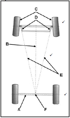
Labels:
- – Rear axle ✓
- – Longitudinal axis ✓
- – Front wheels ✓
- – Steering arms ✓
- – Extended centre lines from steering arms ✓
- – Intersection/Centre point✓
(Any 3 x 1) (3)
10.5 Purpose of Toe-out on turns:
The toe-out effect in a turn, gives a true rolling motion ✓ to the front wheels in a corner without scuffing. ✓ (2)
10.6 Wheel balancing pre-checks:
- The tyres for bruises, cracks and damaged side walls. ✓
- The wheel rims for damaged beads. ✓
- For foreign matter on rim and tyres.✓
- Tyre pressure. ✓
- Tyre thread wear. ✓
(Any 2 x 1) (2)
10.7 Purpose of catalytic convertor:
The catalytic convertor converts the pollutants ✓ in the exhaust gases of the engine into non – toxic substances making it environmentally friendly. ✓ (2)
10.8 Adaptive speed control:
- Maintain a speed as set by the driver. ✓
- Adapt this speed and maintain a safe distance from the vehicle in front.✓
- Provide a warning if there is a risk of a collision. ✓
- Prevent driver fatigue. ✓
- To control the set speed. ✓
- Improve fuel economy. ✓
- A constant controlled speed setting prevents speeding fines. ✓
(Any 3 x 1) (3)
10.9 Function of slip-ring and brush assembly:
Provide a moveable connection ✓ in order to allow current flow. ✓ (2)
10.10 Diode symbol: (2)
10.11 Advantages of electric fuel pump:
- Immediate supply of fuel when the ignition switch is turned on. ✓
- Low operation noise. ✓
- Less discharge pulsation of fuel. ✓
- Compact and lighter design. ✓
- Characterised to prevent fuel leak and vapour lock. ✓
- Delivers fuel at higher pressures. ✓
- Can be placed anywhere in the fuel line. ✓
(Any 2 x 1) (2)
[32]
TOTAL: [200]