ELECTRICAL TECHNOLOGY(POWER SYSTEMS) GRADE 12 MEMORANDUM - NSC PAST PAPERS AND MEMOS NOVEMBER 2019
Share via Whatsapp Join our WhatsApp Group Join our Telegram GroupELECTRICAL TECHNOLOGY: POWER SYSTEMS
GRADE 12
NATIONAL SENIOR CERTIFICATE
MEMORANDUM
NOVEMBER 2019
INSTRUCTIONS TO THE MARKERS
- All questions with multiple answers imply that any relevant, acceptable answer should be considered.
- Calculations:
2.1 All calculations must show the formulae.
2.2 Substitution of values must be done correctly.
2.3 All answers MUST contain the correct unit to be considered.
2.4 Alternative methods must be considered, provided that the correct answer is obtained.
2.5Where an incorrect answer could be carried over to the next step, the first answer will be deemed incorrect. However, should the incorrect answer be carried over correctly, the marker has to re-calculate the values, using the incorrect answer from the first calculation. If correctly used, the candidate should receive the full marks for subsequent calculations.
2.6 Markers should consider when and where a candidate has rounded off in a calculation, as well as the subsequent effect it has on the final answer obtained. The calculation should therefore be awarded marks on merit. - These marking guidelines are only a guide with model answers. Alternative interpretations must be considered and marked on merit. However, this principle should be applied consistently throughout the marking session at ALL marking centres.
QUESTION 1: OCCUPATIONAL HEALTH AND SAFETY
1.1
- An employee with a sense of teamwork helps a team to meet its goals.
- Teamwork helps a team deliver quality work.
- Teamwork can win the respect of your co-workers.
- Working together as a team can improve discipline in the workshop.
- Teamwork will lead to improved productivity. (2)
1.2
1.2.1 The purpose of the Act is to:
- Provide for health and safety of persons at work.
- Protect against hazards arising from the activities of other people at work.
- Establish an advisory council for occupational health and safety and related matters.
- Provide for health and safety for persons in connection with the use of plant and machinery (2)
1.2.2 Workplace can be defined as any premises or place where a person performs work ü during the time of his employment. (2)
1.3
1.3.1 Employee. Learner, Supervisor, Team leader, Safety representative (1)
1.3.2 Health and safety representative. ü Inspector. (1)
1.4
- Remain calm.
- Stop whatever you are doing.
- Switch off machinery.
- Notify a responsible adult or teacher.
- If there is an emergency stop nearby activate it if necessary.
- Move in an orderly manner to the nearest assembly point.
NOTE: Procedure can be listed in any order (2)
[10]
QUESTION 2: RLC CIRCUITS
2.1
2.1.1 Power factor is the ratio of the true power to the apparent power.
NOTE: If the formula is written 1 mark must be awarded (2)
2.1.2 The quality factor of an inductor refers to the ratio of the inductor's reactance to its internal resistance during resonance.
If the formula is written 1 mark must be awarded
The ratio of the inductive/capacitive voltage to the supply voltage during resonance
The ratio of the inductive/capacitive reactance to the impedance during resonance (2)
2.2
- Wattless voltage dividers
- Timing circuits
- Filter circuits
- Oscillating circuits
- Radio-tuning circuits (2)
2.3
2.3.1 VT = √VR2 + (VC - VL)2
= √122 + (24 - 16)2
= 14.42V (3)
2.3.2 XL = V L
I
= 16
3
= 5.33Ω (3)
2.3.3 The circuit is capacitive because the voltage drop across the capacitor is greater than the voltage across the inductor.
NOTE: If XL and XC are calculated and stated as a capacitive circuit, 2 marks should be awarded.
If the learner wrote, the circuit is inductive, but give the same reason, that motivation is deemed incorrect.(2)
2.3.4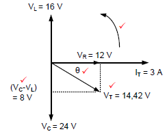
NOTE: No label, no marks (4)
2.3.5 When the impedance of the circuit is increased, the power factor will decrease therefore increasing the value of the phase angle. (2)
2.4
2.4.1 IT = √IR2 +(IL - Ic)2
= √62 +(4 - 3)2
= 6.08A (3)
2.4.2
Cosθ = I R
IT
θ = Cos-1 6
6.08
= 9.30 (3)
2.4.3 The phase angle is lagging because the inductive current is larger than the capacitive current.
NOTE: If only the second part of the answer is given = 1 mark (2)
2.5
2.5.1 At resonance XL = XC = 50 Ω
C = 1
2πfXc
= 1
2 x π x 2000 x 50
= 1.59µF (4)
NOTE: If the learner only substituted 50 Ω in the place of XC, the correct substitution will be awarded 2 marks
If the learner calculated the inductance first, and used the resonant frequency’s formula to work out the capacitance full marks must be awarded.
L= XL
2 × πf
L= 50
2×π×(2000)
L= 3,98×10⁻³H
fr= 1
2π√LC
2000= 1
2π√3.97 x 10⁻³ x C
2000(2π√3.97 x 10⁻³ x C) = 1
C = 1.6μF
2.5.2 At resonance R = Z = 12Ω
I = VT
Z
= 120
12
= 10A (4)
If R is used in the place of Z, full marks are awarded
2.5.3 If the resistance is doubled, the current will be halved. (1)
2.5.4 Z = R
VL = VC
VR = VT
XL = XC
Cosθ = 1
θ = 0º
I = maximum
Z = minimum (3)
[40]
QUESTION 3: THREE-PHASE AC GENERATION
3.1
- Less current used.
- Reduced monthly bill.
- Reduced heat generated by equipment that could then last longer.
- Reduced maintenance. (3)
3.2 To supply consumers with both single phase ü and three phase power as needed.
To supply a neutral and earth point. (2)
3.3 A wattmeter is an instrument for measuring the electric power dissipated by a load.
Kilowatt-hour meter (energy meter) is an instrument for measuring an amount of power consumed over a period of time.
Kilowatt-hour meter is an instrument for measuring the energy consumed. (2)
3.4
3.4.1 The National Grid transmits electrical power to the customer. (1)
3.4.2 The National control centre monitors and controls the National Grid. (1)
3.5
3.5.1
VY or VL2 or L2 or yellow phase
VB or VL3 or L3 or blue phase (2)
3.5.2 120° (1)
3.6
3.6.1
Pin = P out x 100
η
=25000 x 100
85
= 29411.76W
= 29.41kW
= 29.41 x 10³W (3)
3.6.2 P = √3 x VL x IL Cosθ
IL= 29411.76
√3×380×0,87
=51,36 A
OR
P= √3×VL×IL×cosθ×η
??= Pout
√3×VL×cosθ×η
IL= 25 000
√3×380×0,87×0,85
IL=51,36 A (3)
3.6.3 IPH = IL
=51,36 A (2)
3.7
3.7.1 Two wattmeter method. (1)
3.7.2 PT = P1 + P2
=14000 + 18000
= 32000W (3)
OR
PT = P1 + P2
=14k + 18k
= 32kW (3)
OR
PT = P1 + P2
=14 x 103 + 18 x 103
= 32 x 103W (3)
3.7.3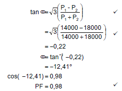 (3)
(3)
3.8 S= √3VLIL
IL = S
√3VL
= 20000
√3 x 220
= 52.5A (3)
NOTE: If the true power formula is used to correctly calculate the line current, full marks are awarded.
[30]
QUESTION 4: THREE-PHASE TRANSFORMERS
4.1 Overload
Lightning
Surges caused by external switching
Poor ventilation (3)
4.2 The earth fault will cause the phases to be unbalanced; This will lead to a difference in voltage between the phases. As a result the difference will activate the protective relay,ü isolating the transformer from the supply. (3)
4.3
- When the load increases the current drawn from the secondary winding of the transformer will also increase, ü
- The magneto motive force in the secondary windings will also increase. ü
- The result is that the primary magneto motive force increases ü because it is directly proportional counteracting the secondary load requirements,
- Keeping the input and output magneto motive force proportionally balanced. (3)
4.4 Air natural (AN).
Air Forced (AF). (2)
4.5 During the transformation process, losses occur and therefore the output power is less than the input power.(1)
4.6
- The coils are wound around all three core legs.
- The axis of the core type windings is normally vertical.
- The coils can be removed for maintenance.
NOTE: Drawing the transformer will show points 1 and 2 thus receiving 2 marks. (3)
4.7
4.7.1 TR = N p
Ns
= 600
80
= 7.5:1
= 8:1 (3)
4.7.2 VPh(P) = VL(p)
√3
= 6000
√3
= 3.46kV
= 3464V
= 3.46 x 10³V (3)
4.7.3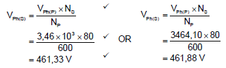 (3)
(3)
4.7.4 VL= VPh (Delta transformers)
VL= 461,88 V (2)
4.8 Mutual induction occurs when the magnetic field created in the primary windings link with the secondary windings when current flows thus inducing voltage in the secondary windings in line with Faradays law. (4)
[30]
QUESTION 5: THREE-PHASE MOTORS AND STARTERS
5.1
- Continuity test
- Insulation resistance between windings and earth.
- Insulation resistance between the coils of the motor.
- Check for loose connections in the terminal box. (3)
5.2 To protect electrical equipment from damage during fault conditions ü and to protect the operator of the equipment. (2)
5.3
5.3.1 Automatic sequence starter
Sequence starter with timer (2)
5.3.2
- The coil of MC1 will remain energised
- As result MC1NO2 will remain closed
- In the main circuitü L1, L2, L3, T1, T2, T3 will all remain closed (4)
5.3.3
- When the Start button is pressed, the coil of contactor MC1 will energise.
- The contact MC1 N/O1 will close keeping MC1 energised after the Start button is released.
- At the same time, MC1 N/O2 closes, thus energising the coil of the timer contactor (T).
- The timer will time through after a pre-determined time, T N/O will close energising MC2 (4)
5.3.4 The main function of MC1 is to electrically control ü heavy current devices safely. (2)
5.4 To prevent unnecessary tripping of the overload relay at start-up.
The starting current is reduced when starting the motor, to prevent overcurrent in the motor and prevent cables from overheating or burning out.(2)
5.5
5.5.1 S(Papp) = √3 x VL x IL
= √3 x 380 x 29
= 19.09 kVA
OR
S(Papp) = √3 x VL x IL
= √3 x 380 x 29
= 19087.19VA
= 19.08 x 10³ VA (3)
OR
S = P
Cosθ
= 16000
0.85
= 18823.53VA
5.5.2 Number of poles = 12
poles per phase = 12 = 4
3
pole pairs = 2
NOTE: If 2 is replaced correctly in the place of p, full marks are awarded
ns =60 x f
p
=60 x 50
2
= 1500 rpm (5)
5.5.3 S = ns - nr x 100
ns
= 1500 - 1400 x 100
1500
= 6.7% (3)
[30]
QUESTION 6: PROGRAMMABLE LOGIC CONTROLLERS (PLCs)
6.1
6.1.1 Relay logic or relay circuits. (1)
6.1.2
- Maintain a single ground for the PLC.
- Keep the wire length short.
- Ensure that a main cut-off switch is fitted.
- Use the correct size of wire of at least 2 mm2.
- The supply must be fitted with a circuit breaker or a fuse.
- Each sub-circuit must be fitted with its own current protection. (3)
6.2 Software is the machine language that is installed on a computer or written into a PLC's control program that instructs it to interact with its input and output hardware. (3)
6.3 To protect against power surges such as lightning strikes, that may damage the PLC unit. (2)
6.4
6.4.1 A sensor is a device that detects an environmental condition and changes its characteristics which can be used to influence other devices.
NOTE: Although the response in the prescribed textbook is incorrect it will be accepted. (2)
6.4.2
- Proximity sensor
- Temperature sensor
- Light sensor
- Overload sensor (3)
6.4.3 To monitor the level of liquid (i.e. water in rivers and dams, petrol and diesel in car tanks reaches a certain level) When either low or high it sends a signal or activates an alarm for attention. (1)
6.4.4 An analogue device detects continuously changing states ü and provides an analogue signal within a certain range. (2)
6.5
6.5.1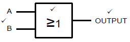
1 mark for the two inputs A and B
1 mark for the output
1 mark for the correct gate symbol
If the incorrect symbol is drawn = 0 (3)
OR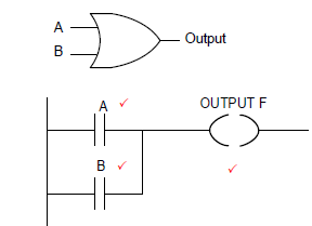
6.5.2 2 marks = inputs A and B
1 mark = correctly labelled output (F)
Although output F is drawn incorrect in the prescribed textbook, it will be accepted. (3)
6.5.3 A + B = Output (F)
OR-gate = 2 marks (2)
6.6
6.6.1 An OFF-delay timer contact (1)
6.6.2
- When the push button (I1) is pressed, the Timer will be energised.
- The normally open contact of the Timer will close
- The output (Q) will be at high state.
- The output will remain at that state for 10 seconds ü and thereafter, it will be at low state until the push button is pressed again.
NOTE: If 6.6.1 was identified as an ON-delay and thereafter explain the ON-delay correctly in 6.6.2 = 5 marks. (5)
6.7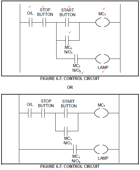
(7)
OR
6.8
6.8.1 The purpose of the first stage is to convert AC voltage supply to DC voltage by rectification using each pair of diodes. (2)
6.8.2 For each pair of switches, one switch controls the positive half cycle of the output voltage, while the other switch controls the negative half cycle of the output voltage, thus controlling the time that each switch is on. (2)
6.8.3 If the switch remains ON for longer, the output waveform will be higher/longer and the frequency will be lower, thus the motor will turn slower (2)
6.9
6.9.1
- Improves energy usage by controlling the power that is fed into the motor.
- Reduce motor wear.
- Better process control, such as speeding up or slowing down a motor process depending on the type of production and processes.
- It can convert a fixed-frequency and fixed voltage to a variable frequency and variable voltage. (3)
6.9.2
- Variable air volume air conditioning systemü
- Exhaust systems
- Fan systems
- Water pumping systems
- Heating systems
- Battery powered electric cars (1)
6.9.3
- Volts-per-Hertz (V/Hz) drive control
- Vector control
- Direct torque control (DTC)
- Pulse width Modulation control (PWM) (3)
6.10
6.10.1 Cranes
Electrical locomotives or trains
Battery powered electrical vehicle (3)
6.10.2 By using the motor as a generator ü to convert mechanical energy into electrical energy. (2)
6.11
6.11.1 Breakdown speed. (1)
6.11.2
- At start up the torque is at 200%.
- When the speed increases the torque will increase up to point A,
- Thereafter torque will decrease as the motor speed increases further.
- The motor is accelerated from start to a region above the breakdown speed by the adjustable speed drive. (3)
[60]
TOTAL: 200