ELECTRICAL TECHNOLOGY(POWER SYSTEMS) GRADE 12 QUESTIONS - NSC PAST PAPERS AND MEMOS NOVEMBER 2019
Share via Whatsapp Join our WhatsApp Group Join our Telegram GroupELECTRICAL TECHNOLOGY: POWER SYSTEMS
GRADE 12
NATIONAL SENIOR CERTIFICATE
NOVEMBER 2019
INSTRUCTIONS AND INFORMATION
- This question paper consists of FIVE questions.
- Answer ALL the questions.
- Answer the following questions on the attached ANSWER SHEETS:
QUESTIONS 2.1.2, 2.4.2, 2.6.2 and 2.7.3
QUESTIONS 4.2.2, 4.3.3, 4.4.2, 4.5.1 and 4.5.2 - Write your CENTRE NUMBER and EXAMINATION NUMBER on every ANSWER SHEET and hand them in with your ANSWER BOOK, whether you have used them or not.
- Sketches and diagrams must be large, neat and FULLY LABELLED.
- Show ALL calculations and round off answers correctly to TWO decimal places.
- Number the answers correctly according to the numbering system used in this question paper.
- You may use a non-programmable calculator.
- Calculations must include:
9.1 Formulae and manipulations where needed
9.2 Correct replacement of values
9.3 Correct answer and relevant units where applicable - A formula sheet is attached at the end of this question paper.
- Write neatly and legibly.
QUESTION 1: OCCUPATIONAL HEALTH AND SAFETY
1.1 Describe how teamwork improves work ethics. (2)
1.2 With reference to the Occupational Health and Safety Act, 1993 (Act 85 of 1993):
1.2.1 State TWO purposes of the Occupational Health and Safety Act, 1993 (Act 85 of 1993). (2)
1.2.2 Define the term workplace. (2)
1.3 An employer has a duty to report on occupational health and safety and related matters. Name ONE person they should inform when:
1.3.1 The allocated task is hazardous (1)
1.3.2 A major incident occurs (1)
1.4 State TWO general emergency procedures to be followed when the emergency siren is sounded at school. (2)
[10]
QUESTION 2: RLC CIRCUITS
2.1 Define the following with reference to RLC circuits:
2.1.1 Power factor (2)
2.1.2 Q-factor of an inductor in a resonant circuit (2)
2.2 State TWO applications of RLC circuits. (2)
2.3 FIGURE 2.3 below shows an RLC series circuit. Answer the questions that follow.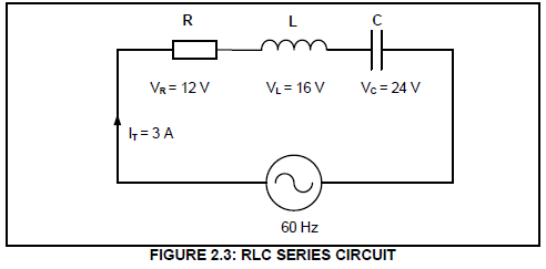
Given:
IT = 3 A
VR = 12 V
VL = 16 V
VC = 24 V
f = 60 Hz
2.3.1 Calculate the total voltage of the supply.(3)
2.3.2 Calculate the value of the inductive reactance.(3)
2.3.3 State if the circuit is capacitive or inductive. Motivate your answer.(2)
2.3.4 Complete the phasor diagram on the ANSWER SHEET for QUESTION 2.3.4 and show the direction of rotation.(4)
2.3.5 Describe how an increase in impedance, while keeping the resistance constant, will affect the phase angle and the power factor.(2)
2.4 FIGURE 2.4 below shows an RLC parallel circuit consisting of a 20 Ω resistor, an inductor with an inductive reactance of 30 Ω and a capacitor with a capacitive reactance of 40 Ω, all connected across a 120 V/60 Hz supply.
Answer the questions that follow.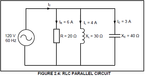
Given:
R = 20 Ω
XL = 30 Ω
XC = 40 Ω
VT = 120 V
f = 60 Hz
2.4.1 Calculate the total current in the circuit.(3)
2.4.2 Calculate the phase angle.(3)
2.4.3 State whether the phase angle is leading or lagging. Motivate your answer.(2)
2.5 FIGURE 2.5 below shows an RLC series resonant circuit which consists of a 12 Ω resistor, an inductor with an inductive reactance of 50 Ω and a variable capacitor, all connected across a 120 V/2 kHz supply. Answer the questions that follow.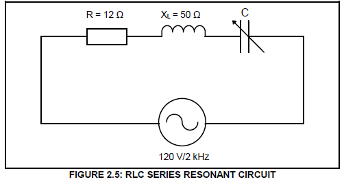
Given:
VT = 120 V
f = 2 kHz
R = 12 Ω
XL = 50 Ω
2.5.1 Calculate the value of C when the circuit resonates at 2 kHz.(4)
2.5.2 Calculate the value of the current in the circuit.(4)
2.5.3 State how current will be affected if the value of the resistance is doubled.(1)
2.5.4 List THREE characteristics of an RLC series circuit at resonance. (3)
[40]
QUESTION 3: THREE-PHASE AC GENERATION
3.1 List THREE advantages of power factor improvement for the consumer.(3)
3.2 Explain why the power distribution to consumers is connected in star.(2)
3.3 State the difference between a wattmeter and a kilowatt-hour meter.(2)
3.4 State the purpose of the following:
3.4.1 National power grid(1)
3.4.2 Eskom's national control centres(1)
3.5 Refer to FIGURE 3.5 below and answer the questions that follow.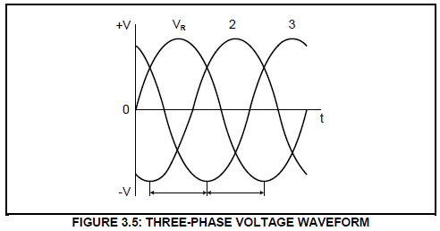
3.5.1 Label the generated voltage waveforms marked 2 and 3 according to the universally adopted sequence.(2)
NOTE: Take VR as reference.
3.5.2 Name the phase displacement between the three waveforms generated in FIGURE 3.5. (1)
3.6 A 380 V three-phase, star-connected AC motor has an output power of 25 kW and it operates at a lagging power factor of 0,87. The efficiency of the motor is 85%.
Given:
VL = 380 V
ƞ = 85%
Cos ө = 0,87 lagging
Pout = 25 kW
Calculate the:
3.6.1 Input power(3)
3.6.2 Line current(3)
3.6.3 Phase current(2)
3.7 Refer to FIGURE 3.7 below and answer the questions that follow.
Given:
P1 = 14 kW
P2 = 18 kW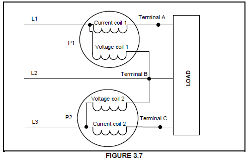
3.7.1 Identify the method used in FIGURE 3.7 to measure the power to the load.(1)
3.7.2 Calculate the total power used by the load.(3)
3.7.3 Calculate the power factor of the system.(3)
3.8 A delta-connected three-phase load is supplied by a 20 kVA generator with a phase voltage of 220 V. The power factor of the load is given as 0,85 lagging. Calculate the line current at full load.
Given:
S = 20 kVA
VPH = 220 V
PF = 0,85 (3)
[30]
QUESTION 4: THREE-PHASE TRANSFORMERS
4.1 List THREE external conditions that may cause transformer failure.(3)
4.2 Explain what would happen if an earth fault occurs in one of the three phases of a protected transformer.(3)
4.3 Describe how an increase in the load would affect the magneto motive force in the primary windings.(3)
4.4 Name TWO types of cooling methods for a dry transformer.(2)
4.5 State why the output power of a transformer is slightly less than the input power.(1)
4.6 Describe the construction of a three-phase core-type transformer.(3)
4.7 A star-delta connected transformer has 600 turns in the primary windings and 80 turns in the secondary windings. The transformer is connected to a 6 kV supply.
Given:
NP = 600 turns
NS = 80 turns
VL(P) = 6 kV
Calculate the:
4.7.1 Turns ratio(3)
4.7.2 Primary phase voltage(3)
4.7.3 Secondary phase voltage(3)
4.7.4 Secondary line voltage(2)
4.8 With reference to Faraday's law, describe how mutual induction occurs in a transformer. (4)
[30]
QUESTION 5: THREE-PHASE MOTORS AND STARTERS
5.1 List THREE electrical inspections that need to be carried out on a three-phase motor before commissioning it.(3)
5.2 Describe why it is necessary to have protective devices as part of motor control.(2)
5.3 Study FIGURE 5.3 below and answer the questions that follow.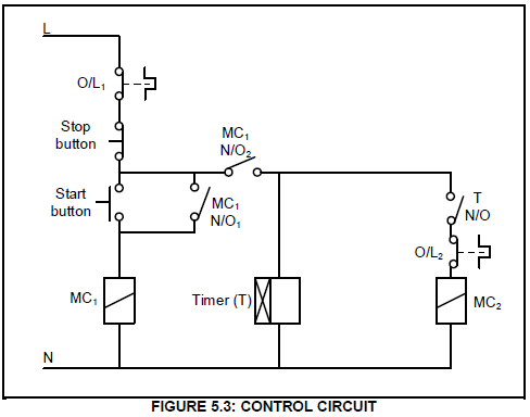
5.3.1 Identify the motor starter in FIGURE 5.3.(2)
5.3.2 Describe what would happen to contactor MC1 if contact MC1 N/O1 was faulty and permanently closed.(4)
5.3.3 Describe the starting sequence of the control circuit.(4)
5.3.4 Describe the main function of contactor MC1.(2)
5.4 Explain why the starting current is reduced in a star-delta motor starter. (2)
5.5 A 16 kW three-phase star-connected motor with 12 poles, is connected across a 380 V/50 Hz supply and draws a phase current of 29 A with a power factor of 0,85.
Given:
Number of poles = 12
Cos θ = 0.85
POUT = 16kW
VL = 380V
IPH = 29A
f = 50Hz
Calculate the:
5.5.1 Apparent power(3)
5.5.2 Synchronous speed(5)
5.5.3 Percentage slip if the rotor speed is 1 400 r/min(3)
[30]
QUESTION 6: PROGRAMMABLE LOGIC CONTROLLERS (PLCs)
6.1 With reference to PLCs:
6.1.1 Name the system used for automated machine control for industrial production before PLCs were developed.(1)
6.1.2 State THREE health and safety issues to consider, other than anti-surge protection, when working with PLC equipment and installations.(3)
6.2 Explain the term software with reference to the operation of a PLC.(3)
6.3 Explain why it is important to install anti-surge protection when working with PLCs.(2)
6.4 With reference to the input devices of PLCs:
6.4.1 Define the term sensor.(2)
6.4.2 List THREE types of sensors other than a level sensor.(3)
6.4.3 State an application of a level sensor.(1)
6.4.4 Describe the function of an analogue device.(2)
6.5 Refer to FIGURE 6.5 below and answer the questions that follow.
| Input A | Input B | Input A |
| 0 | 0 | 0 |
| 0 | 1 | 1 |
| 1 | 0 | 1 |
| 1 | 1 | 1 |
6.5.1 Draw the logic gate symbol that this truth table represents.(3)
6.5.2 Draw the ladder logic diagram that this truth table represents.(3)
6.5.3 Write the logic function of FIGURE 6.5.(2)
6.6 FIGURE 6.6 below shows a PLC logic program with a time delay of 10 seconds. Answer the questions that follow: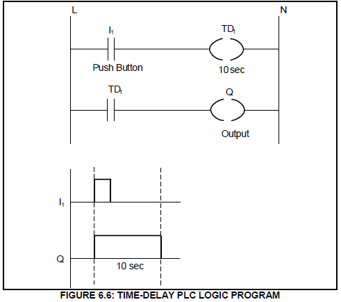
6.6.1 State whether the logic program uses an ON-delay timer contact or an OFF-delay timer contact.(1)
6.6.2 Describe the sequential operation of the logic program when the push button (I1) is pressed.(5)
6.7 Draw a ladder logic diagram that will execute the same function as the control circuit in FIGURE 6.7 below.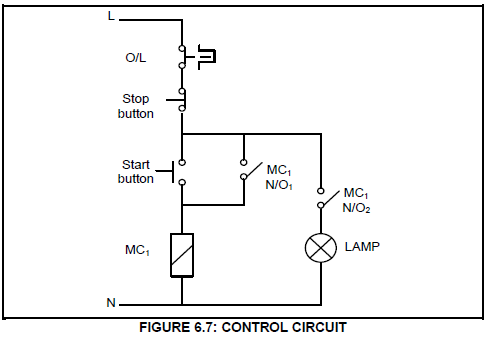
6.8 FIGURE 6.8 below shows a variable frequency drive (VFD) circuit. Study the circuit and answer the questions that follow: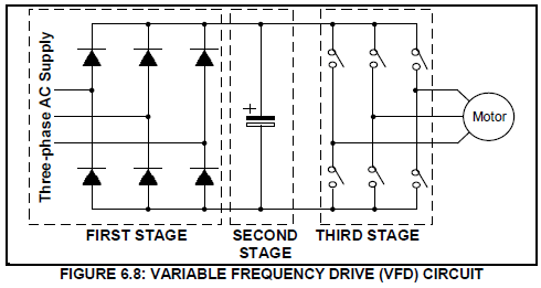
6.8.1 Describe the purpose of the first stage of the VFD circuit.(2)
6.8.2 Explain how speed control is achieved by using the switches in the third stage.(2)
6.8.3 Explain how the output waveform and the frequency of the supply will be affected if the switches remain 'ON' for a longer period.(2)
6.9 With reference to the use of the VFD to control the speed of a motor, answer the following questions:
6.9.1 State THREE production advantages for industries and manufacturers when using a VFD to control the speed of a motor.(3)
6.9.2 Name ONE application of a VFD.(1)
6.9.3 List THREE VFD methods that can be used to control the speed of a motor.(3)
6.10 With reference to the regenerative braking process:
6.10.1 Give THREE examples where regenerative braking is applied other than in lifts.(3)
6.10.2 Explain how regenerative braking is achieved.(2)
6.11 FIGURE 6.11 below shows the characteristic curve of speed versus torque when the VFD is used to control the speed of a three-phase induction motor.
Study the characteristic curve and answer the questions that follow.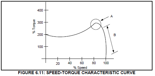
6.11.1 Name region A. (1)
6.11.2 Describe the start up and run profile of the induction motor in FIGURE 6.11. (3)
[60]
TOTAL: 200