AGRICULTURAL TECHNOLOGY GRADE 12 MEMORANDUM - NSC PAST PAPERS AND MEMOS NOVEMBER 2019
Share via Whatsapp Join our WhatsApp Group Join our Telegram GroupAGRICULTURAL TECHNOLOGY
GRADE 12
MEMORANDUM
NATIONAL SENIOR CERTIFICATE
NOVEMBER 2019
SECTION A
QUESTION 1
1.1
1.1.1 A✓✓(2)
1.1.2 B✓✓(2)
1.1.3 D✓✓(2)
1.1.4 C✓✓(2)
1.1.5 C✓✓(2)
1.1.6 A✓✓(2)
1.1.7 A✓✓(2)
1.1.8 A✓✓(2)
1.1.9 D✓✓(2)
1.1.10 B✓✓(2)
[20]
1.2
1.2.1 Penetrable/spongy/permeable✓✓(2)
1.2.2 Round/Cylindrical/Vermeer✓✓(2)
1.2.3 Hammers/Rotor✓✓(2)
1.2.4 Oil/Hydraulic✓✓(2)
1.2.5 Negative(Accept any relevant word to ‘negative’)✓✓(2)
[10]
1.3
1.3.1 A, E or H✓✓(2)
1.3.2 A✓✓(2)
1.3.3 A, E or H✓✓(2)
1.3.4 C✓✓(2)
1.3.5 B✓✓(2)
[10]
TOTAL SECTION A: 40
QUESTION 2: MATERIALS AND STRUCTURES
2.1
2.1.1 The metal that can effectively be used for soldering.
Copper/Brass/stainless steel/ mild steel✓ (1)
2.1.2 The metal that will be the best for installation of warm water pipes in a farm house.
Copper✓ (1)
2.1.3 The material that is used to manufacture foil that is used to cover food.
Aluminium✓ (1)
2.1.4 THREE reasons why stainless steel is the best material that can be used to manufacture food processing equipment.
- It is resistant against corrosion.✓
- It is harder than steel/tensile strength.✓
- It is resistant against air, water and chemical acids and alkali.✓
- Heat resistance. ✓
- Can absorb shock and vibration.✓
- Easy to clean. ✓
- Neutral to food.✓
- Food lasts longer.✓
- Does not contaminate food✓ (3)
2.2 THREE factors that you must consider when identifying tin.
- When heated in air, tin forms tin oxide (stannic oxide) which is feeble acidic✓
- Pure white tin slowly tends to become grey powder.✓
- Tin is a silvery-white, soft, malleable metal that can be highly polished✓
- Tin has a crystalline structure and when a tin bar is bent, a 'tin cry' is heard, due to the breaking of these crystals.✓
- It resists oxygen and water but dissolves in acids and bases.✓
- Exposed surfaces form an oxide film.✓ (Any 3) (3)
2.3 TWO advantages of a tin/copper alloy compared to pure copper.
- The alloy becomes harder than copper.✓
- It is more easily casted than copper.✓
- Strength.✓ (2)
2.4 TWO properties of bronze.
- Bronze resists corrosion. (especially seawater corrosion)✓
- Resists metal fatigue more than steel.✓
- Better conductor of heat and electricity than most steels.✓
- High electrical conductivity.✓
- Low-friction properties of bearing bronze.✓
- Resonant qualities of bell bronze.✓
- Bronze is a solid at room temperature.✓
- Bronze is copper-coloured.✓
- Bronze is odourless.✓
- Bronze has melting point of ~950 degrees Celcius to 1050 Degrees Celcius.✓
- Bronze is ductile.✓
- Bronze has low friction properties.✓
- Lasts longer
Brownish red in color. ✓ (2)
2.5 TWO important aspects that must be considered when an adhesive is to be chosen for a specific application.
- Type of material to be joined✓
- Conditions under which this joint will be used.✓ (2)
2.6 FOUR precautionary measures that must be taken into account when working with glass fibre.
- Catalyst and accelerator should always be stored separately. (Explosion) ✓
- Remove all resin catalyst and accelerator from skin✓
- Wear gloves if skin is sensitive.✓
- Use acetone in well ventilated room.✓
- Handle resin casting carefully they are brittle.✓
- Glass fibre matting has small pieces of fibre that can penetrate the skin.✓
- Don't breath in glass fibre or get it in your eyes.✓ (Any 4) (4)
2.7 FOUR properties of Vesconite that makes it suitable to be used in marine applications.
- Vesconite has the lowest rates of wear. Even in dirty and un-lubricated conditions.✓
- Vesconite gives long life with low maintenance and low friction.✓
- Vesconite is ideal for many marine applications. Water is an excellent lubricant for Vesconite.✓
- Vesconite is dimensionally stable/strong.✓
- Vesconite will not swell and seize or soften and wear under water like nylon✓
- Vesconite's internal lubricants make it well suited to upper rudder bearing applications where there are long periods between greasing.✓
- Long wear life. Vesconite gives up to ten times the service life of phosphor bronze in poorly lubricated conditions.✓
- Vesconite bearings may be machined to the correct clearance without fear of swelling.✓
- Easy to remove and replace.✓ (Any 4) (4)
2.8
2.8.1 Explanation of the function of the electric wires shown by arrow A.
The function of the wires is to connect both the positive and the negative wires adjacent to the gate to the wires on the other side of the gate ✓so that there is a continuous circuit in the fence when the gate is opened. ✓ (2)
2.8.2 Name of the component of the electric fence shown by arrow B and an explanation of its function.
Earth return spike/Ground spike.✓
The negatively charged spike creates a path through the ground when an animal touches the positive wires of the fence. The animal is the missing link in order to complete the loop.✓ (2)
2.8.3 FOUR safety precautions applicable to electric fencing on the farm.
- Install warning signs.✓
- No barbed wire must be electrified.✓
- Electric fences shall be installed and operated so that they cause no electrical hazard to persons, animals or their surroundings.✓
- Electric fence constructions, which are likely to lead to entanglement of animals or persons, shall be avoided.✓
- An electric fence shall not be supplied from more than one energizer.✓
- Current/amperage not be higher than 0,002 Amp.✓
- Voltage not to be higher than 10 000 Volts.✓
- The gap between two separate electric fences with different energizers shall be at least 2 m.✓
- If this gap is to be closed, this should be affected by means of an electrically non-conductive material.✓ (Any 4) (4)
2.8.4 The procedure that must be followed when the earth system of an electric fence is being tested.
- Firstly short out the live fence line to ground.✓
- Switch the energizer ON.✓
- Measure the voltage between the ground and the earth spike with a meter✓
- If this is above 200 volts the earth installation is inefficient.✓
- Check the connections or increase the number of earth spikes.✓
- If you get a shock from the earth spike before you short the fence line, then there is a poor Earth AND possibly a fault on the fence line as well. (Check for vegetation on the line or faulty insulators).✓ (4)
[35]
QUESTION 3: ENERGY
3.1
3.1.1 Explanation of how electricity is generated with the solar panel.
- There needs to be some form of solar cell or panel.✓
- The solar panels are made of a semi conductive material; the most common material is silicon.✓
- The semi-conductive material contains electrons which are quite happy just sitting there.✓
- When photons (contained within the sun's rays) hit the solar cells, ✓ the electrons absorb this solar energy, transforming them into conduction electrons.✓
- If the energy of these photons is great enough, then the electrons are able to become free, and carry an electric charge through a circuit to the destination.✓ (5)
3.1.2 FOUR possible reasons for a solar panel not working to its full potential.
- Some electrons may be lost.✓
- When the electrons release heat; the panel also becomes warm, interfering with other aspects of the solar cells.✓
- Number of solar panels determines the efficiency of the system.✓
- Expensive technology produces energy more efficient than cheaper ones.✓
- Location of installation.✓
- Objects blocking the sun's rays.✓ (Any 4) (4)
3.2 Explanation of the working of a geothermal power station from the moment that a geo thermal energy source is discovered to the point that electricity is delivered by the power station.
- Deep holes are drilled into the earth into the geothermal hot spot.✓
- A pipe is installed inside the hole which allows hot steam to rise up to the surface.✓
- The pressurized steam is then channelled to a turbine which begins to turn under the force of the steam.✓
- This turbine is linked to the generator and so the generator also begins to turn, generating electricity.✓
- The cool water is then pumped down a new pipe where the water is again heated by the earth and then sent back up the first pipe to repeat the process.✓ (5)
3.3 THREE advantages that wind as an alternative energy source has to a farmer that has no access to the national electricity grid.
- Wind power has no fuel costs.✓
- Low or negligible maintenance costs.✓
- Wind power has no clean-up costs.✓
- Wind energy has no carbon tax costs.✓
- Farmer can produce his/her own electricity for powering electric equipment.✓ (Any 3) (3)
3.4 TWO types of vegetable oils that can economically be used to manufacture bio-fuels.
- Soya oil.✓
- Canola oil.✓
- Sunflower oil.✓
- Peanut oil.✓
- Pecan nut oil.✓
- Avocado pear oil ✓ (Any 2) (2)
3.5 The alternative fuel that can be manufactured from methane gas to supplement gasoline.
Methanol.✓ (1)
[20]
QUESTION 4: SKILLS AND CONSTRUCTION PROCESSES
4.1
4.1.1 The steps that must be followed when replacing the damaged contact tip on the MIG handset.
- Unscrew the welding shield cup.✓
- Unscrew the bad welding tip.✓
- Slide a new tip into place.✓
- Screw the new tip on.✓
- Replace the welding cup.✓(5)
4.1.2 THREE disadvantages of MIG welding.
- Higher initial setup cost.✓
- No gas, no welding.✓
- Harmful fumes.✓
- Difficult to move around✓
- Atmosphere surrounding the welding process has to be stable (hence the shielding gasses); therefore this process is limited to draught free conditions.✓
- Higher maintenance costs due to extra electronic components✓
- The setting of plant variables requires a high skill level.✓
- Less efficient where high duty cycle requirements are necessary.✓
- Radiation effects are more severe✓ (Any 3) (3)
4.2
4.2.1 Neatness of sketch.✓(1)
4.2.2 Any Applicable measurement.✓(1)
4.2.3 Any Applicable welding joint.✓(1)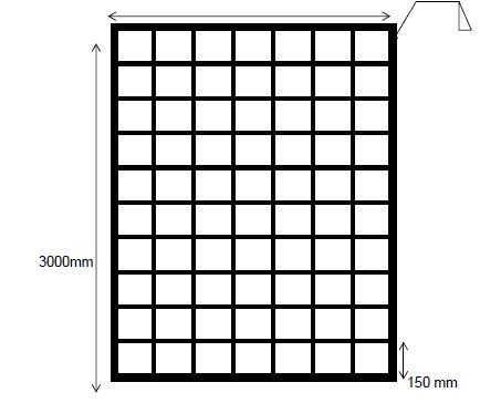
4.2.4 Material list.
Pflat bar 2 of 3 000mm = 6m✓
2 of 2 100mm = 4,2m✓
= 10,2m
Round bar 13 of 3 000mm = 39m✓
19 of 2 100mm = 39.9m✓
78,9m(4)
4.2.5 Cost.
Flat barl. 10,2m x R5 = R51,00✓
Round bar 78,9m x R3 = R236,70✓
Total cost = R287,70✓ (3)
4.3 Explanation of the term hard-facing of a worn part.
- It is the process by which worn parts can be built up by padding with a wear resistant metal.✓
- The type of hard-facing and type of electrode used are determined by the service requirements of the parts concerned.✓ (2)
4.4 Description of the overhead arc welding process from the moment that the arc is struck.
- Use an arc as short as possible.✓
- When molten metal starts dripping, the amperage should be reduced slightly.✓
- Move electrode slightly faster.✓
- Hold electrode in same position as in relation to the base metal.✓
- Weld a number of runs without any lateral movement.✓
- Chip away slag and clean the weld.✓ (Any 5) (5)
4.5
4.5.1 FOUR advantages of the plasma cutting apparatus.
- Faster cutting speed.✓
- Wide range of materials and thickness.✓
- Easy to utilize✓
- Economical✓ (4)
4.5.2 Description of the cutting process when using an oxy-acetylene apparatus.
- First bring the material up to red hot.✓
- Oxygen is then fed with the lever on the cutting attachment.✓
- The steel actually ignites giving of more heat to keep the process going.✓
- The steel turns into a liquid.✓
- The iron liquid is cleared from the cut by pressure from the oxygen stream.✓ (Any 3) (3)
4.5.3 THREE types of metals that can be cut with an oxy-acetylene cutting apparatus.
- Mild steel.✓
- Cast iron/Iron.✓
- Stainless steel.✓ (3)
[35]
QUESTION 5: TOOLS, IMPLEMENTS AND EQUIPMENT
5.1 FIVE safety precautions regarding the use of a ride on rotary lawn mower.
- Read and understand the operator's manual.✓
- Remove all debris from lawns before mowing.✓
- Use recommended PPE.✓
- Disengage the blade before starting.✓
- Keep all guards and safety shields in place✓
- Never disengage any safety interlock switches.✓
- Never refuel the mower when the engine is hot or running✓
- Store gasoline in an approved container with proper label.✓
- Turn off the motor before cleaning the area under the deck.✓
- Do not allow bystanders and children near the machine.✓ (Any 5) (5)
5.2
5.2.1 Part fitted between the tractor and the baling machine.
PTO (Power Take Off shaft)✓ (1)
5.2.2 Description of the maintenance of the baling machine at the end of the baling season.
- Remove all bales from baling chamber.✓
- Clean the baler properly.✓
- Drain and replace all oil.✓
- Releases the tension on all drive belts.✓
- Remove all chains, clean and oil them, and replace them.✓
- Dismantle all slip clutches, clean them and reassemble them but do not put the springs under tension.✓
- Totally reduce bale chamber tension.✓
- Cover all unpainted areas with a thin layer of grease.✓
- Grease all grease nipples.✓
- Store baler in a dry place under cover.✓ (Any 5) (5)
5.2.3 Description of the working and construction of the universal joint that is installed in the drive mechanism of the baling machine.
- It allows the shaft to work at an angle.✓
- It is commonly used in shafts that transmit rotary motion.✓
- It consists of a pair of hinges located close together, oriented at 90° to each other, connected by a cross shaft.✓ (3)
5.2.4 The type of hydraulic cylinder that will be suitable for the lifting and lowering of the machine's pick-up wheel with a motivation.
- A double acting cylinder.✓
- This type of cylinder allows both push and pulls forces✓ to lower or lift the pick-up wheel✓ (3)
5.3
5.3.1 The function of the bearing shown.
- Constrains relative motion between moving parts.✓
- Provides for free linear movement of the moving part.✓
- For free rotation around a fixed axis/shaft.✓
- It is machine part that allows one part to bear (i.e., to support) another.✓ (Any 2) (2)
5.3.2 Description of the aspects that must be considered when maintenance and lubrication is carried out on bearings.
- Bearings require periodic maintenance to prevent premature failure.✓
- Bearings need periodic lubrication and cleaning.✓
- May require adjustment to minimize the effects of wear.✓
- Use correct type of lubricant. (Any 2) (2)
5.4 THREE precautionary measures for the safe transportation of tractors on public roads.
- Watch out for traffic hazards.✓
- Know equipment clearance requirements.✓
- Know the size and weight of the equipment.✓
- Secure tractor.✓
- Put on SMV (slow moving vehicle) sign.✓
- Indicate 'Abnormal load' ✓
- Lock brake pedals together.✓
- Consider condition of the road.✓ (Any 3) (3)
5.5
5.5.1 Calculation of the gear ratio if the large drive gear has 54 teeth and the small driven gear has 18 teeth. (Show all calculations).
Gear Ratio = Drive gear
Driven gear
= 54✓
18✓
The gear ratio is 1:3✓✓ (4)
5.5.2 The direction that the small gear will turn if the large gear turns clock-wise.
Anti-clockwise.✓ (1)
5.5.3 How to asist the two gears to turn in the same direction.
Install an idler gear between the two gears.✓(1)
5.6 THREE reasons for installing a differential in the rear axle of a tractor.
- Changing direction of rotation.✓
- Speed reduction.✓
- Dividing rotation equal between the rear wheels.✓
- To change the drive system in a ninety degree angle. (3)
5.7 TWO running expenses associated with a tractor that must be considered when drawing up a farm budget.
- Repairs/Maintenance.✓
- Oil.✓
- Fuel.✓
- Grease.✓
- Labour.✓ (Any 2) (2)
5.8 Explanation of why it is better for the operator to keep the loaded bucket low to the ground rather than raised up to the highest point.
- In the raised position, the tractor is less stable and the potential for side overturn increases.✓
- As the load is lifted, the centre of gravity gets higher and the potential for the tractor to roll down the hill increases.✓
- The chance of side overturns increases when carrying a load on the front-end loader, especially on slightly rough ground.✓
- Moving the centre of gravity forward causes a transfer of weight from the rear wheels to the front, making it much easier to bounce a rear tyre off the ground when passing over bumps or holes.✓
- Plus, the additional weight on the front tyres may exceed the axle and tyre load-carrying capacity.✓ (5)
[40]
QUESTION 6: WATER MANAGEMENT
6.1 Identification of the instruments shown below as used in irrigation scheduling.
- Evaporation pan.✓
- Anemometer/Windspeed meter.✓ (2)
6.2 THREE problems associated with irrigation on commercial farms.
- Competition for surface water rights.✓
- Depletion of underground aquifers.✓
- Lack of rain.✓
- Expensive to maintain/repair.✓
- Ground subsidence.✓
- Water rights.(Legislature)✓
- Under irrigation or irrigation giving only just enough water for the plant.✓
- Over irrigation because of poor distribution uniformity.✓
- Chemicals may lead to pollution.✓
- Irrigation with saline or high-sodium water may damage soil structure.✓ (Any 3) (3)
6.3 TWO instances where a travelling sprinkler gun may be used more effectively than a side roll irrigation system.
- Sport fields.✓
- Parks.✓
- Gardens.✓
- Cemeteries.✓
- Small farms.✓
- Pastures with obstacles. ✓ (Any 2) (2)
6.4
6.4.1 TWO reasons for dividing irrigation fields into zones.
- The crop that is planted has different water needs because it is not planted at the same time.✓
- There is not enough water available to run the system over the entire area at once.✓
- Saves water.✓
- Saves electricity.✓
- Type of soil.✓ (2)
6.4.2 The type of irrigation control system can be used on the centre pivot to apply water efficiently to the different zones?
Computer technology/Variable-flow technology/Irrigation timer.✓ (1)
6.5 THREE reasons for a centre pivot to run out of line.
- Mechanical failure.✓
- Electrical failure on one of the towers.✓
- Get stuck in the mud.✓
- Wheel puncture.✓
- Structural failure.✓
- Strong winds.✓ (Any 3) (3)
6.6 THREE methods a farmer can use to test the moisture content of soil.
- Feel method✓
- Gravimetric.✓
- Neutron probe.✓
- Moisture meter. (3)
6.7
6.7.1 FIVE components of a home sewerage treatment system.
- Manhole
- House sewer/Toilet/Kitchen sink/piping system.✓
- Septic tank.✓
- Distribution box✓
- Absorption field.✓
- Cesspools.✓ (5)
6.7.2 Explanation of what causes the destruction of micro-organisms in a home sewerage treatment system.
- Excessive quantities of detergents, laundry waste, bleach, household chemicals, and caustic drain openers.✓
- Garbage disposal grinds which substantially increase the accumulation of solids✓
- Disposal of items not biodegradable in the system (plastics etc.).✓
- Disposal of excessive amounts of grease and fats, which are biodegradable but need particular types of bacteria to digest them.✓
- Disposal of cigarette butts and sanitary napkins which are also biodegradable but are not readily decomposable.✓
- Too many people using a smaller/inadequate or failing system.✓ (Any 5) (5)
6.8 Description of French drainage system.
Installed around the foundation perimeter of a house or building ✓to channel the water away from the structure.✓ (2)
6.9 Explanation of TWO reasons for the farmer to be able to determine the flow rate in a water pipe delivery system.
- For correct calibrating of the sprayers.✓
- Effective scheduling of irrigation.✓
- To prevent the over utilisation of the water source✓ (Any 2) (2)
[30]
TOTAL SECTION B:160
GRAND TOTAL:200