MECHANICAL TECHNOLOGY:WELDING AND METAL WORK GRADE 12 MEMORANDUM - NSC PAST PAPERS AND MEMOS MAY/JUNE 2019
Share via Whatsapp Join our WhatsApp Group Join our Telegram GroupMECHANICAL TECHNOLOGY: WELDING AND METALWORK
GRADE 12
NATIONAL SENIOR CERTIFICATE EXAMINATIONS
MEMORANDUM
MAY/JUNE 2019
QUESTION 1: MULTIPLE-CHOICE QUESTIONS (GENERIC)
1.1 B ✓ (1)
1.2 B ✓ (1)
1.3 A ✓ (1)
1.4 A ✓ (1)
1.5 D ✓ (1)
1.6 B ✓ (1)
[6]
QUESTION 2: SAFETY (GENERIC)
2.1 Angle grinder:
- Do not use excessive force while grinding. ✓
- Ensure that the sparks do not endanger co-workers. ✓
- Keep hands clear from grinding disc. ✓
- Maintain a firm grip on the angle grinder. ✓
- Grinding disc fitted will not turn faster than the manufactures recommendation. ✓
- Make sure that there is no cracks or chips on the grinding disc
- Safety guard must be in place. ✓
- PPE must be worn.✓
- Beware of lockable switches in the on position when the machine is plugged in and switched on. ✓
- Check for defective cables. ✓
- Secure work piece properly. ✓
- Grinding angle to be away from body to prevent sparks directly on clothing. ✓
- Make sure disc does not wobble during cutting. ✓
(Any 2 x 1) (2)
2.2 Welding goggles:
- To protect your eyes from the spatter / sparks. ✓
- To protect your eyes from the harmful rays / UV rays. ✓
- To ensure proper vision of the process. ✓
(Any 2 x 1) (2)
2.3 PPE – Bench grinder:
- Overall ✓
- Safety goggles / face shield ✓
- Safety shoes ✓
- Safety gloves ✓
(Any 2 x 1) (2)
2.4 Process and product workshop layout:
- The product layout ensures that the machines are arranged in the sequence of the manufacturing process of a product. ✓
- The process layout is based on the type of manufacturing process needed in the making of the product. ✓ (2)
2.5 Employer’s responsibility – equipment:
- They must provide and maintain equipment. ✓
- Ensure that the equipment is safe to use by employees.✓
- Provide safe storage for equipment. ✓
- Provide proper training of employees in the use of the equipment. ✓
- Enforce safety measures/ OHS acts and Regulations. ✓
- Employer must provide proper personal protective equipment (PPE) for the specific machines. ✓
(Any 2 x 1) (2)
[10]
QUESTION 3: MATERIALS (GENERIC)
3.1 Tests to distinguish between metals:
- Bending test: ✓ hit with hammer. ✓
- Filing test ✓ file material. (colour and ease) ✓
- Machining test ✓ machine material. (type of shaving, ease and colour) ✓
- Sound ✓drop on floor. (high or low frequency) ✓
- Spark test. ✓Shape and colour of sparks. ✓
(Any 4 x 2) (8)
3.2 Heat-treatment:
3.2.1 Tempering:
After hardening, the steel must be tempered.
- To relieve the strains induced.✓✓
- To reduce brittleness. ✓✓
(Any 1 x 2) (2)
3.2.2 Normalising:
To relieve the internal stresses. ✓✓ (2)
3.2.3 Hardening:
- To produce extremely hard steel. ✓✓
- To enable it to resist wear and tear. ✓✓
(Any 1 x 2) (2)
[14]
QUESTION 4: MULTIPLE-CHOICE QUESTIONS (SPECIFIC)
4.1 C ✓ (1)
4.2 D ✓ (1)
4.3 B ✓ (1)
4.4 C ✓ (1)
4.5 A ✓ (1)
4.6 D ✓ (1)
4.7 B ✓ (1)
4.8 A ✓ (1)
4.9 D ✓(1)
4.10 D ✓ (1)
4.11 A ✓ (1)
4.12 A ✓ (1)
4.13 C ✓(1)
4.14 B ✓ (1)
[14]
QUESTION 5: TERMINOLOGY (TEMPLATES) (SPECIFIC)
5.1 Roof truss:
- – Purlin ✓
- – Rafter ✓
- – Incline tie ✓
- – Tie beam ✓
- – Shoe plate / Gusset plate ✓ (5)
5.2 Fillet weld on T-joint: 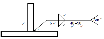 (8)
(8)
5.3 Dimensions of the material:
5.3.1 MeanØ = Inside Ø + Thickness
= 215 ÷ 20
= 235 mm
Mean circumfrence = Fx MeanØ
= Fx 235
= 738.27 mm
Round off to 740 mm (6)
5.3.2 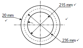 (4)
(4)
[23]
QUESTION 6: TOOLS AND EQUIPMENT (SPECIFIC)
6.1Punch and shear machine:
- Croppers are activated by hand or by foot. ✓
- A shear and punch machine is a heavy-duty machine for cutting steel profiles and punching holes into steel plates. ✓
- Croppers are electrically / hydraulically driven engaging various shearing blades to shear / punch different profiles. ✓
- Punches and corresponding dies need to be set to the desired size before punching. ✓
- They do not require cooling fluid because the shearing action does not develop a great deal of heat. ✓(5)
6.2 Plasma cutter:
- The basic cutting process involves creating an electrical channel of ionised gas; that is plasma, ✓from the plasma cutter itself through the work piece that is being cut. Thus forming a completed electric circuit back to the plasma cutter via a grounding clamp. ✓
- This is accomplished by compressed air that is blown toward the work piece through a focused nozzle at high speed. ✓
- A high frequency, electrical arc is then formed within the gas between an electrode near or integrated into the gas nozzle and the work piece itself. ✓ (4)
6.3 Internal Thread cutting process:
- Drill the required core / root / inside diameter. ✓
- Use the three taps in order. ✓
- Check thread with gauge / bolt when complete. ✓ (3)
6.4 Brinell hardness test:
- The Brinell hardness tester makes use of a steel ball as indenter. ✓
- A load is applied to the test piece. ✓
- The diameter of the indentation is measured with a microscope. ✓
- The diameter is used to determine the Brinell reading. ✓ (4)
6.5 Rockwell hardness testing over Brinell hardness testing:
- The advantages of the Rockwell Hardness method include the direct readout of the Rockwell Hardness number. ✓✓
- Rapid testing time. ✓✓
(Any 1 x 2) (2)
[18]
QUESTION 7: FORCES (SPECIFIC)
7.1 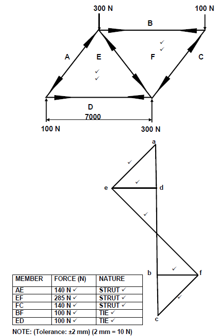 (19)
(19)
7.2 Beams:
7.2.1 Reactions at the supports RL and RR:
RL x 12 = (3 x 3) + (5 + 6) + (4 x 9)
RL = 6.25N
RR x 12 = (4 x 3) + (5 x 6) + (3 x 9)
RR = 5.75N (4)
7.2.2 Bending moments:
BMB = (6.25 x 3)
= 18.75 N.m
BMC = (6.25 x 6) - (4 x 3)
= 25.5 N.m
BMD = (6.25 x 9) - (4 x 6) - (5 x 3)
= 17.25 N.m (6)
7.2.3 Bending moments diagram: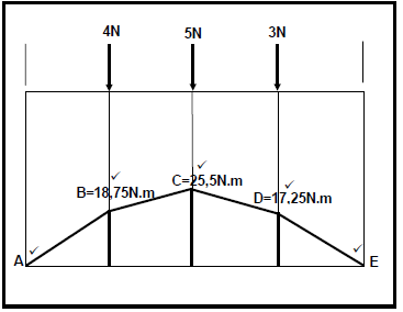 (5)
(5)
SCALES: Space diagram:10 mm = 1 m
Bending moment diagram:5 mm = 1 N.m
7.3 Stress and Strain:
7.3.1 Stress in the shaft:
Area = DF2
4
= F x (32 x 10-3)2
4
= 0.8 x 10⁻³m2
σ = Load
Area
= 100 x 103
0.8 x 10-3
= 125 x 106Pa or 125MPa (5)
7.3.2 Strain in the steel:
ε= ΔL
oL
= 0.5
120
=4.17 x 10⁻³ (3)
7.3.3 Young’s modulus of elasticity:
E = σ
ε
= 125 x 10 6
4.17 x 10-3
= 29.98 x 10⁹ Pa or 29.98GPa (3)
[45]
QUESTION 8: JOINING METHODS (WELD INSPECTION) (SPECIFIC)
8.1 Factors to be observed during oxy-acetylene welding:
- Correct flame for the work at hand. ✓
- Correct angle of welding torch and rod. ✓
- Depth of fusion. ✓
- The welding rate. ✓
(Any 2 x 1) (2)
8.2 Welding defects:
Incomplete penetration:
- Welding current too low.✓
- Welding speed too fast. ✓
- Incorrect welding angle. ✓
- Poor joint preparation. ✓
- Insufficient root gap. ✓
- Wrong polarity. ✓
- Arc length too short. ✓
- Wrong electrode used. ✓
(Any 2 x 1) (2)
8.3 Methods reducing of welding defects:
8.3.1 Slag inclusion:
- Using well-maintained consumables. ✓
- Ensure adequate shielding gas. ✓
- Clean the joint properly.✓
- Slag must be removed before welding the next bead.✓
- Too slow welding movements. ✓
- Electrode too big. ✓
- Wrong or too big weaving action. ✓
(Any 2 x 1) (2)
8.3.2 Centreline cracks:
- Aiming for a width-to-depth ratio of 1:1. ✓
- Decreasing the current to reduce excess penetration. ✓
- Decreasing welding voltage / current. ✓
- Slowing travel speed. ✓
- Reduce high carbon content in weld. ✓
- Welding while joint is under stress due to joint design, use clamping devices. ✓
(Any 2 x 1) (2)
8.4 Porosity:
Porosity refers to cavity-type pores ✓ (bubbles or gas pockets) formed by gas✓ during the solidification ✓ of molten weld metal. (3)
8.5 Non-destructive test:
The welded joint is not ✓destroyed ✓ in the process of testing. (2)
8.6 Ultrasonic test:
- To detect internal flaws. ✓
- To detect surface flaws. ✓ (2)
8.7 Visual inspection:
- Shape of profile. ✓
- Uniformity of surface. ✓
- Overlap. ✓
- Undercutting. ✓
- Penetration bead. ✓
- Root groove. ✓
(Any 3 x 1) (3)
8.8 Nick break test:
- Make a hacksaw cut at both edges, through the centre of the weld. ✓
- Place specimen on two steel supports.✓
- Use a sledge hammer to break the specimen in the area of the cuts.✓
- Inspect the exposed weld metal in the break for incomplete fusion, slag inclusion, etc. ✓ (5)
[23]
QUESTION 9: JOINING METHODS (STRESSES AND DISTORTION) (SPECIFIC)
9.1 Shrinkage in welding:
Shrinkage is a form of plastic deformation ✓ where the metal has deformed as a result ✓ of contraction ✓ on cooling. ✓ (4)
9.2 Factors affecting distortion and residual stress:
- If the expansion that occurs when metal is heated is resisted, then deformation will occur. ✓
- When contraction that occurs on cooling is resisted, then a stress will be applied. ✓
- If that applied stress causes movement, then distortion occurs. ✓
- If the applied stress does not cause movement, then there will be residual stress in the welded joint. ✓ (4)
9.3 Back-step welding: 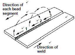 (6)
(6)
9.4 Factors affecting the temperature of cold worked steel for re-crystallisation:
- The prior amount of cold work.✓
- The temperature and time of annealing process. ✓
- Composition of the metal. ✓
- The melting point. ✓ (4)
[18]
QUESTION 10: MAINTENANCE (SPECIFIC)
10.1 Effect of overloading:
10.1.1 Power saw:
- Driving motor will be damaged. ✓
- Excessive strain on the driving system. ✓
- The cutting blade will be damaged. ✓
- The blade may deflect and result in a skew cut. ✓
(Any 1 x 1) (1)
10.1.2 Bench grinder:
- Result in malfunction due to excessive loads on the spindle bearings, grinding wheel and machine motor. ✓
- Overloading will wear the grinding wheel excessively and unevenly. ✓
- It shortens the life span of the spindle bearings and motor. ✓
(Any 1 x 1) (1)
10.2 Effect of friction:
10.2.1 Drill bit of a pedestal drill:
- Due to the heat caused by friction the cutting edge of the drill bit softens / blunt.✓
- Lifespan of the drill bit will be reduced. ✓
(Any 1 x 1) (1)
10.2.2 Rolling machine’s bearings:
Journals and bearings will prematurely wear out. ✓(1)
10.3 A punch and a shearing machine:
- Check the condition of the switch gear, wiring and isolation. ✓
- Ensure that the isolator is lockable. ✓
- Check the condition of the stop / start equipment. ✓
- Check the operation of emergency stop where fitted. ✓
- Check connections of electrical wiring. ✓
(Any 2 x 1) (2)
10.4 Record keeping:
- Monitoring of the machine’s condition✓
- Monitoring of the maintenance costs on the machines. ✓
- Upholding the warranties and guarantees. ✓
(Any 2 x 1) (2)
[8]
QUESTION 11: TERMINOLOGY (DEVELOPMENT) (SPECIFIC)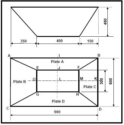
11.1.1 Length of IJ:
Plates A and D.
IJ = IL - JL
IJ = 300 - 150
IJ = 150mm (3)
11.1.2 True length of AE:
True Length AE = √IE2 + AI2 + VH2
AE = √1502 + 3502 + 4502
AE = 589.49mm
= 590mm (6)
11.1.3 Length of MK:
MK = LK - LM
MK = 350 - 200
MK = 150mm (2)
11.1.4 The True length of DH:
True length of DH = √HK2 + KD2 + VH2
DH = √1502 + 1502 + 4502
DH = 497.49mm
SAY 498 mm(6)
11.1.5 Pattern for plates A: (2)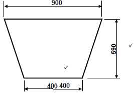
11.1.6 Pattern for Plate C: (2)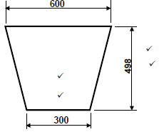
[21]
TOTAL: 200