CIVIL TECHNOLOGY: CIVIL SERVICES GRADE 12 QUESTIONS - NSC PAST PAPERS AND MEMOS MAY/JUNE 2019
Share via Whatsapp Join our WhatsApp Group Join our Telegram GroupCIVIL TECHNOLOGY: CIVIL SERVICES
GRADE 12
NATIONAL SENIOR CERTIFICATE EXAMINATIONS
MAY/JUNE2019
REQUIREMENTS:
- Drawing instruments
- A non-programmable calculator
- ANSWER BOOK
INSTRUCTIONS AND INFORMATION
- This question paper consists of SIX questions.
- Answer ALL the questions.
- Answer each question as a whole. Do NOT separate subsections of questions.
- Start the answer to EACH question on a NEW page.
- Do NOT write in the margins of the ANSWER BOOK.
- You may use sketches to illustrate your answers.
- Write ALL calculations and answers in the ANSWER BOOK or on the attached ANSWER SHEETS.
- Use the mark allocation as a guide to the length of your answers.
- Make drawings and sketches in pencil, fully dimensioned and neatly finished off with descriptive titles and notes to conform to the SANS/SABS Code of Practice for Building Drawings.
- For the purpose of this question paper, the size of a brick should be taken as 220 mm x 110 mm x 75 mm.
- Use your own discretion where dimensions and/or details have been omitted.
- Answer QUESTIONS 2, 3.3, 3.4, 3.5, 4.2, 5.6, 6.2, 6.5 and 6.6 on the attached ANSWER SHEETS using drawing instruments where necessary.
- Write your CENTRE NUMBER and EXAMINATION NUMBER on every ANSWER SHEET and hand them in with your ANSWER BOOK, whether you have used them or not.
- Drawings in the question paper are NOT to scale due to electronic transfer.
- Google Images was used as the source for all photographs and pictures.
QUESTION 1: OHSA, SAFETY, MATERIALS, TOOLS, EQUIPMENT AND JOINING (GENERIC)
Start this question on a NEW page.
1.1 Choose a description from COLUMN B that matches an item in COLUMN A. Write only the letter (A–G) next to the question numbers (1.1.1 to 1.1.5) in the ANSWER BOOK, e.g. 1.1.6 H.
| COLUMN A | COLUMN B |
| 1.1.1 Galvanising 1.1.2 Electroplating 1.1.3 Curing 1.1.4 Paint 1.1.5 Powder coating |
|
(5 x 1) (5)
1.2 Explain ONE cause of injuries when handling materials. (1)
1.3 Give the angle/ratio at which a ladder should be placed against a wall. (2)
1.4 Explain TWO safety precautions that must be followed when using a builder's hoist. (2)
1.5 FIGURE 1.5 below shows tools that are used on a construction site.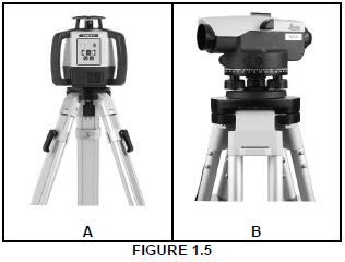
1.5.1 Identify both A and B. (2)
1.5.2 Name ONE use of A and B respectively. (2)
1.6 The pictures below illustrate the steps followed when fixing material to a floor with a fastener.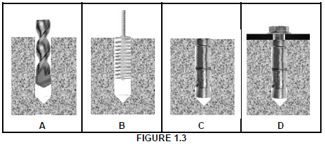
1.6.1 Identify the fastener that is used in D. (1)
1.6.2 Describe the steps in A–D above in your ANSWER BOOK. (4)
1.6.3 Justify the use of this fastener to secure the bracket of a heavy gate to a wall. (1)
[20]
QUESTION 2: GRAPHICS AS MEANS OF COMMUNICATION (GENERIC)
Start this question on a NEW page.
FIGURE 2 on the next page shows an elevation and a ground floor plan that appear on a building plan. Analyse the drawings and complete the table on ANSWER SHEET 2.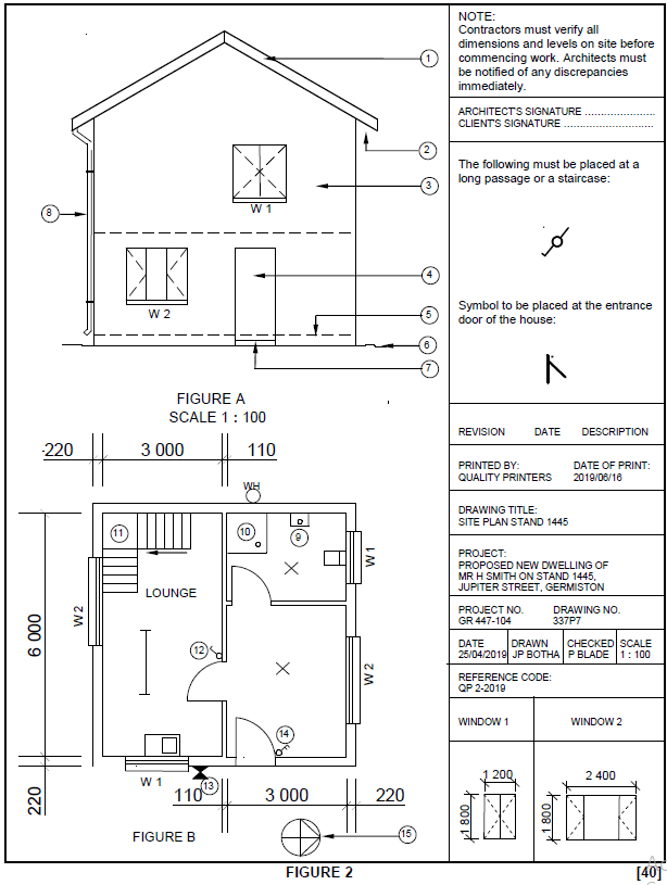
QUESTION 3: CONSTRUCTION ASSOCIATED WITH CIVIL SERVICES, OHSA, AND QUANTITIES (SPECIFIC)
Start this question on a NEW page.
3.1 FIGURE 3.1 below is an illustration of a manhole. Study the illustration and answer the questions that follow.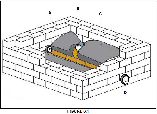
3.1.1 Describe the difference between A and D with regard to the flow of sewage. (2)
3.1.2 Identify B. (1)
3.1.3 The benching (C) must be installed at a slope. Give ONE reason for this. (1)
3.1.4 Recommend ONE type of brick that can be used to build the walls of the manhole. (1)
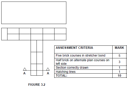
3.2 FIGURE 3.2 on ANSWER SHEET 3.2 shows the top view of a T-junction and the incomplete sectional view of a one-brick wall in stretcher bond.
Draw the sectional front view by projecting it from the given top view. Show FIVE brick courses. (10)
3.3 FIGURE 3.3 below is a drawing of a type of shore used in trenches. Study the drawing and answer the questions that follow.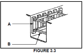
3.3.1 Name the type of soil where this type of shore will be used. (1)
3.3.2 Identify A and B. (2)
3.4 A mask will not provide sufficient protection when you are working inside a manhole. Name the safety equipment that will be appropriate. (1)
3.5 Describe THREE regulations that must be adhered to when workers work in high places. (3)
3.6 FIGURE 3.6 below is a drawing of the incomplete sectional view through the bricks and concrete floor of a septic tank. Use ANSWER SHEET 3.6 and answer the questions that follow. Round off your answer to TWO decimal places.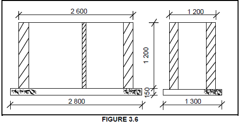
Specifications:
- External walls are 220 mm wide.
- Partition wall is 110 mm wide.
- Use 50 bricks per square metre for a half-brick wall.
Calculate the number of bricks needed for the partition wall, excluding breakage. Ignore the openings. (8)
[30]
QUESTION 4: HOT- AND COLD-WATER SUPPLY, TOOLS, EQUIPMENT AND MATERIALS (SPECIFIC)
Start this question on a NEW page.
4.1 FIGURE 4.1 below shows a picture of a water-heating system that is used in the hot-water system of a house.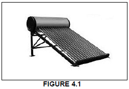
4.1.1 Identify the water-heating system in FIGURE 4.1. (1)
4.1.2 Name the source that is used to heat the water in the system indicated in FIGURE 4.1. (1)
4.1.3 Describe TWO disadvantages of using a heat pump in a hot-water system. (2)
4.2 There are many different faults that can occur in hot-water systems. Explain ONE method of preventing the following situations:
4.2.1 Poor hot-water pressure (1)
4.2.2 Water that is not hot enough (1)
4.2.3 Dripping geyser overflow (1)
4.3 Draw the SANS-approved symbols for the following parts found in a hot-water system:
4.3.1 Pressure-control valve (adjustable) (2)
4.3.2 Pressure-relief valve (2)
4.3.3 Shower (fixed) (2)
4.4 FIGURE 4.4 below shows a picture of a valve used in the cold-water supply of a house. Study the picture and answer the questions that follow.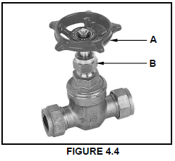
4.4.1 Identify the valve in FIGURE 4.4. (1)
4.4.2 Identify parts A and B in FIGURE 4.4. (2)
4.4.3 Recommend ONE place where the valve in FIGURE 4.4 can be used. (1)
4.5 Name TWO water-saving devices that can help reduce water consumption in our homes. (2)
4.6 Explain in FIVE steps how you would repair a damaged galvanised pipe that is installed above ground level by using a Johnson pipe coupling. (5)
4.7 Choose a description from COLUMN B that matches an item in COLUMN A.
Write only the letter (A–F) next to the question numbers (4.7.1 to 4.7.5) in the ANSWER BOOK, e.g. 4.7.6 G. (5 x 1) (5)
| COLUMN A | COLUMN B |
4.7.1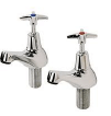 | A. alternative heating unit that saves electricity |
4.7.2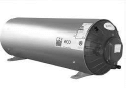 | B. high-pressure geyser |
4.7.3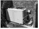 | C. bibcock (tap) |
4.7.4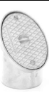 | D. inspection eye |
4.7.5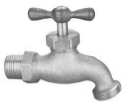 | E. pillar tap |
| F. rodding eye |
4.8 Explain TWO problems that can be caused by dezincification. (2)
4.9 Describe TWO methods used to prevent galvanic corrosion from occurring in metals. (2)
4.10 FIGURE 4.10 below shows a picture of a machine. Study the picture and answer the questions that follow.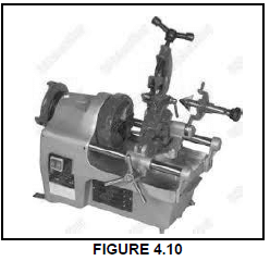
4.10.1 Identify the machine in FIGURE 4.10. (1)
4.10.2 State ONE use of the machine in FIGURE 4.10. (1)
4.10.3 Explain TWO factors to consider when taking care of this machine. (2)
4.11 Describe the use of a water-pressure testing pump. (1)
4.12 Explain TWO factors to consider when taking care of a water-pressure testing pump. (2)
[40]
QUESTION 5: GRAPHICS AS MEANS OF COMMUNICATION, ROOF WORK AND STORM WATER (SPECIFIC)
Start this question on a NEW page.
5.1 Give ONE word/term for each of the following descriptions by choosing a word/term from the list below. Write only the word/term next to the question numbers (5.1.1 to 5.1.5) in the ANSWER BOOK, e.g. 5.1.6 drainage system.
fascia board; rip saw; gutter seal; steel clip; flashing;
hacksaw; stop end; gutter; union clip; barge board
5.1.1 The fitting used to prevent rain water from flowing off the gutter (1)
5.1.2 The material used to waterproof roofs (1)
5.1.3 The tool used to cut PVC guttering to size (1)
5.1.4 The object used to clip together PVC gutters (1)
5.1.5 A gutter can be mounted to this feature of the roof (1)
5.2 FIGURE 5.2 below is a drawing of a part of a roof. Study the drawing and answer the questions that follow.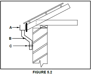
5.2.1 Identify A. (1)
5.2.2 Name B, which indicates an important part of the downpipe. (1)
5.2.3 Describe the function of C. (1)
5.3 FIGURE 5.3 below shows a metal object used to channel storm water to catchment areas.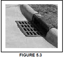
5.3.1 Name the metal object shown in FIGURE 5.3. (1)
5.3.2 Recommend TWO other methods that can be used to channel storm water to catchment areas. (2)
5.3.3 Storm-water construction should be managed by qualified people because if it is constructed or managed poorly, it may have negative consequences. Explain ONE consequence if storm-water systems are constructed and managed poorly. (1)
5.4 ANSWER SHEET 5.4 shows a drawing of a frustrum of a cone where the base of the cone is not parallel to the horizontal axis. Use the drawing and information on ANSWER SHEET 5.4 and draw the development of the cone. Show ALL construction lines. Do NOT redraw the drawing, but project the development from the given drawing. (18)
[30]
QUESTION 6: SEWERAGE, SANITARY FITTINGS AND JOINING (SPECIFIC)
Start this question on a NEW page.
6.1 Various options are given as possible answers to the following questions. Choose the answer and write only the letter (A–D) next to the question numbers (6.1.1 to 6.1.5) in the ANSWER BOOK, e.g. 6.1.6 C.
6.1.1 Sewage is water that contains … contaminants.
- green
- organic
- poisonous
- soapy (1)
6.1.2 A soil vent pipe runs … from the underground sewerage and allows odours and gases to escape.
- vertically
- horizontally
- diagonally
- All the above-mentioned (1)
6.1.3 Sewer pipes should be at least … in diameter.
- 50 mm
- 150 mm
- 100 mm
- 80 mm (1)
6.1.4 Water from sinks, baths and basins is discharged into ...
- waste-water pipes.
- soil pipes.
- soil vent pipes.
- All the above-mentioned (1)
6.1.5 A … can be used to join straight lengths of pipes.
- soil pipe
- stop end
- straight coupling
- None of the above-mentioned (1)
6.2 FIGURE 6.2 below shows drawings of TWO different water traps found in a sewerage system.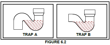
6.2.1 Differentiate between A and B by referring to the shape of the traps. (2)
6.2.2 Explain the function of the water at the base of EACH of the fittings in FIGURE 6.2. (1)
6.3 FIGURE 6.3 below is a drawing of the sectional view through a part of a building showing the installation of a water closet. Study the drawing and answer the questions that follow.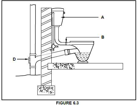
6.3.1 Identify part A. (1)
6.3.2 Explain why cone B is made out of rubber. (1)
6.3.3 Identify D and explain ONE consequence of not having this fitting. (2)
6.3.4 Name ONE tool that you will use to clear a blocked waste pipe that is connected to a basin. (1)
6.3.5 A ball valve is found inside part A in FIGURE 6.3 and regulates the water level. In you ANSWER BOOK, draw a neat line diagram of a ball valve as seen from the direction of A in FIGURE 6.3. Show the following in your drawing:
- Ball
- Lever arm
- Casing with silencing tube
- Label any TWO parts of the drawing. (5)
6.4 FIGURE 6.4 on ANSWER SHEET 6.4 is a drawing of a part of a building with sanitary fitments and sewerage components. Use ANSWER SHEET 6.4 and develop and draw a one-pipe sewerage layout for this building up to the indicated manhole. ALL regulations and design principles of a good drainage (sewerage) system must be considered and appropriate symbols and abbreviations must be used.
The drainage system should consist of:
- 2 x rodding eyes
- 5 x inspection eyes
- 1 x ventilation pipe
- Main sewerage pipes
- Branch pipes (10)
6.5 FIGURE 6.5 below shows a cross section of a part of a sewerage system. Study the drawing and answer the questions that follow.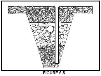
6.5.1 Identify the part of the sewerage system in FIGURE 6.5. (1)
6.5.2 Predict ONE consequence of channelling grey water into a septic tank. (1)
6.6 Name ONE situation where you would install a vacuum tank. (1)
6.7 Identify the fitting used in a sewerage system, illustrated in FIGURE 6.7 below. (1)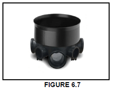
6.8 Name TWO methods that can be used to join copper pipes. (2)
6.9 Draw a neat line diagram in your ANSWER BOOK to show how two pieces of sheet metal interlocks when you make a grooved seam lap joint. (2)
6.10 FIGURE 6.10 below is a drawing of a soldered joint and the forces that act upon it.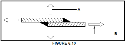
6.10.1 Identify forces A and B in FIGURE 6.10. (2)
6.10.2 Give TWO reasons why the contact of a soldering iron on the sheet metal is important while soldering overlap joints. (2)
[40]
TOTAL: 200
ANSWER SHEET 2
| NO | QUESTIONS | ANSWERS | MARKS |
| 1 | Identify the elevation shown in FIGURE A | 1 | |
| 2 | Name the scale of FIGURE B. | 1 | |
| 3 | Identify number 1. | 1 | |
| 4 | Identify number 2. | 1 | |
| 5 | Recommend a suitable finish for number 3. | 1 | |
| 6 | What is indicated by number 4? | 1 | |
| 7 | Identify the drawing symbol indicated by number 5 | 1 | |
| 8 | Identify the drawing symbol indicated by number 6 | 1 | |
| 9 | What is indicated by number 7? | 1 | |
| 10 | Give the date on which the building plan was printed | 1 | |
| 11 | Who checked the building plan? | 1 | |
| 12 | Name the electrical drawing symbol in the column for the notes in FIGURE 2 that must be placed at a staircase. | 1 | |
| 13 | Name the electrical feature in the column for the notes in FIGURE 2 that must be placed at the entrance door of the house. | 1 | |
| 14 | Identify the type of roof that is used on the building in FIGURE A. | 1 | |
| 15 | Explain the purpose of number 1. | 1 | |
| 16 | Who is the owner of this house? | 1 | |
| 17 | In which street is the proposed dwelling situated? | 1 | |
| 18 | Identify number 8. | 1 | |
| 19 | What is the sanitary fitting indicated by number 9 used for? | 1 | |
| 20 | Recommend an alternative sanitary fitting to replace number 10 that will serve a similar purpose. | 1 | |
| 21 | Explain the purpose of number 11 as indicated on the staircase. | 1 | |
| 22 | What is indicated by number 13? | 1 | |
| 23 | What is indicated by number 15? | 1 | |
| 24 | Deduce the height of window 1 from the window schedule. | 1 | |
| 25 | Deduce the width of window 2 from the window schedule. | 1 | |
| 26 | Name the elevations of the building on which the staircase is situated. | 2 | |
| 27 | Differentiate between the electrical symbols indicated by numbers 12 and 14. | 2 | |
| 28 | Recommend a suitable floor covering for the lounge. | 1 | |
| 29 | Calculate the area of the lounge in m². Show ALL calculations. | 3 | |
| 30 | Calculate the perimeter of the building. Show ALL calculations. | 7 | |
| TOTAL: | 40 |
ANSWER SHEET 3.2
ANSWER SHEET 3.6
| A | B | C | D |
| Total length of partition wall | |||
| 1/ mm - 2/ | |||
| = mm ✓ (2) | |||
| Area of partition wall | |||
| 1/ | |||
| (3) | |||
| Number of bricks needed for partition wall excluding 5% for breakage | |||
| 1/ | |||
| Bricks are needed(3) |
ANSWER SHEET 5.4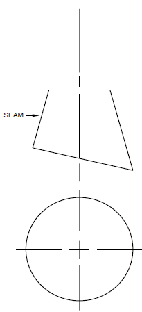
| ASSESSMENT CRITERIA | M |
| Construction lines to top of cone | 2 |
| Construction lines of outer circle | 2 |
| Divide outer circle in 12 parts | 1 |
| Construction lines from top of cone to outer circle | 3 |
| Cone measurement (marked/transferred) from front view to determine top part of development (ONE mark for every FOUR coordinates = 3) | 6 |
| Outside lines of development | 2 |
| 3 mm seam on both sides | 2 |
| TOTAL: | 18 |
ANSWER SHEET 6.4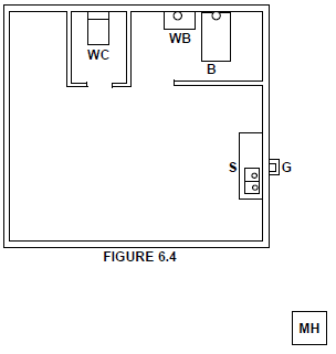
| ASSESSMENT CRITERIA | MARK |
| 2 x rodding eyes correctly positioned | 2 |
| 5 x inspection eyes correctly positioned | 5 |
| 1 x ventilation pipe correctly positioned | 1 |
| Sewerage pipes drawn correctly (main and branch pipes) | 2 |
| TOTAL: | 10 |