CIVIL TECHNOLOGY: WOOD WORKING GRADE 12 QUESTIONS - NSC PAST PAPERS AND MEMOS MAY/JUNE 2019
Share via Whatsapp Join our WhatsApp Group Join our Telegram GroupCIVIL TECHNOLOGY: WOODWORKING
GRADE 12
NATIONAL SENIOR CERTIFICATE EXAMINATIONS
MAY/JUNE 2019
REQUIREMENTS:
- Drawing instruments
- A non-programmable calculator
- ANSWER BOOK
INSTRUCTIONS AND INFORMATION
- This question paper consists of SIX questions.
- Answer ALL the questions.
- Answer each question as a whole. Do NOT separate subsections of questions.
- Start the answer to EACH question on a NEW page.
- Do NOT write in the margins of the ANSWER BOOK.
- You may use sketches to illustrate your answers.
- Write ALL calculations and answers in the ANSWER BOOK or on the attached ANSWER SHEETS.
- Use the mark allocation as a guide to the length of your answers.
- Make drawings and sketches in pencil, fully dimensioned and neatly finished off with descriptive titles and notes to conform to the SANS/SABS Code of Practice for Building Drawings.
- For the purpose of this question paper, the size of a brick should be taken as 220 mm x 110 mm x 75 mm.
- Use your own discretion where dimensions and/or details have been omitted.
- Answer QUESTIONS 2, 3.3, 3.4, 3.5, 4.2, 5.6, 6.2, 6.5 and 6.6 on the attached ANSWER SHEETS using drawing instruments where necessary.
- Write your CENTRE NUMBER and EXAMINATION NUMBER on every ANSWER SHEET and hand them in with your ANSWER BOOK, whether you have used them or not.
- Drawings in the question paper are NOT to scale due to electronic transfer.
- Google Images was used as the source for all photographs and pictures.
QUESTION 1: OHSA, SAFETY, MATERIALS, TOOLS, EQUIPMENT AND JOINING (GENERIC)
Start this question on a NEW page.
1.1 Choose a description from COLUMN B that matches an item in COLUMN A. Write only the letter (A–G) next to the question numbers (1.1.1 to 1.1.5) in the ANSWER BOOK, e.g. 1.1.6 H.
| COLUMN A | COLUMN B |
| 1.1.1 Galvanising 1.1.2 Electroplating 1.1.3 Curing 1.1.4 Paint 1.1.5 Powder coating |
|
(5 x 1) (5)
1.2 Explain ONE cause of injuries when handling materials. (1)
1.3 Give the angle/ratio at which a ladder should be placed against a wall. (2)
1.4 Explain TWO safety precautions that must be followed when using a builder's hoist. (2)
1.5 FIGURE 1.5 below shows tools that are used on a construction site.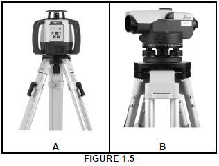
1.5.1 Identify both A and B. (2)
1.5.2 Name ONE use of A and B respectively. (2)
1.6 The pictures below illustrate the steps followed when fixing material to a floor with a fastener.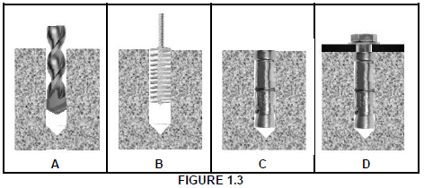
1.6.1 Identify the fastener that is used in D. (1)
1.6.2 Describe the steps in A–D above in your ANSWER BOOK. (4)
1.6.3 Justify the use of this fastener to secure the bracket of a heavy gate to a wall. (1)
[20]
QUESTION 2: GRAPHICS AS MEANS OF COMMUNICATION (GENERIC)
Start this question on a NEW page.
FIGURE 2 on the next page shows an elevation and a ground floor plan that appear on a building plan. Analyse the drawings and complete the table on ANSWER SHEET 2.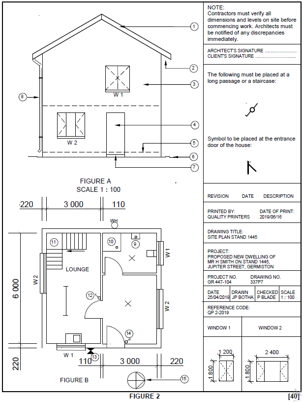
QUESTION 3: CASEMENTS, CUPBOARDS, WALL-PANELLING AND QUANTITIES (SPECIFIC)
Start this question on a NEW page.
3.1 Name the part of a casement that separates two window panes so that they do not touch each other. (1)
3.2 FIGURE 3.2 below shows an external elevation of a double casement with fanlights. Name parts A–E. (5)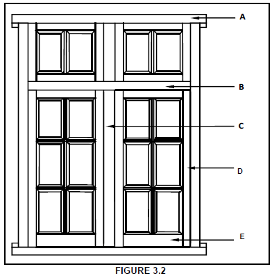
3.3 FIGURE 3.3 below shows the front view of a built-in cupboard without the doors. Use ANSWER SHEET 3.3 and draw a vertical sectional view of the cupboard to scale 1 : 10.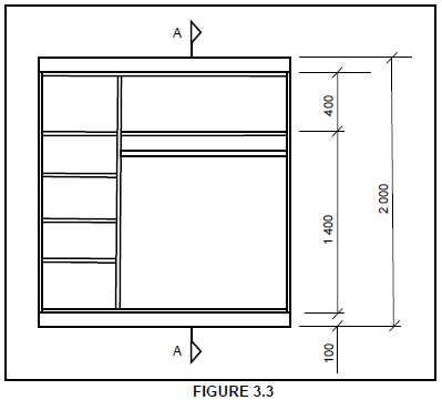
Use the following specifications:
- All shelves and sides are 16 mm thick.
- The back is 3 mm thick.
- The depth of the cupboard is 570 mm.
- Show hanging rail in sectional view. (11)
3.4 Use ANSWER SHEET 3.4 and draw, to scale 1 : 5, a vertical sectional view through the bottom part of a tongue and groove wall panel. The wall and floor level are given.
Show the following parts clearly:
- Horizontal rough grounds: 25 mm x 50 mm
- Tongue and groove board: 15 mm thick
- Skirting: 22 mm thick
- Quadrant moulding: 22 mm thick (6)
3.5 FIGURE 3.5 below shows the floor plan of a building with a gable roof. The centre-to-centre distance between the roof trusses is 1 300 mm. Study the figure and use ANSWER SHEET 3.5 to answer the questions that follow.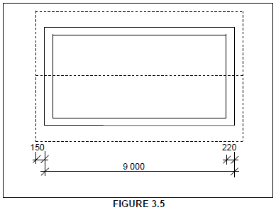
3.5.1 Calculate the length, in metres, of fascia board needed for the whole roof.(2)
3.5.2 Calculate the number of trusses needed for the roof.(5)
[30]
QUESTION 4: ROOFS, CEILINGS, TOOLS AND EQUIPMENT, AND MATERIALS (SPECIFIC)
Start this question on a NEW page.
4.1 Choose a term from COLUMN B that matches a roof in COLUMN A. Write only the letter (A–G) next to the question numbers (4.1.1 to 4.1.5) in the ANSWER BOOK, e.g. 4.1.6 H.
| COLUMN A | COLUMN B |
4.1.1  | A. lean-to roof |
4.1.2 | B. couple roof |
4.1.3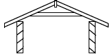 | C. king post roof |
4.1.4 | D. collar-tie roof |
4.1.5 | E. South African (Howe) roof |
| F. close-coupled roof | |
| G. thatch roof |
(5 x 1) (5)
4.2 Use ANSWER SHEET 4.2 and complete the vertical section through the foot of a roof truss by drawing the closed eaves to scale 1 : 10.
Show the following on your drawing:
- Fascia board: 230 mm x 38 mm
- Hanger: 38 mm x 38 mm
- Bearer: 38 mm x 38 mm
- 6 mm fibre-cement board
- Two quarter-round mouldings below the fibre-cement board (7)
4.3 Differentiate between a hipped roof and a gable roof in terms of the quantity of material and the type of construction used. Tabulate your answer. (4)
4.4 Name THREE different methods of joining roof truss members to each other. (3)
4.5 Name TWO components that can be used to keep a trap door of a ceiling in position. (2)
4.6 Give the minimum measurements for the opening of a trap door. (1)
4.7 FIGURE 4.7 below shows a portable electrical machine. Study the picture and answer the questions that follow.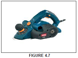
4.7.1 Identify the machine.(1)
4.7.2 Name TWO personal safety equipment that you must be wearing when operating this machine.(2)
4.7.3 Explain how you will store the machine.(2)
4.7.4 Explain TWO precautions that should be applied to a piece of timber to prevent damages to the machine shown in FIGURE 4.7. (2)
4.8 FIGURE 4.8 shows a radial arm saw. Study the picture and answer the questions that follow.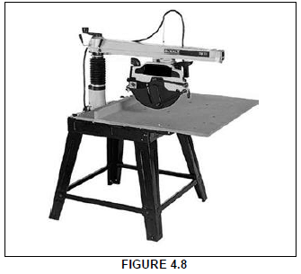
4.8.1 Describe THREE precautions that should be taken to ensure the safe handling of the machine.(3)
4.8.2 Explain how the blade of the machine must be cared for to prevent it from being damaged.(2)
4.9 Explain in FIVE steps how you will apply two layers of sanding sealer to a door that has been sanded smooth. (5)
4.10 Explain how you will recognise a graded timber plank/board. (1)
[40]
QUESTION 5: CENTRING, FORMWORK, SHORING AND GRAPHICS AS MEANS OF COMMUNICATION (SPECIFIC)
Start this question on a NEW page.
5.1 Draw a neat two-dimensional sketch to show the open laggings, rib and a bearer to support a segmental arch.
Show the following on your drawing:
- Bearer
- Rib
- Laggings
- Space between laggings
- Only half of the centre
- Any THREE labels (8)
5.2 Give ONE word/term for each of the following descriptions by choosing a word/term from the list below. Write only the word/term next to the question numbers (5.2.1 to 5.2.5) in the ANSWER BOOK, e.g. 5.2.6 Riser.
fish plate; ties; soleplate; folding wedges; props; clamps; braces/struts
5.2.1 Fixed diagonally to the struts/props and head tree to strengthen the formwork (1)
5.2.2 To fix the props and bearers together (1)
5.2.3 Fixed to the beam sides to make them stronger (1)
5.2.4 Placed under the props to allow the raising and lowering of the formwork to the required height (1)
5.2.5 Transfers the load of the concrete beam evenly to the ground (1)
5.3 Name TWO types of material that can be used for the lining on the inside of formwork. (2)
5.4 FIGURE 5.4 below shows the formwork for a square concrete column. Study the picture and label parts A, B and C.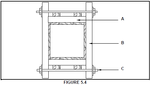 (3)
(3)
5.5 Draw a neat two-dimensional sketch, in good proportion, of the detail at the base of a dead shore.
Show the following on your drawing:
- Dead shore
- Folding wedges
- Soleplate
- Steel dog
- Any TWO labels (7)
5.6 Use ANSWER SHEET 5.6 and draw a neat two-dimensional sketch, in good proportion, of a lean-to roof.
Show the following on your drawing:
- Parapet wall
- Supporting wall
- Wall plate
- Rafter (5)
[30]
QUESTION 6: SUSPENDED FLOORS, STAIRCASES, IRONMONGERY, DOORS AND JOINING (SPECIFIC)
Start this question on a NEW page.
6.1 Various options are given as possible answers to the following questions. Choose the answer and write only the letter (A–D) next to the question numbers (6.1.1 to 6.1.5) in the ANSWER BOOK, e.g. 6.1.6 C.
6.1.1 Floorboards are attached to floor joists that are supported by ...
- struts that are resting on tie beams.
- props every 3 metres.
- bearers and brick piers on concrete bases.
- DPC. (1)
6.1.2 Ant guards are made from galvanised steel and placed ...
- underneath the wall plate.
- inside the air bricks.
- outside the house.
- on floor boards (1)
6.1.3 The width of a floor board should be at least 50 mm and not exceed ...
- 100 mm.
- 400 mm.
- 140 mm.
- 299 mm. (1)
6.1.4 Floor boards should have a ... joint.
- tongue and groove
- mortice and tenon
- haunched mortice and tenon
- rebate (1)
6.1.5 Staggered struts between the floor joist can be secured with …
- nails.
- screws.
- a truss hanger.
- All of the above-mentioned (1)
6.2 Use ANSWER SHEET 6.2 and draw, in good proportion, a sectional view of the external wall that supports a suspended timber floor. The foundation is given.
Show the following parts on your drawing:
- Foundation wall: 330 mm wide
- Wall of superstructure: 220 mm wide
- DPC
- Ant guard
- Air brick
- Wall plate
- Joist
- Any ONE label (9)
6.3 Explain a half-landing as used in a timber staircase. (3)
6.4 Explain the difference between a mortice lock and a night latch with regard to their placement and function. (4)
6.6 FIGURE 6.6 on ANSWER SHEET 6.6 shows the incomplete front view of a double tenon. Use ANSWER SHEET 6.6 and complete the drawing of the double tenon.
Show the following on your drawing:
- Grooves for the panels on both sides
- Double tenon
- Any TWO labels (7)
6.7 FIGURE 6.7 below shows a fastener used to join materials. Identify the fastener.
(1)
6.5 FIGURE 6.5 on ANSWER SHEET 6.5 shows an external view of an external door.
Use ANSWER SHEET 6.5 and complete the following:
- Print any FOUR labels on the drawing.
- Indicate the dimension of the height of the door.
- Indicate the dimension of the width of the door.
- Print the title of the drawing. (7)
6.8 Name ONE fastener to join the following:
6.8.1 Ceiling boards to brandering (1)
6.8.2 Roof tiles to battens (1)
6.8.3 Roof sheeting to purlins (1)
6.9 State ONE method of fixing a window pane to a frame. (1)
[40]
TOTAL: 200
ANSWER SHEET 2
| NO | QUESTIONS | ANSWERS | MARKS |
| 1 | Identify the elevation shown in FIGURE A | 1 | |
| 2 | Name the scale of FIGURE B. | 1 | |
| 3 | Identify number 1. | 1 | |
| 4 | Identify number 2. | 1 | |
| 5 | Recommend a suitable finish for number 3. | 1 | |
| 6 | What is indicated by number 4? | 1 | |
| 7 | Identify the drawing symbol indicated by number 5 | 1 | |
| 8 | Identify the drawing symbol indicated by number 6 | 1 | |
| 9 | What is indicated by number 7? | 1 | |
| 10 | Give the date on which the building plan was printed | 1 | |
| 11 | Who checked the building plan? | 1 | |
| 12 | Name the electrical drawing symbol in the column for the notes in FIGURE 2 that must be placed at a staircase. | 1 | |
| 13 | Name the electrical feature in the column for the notes in FIGURE 2 that must be placed at the entrance door of the house. | 1 | |
| 14 | Identify the type of roof that is used on the building in FIGURE A. | 1 | |
| 15 | Explain the purpose of number 1. | 1 | |
| 16 | Who is the owner of this house? | 1 | |
| 17 | In which street is the proposed dwelling situated? | 1 | |
| 18 | Identify number 8. | 1 | |
| 19 | What is the sanitary fitting indicated by number 9 used for? | 1 | |
| 20 | Recommend an alternative sanitary fitting to replace number 10 that will serve a similar purpose. | 1 | |
| 21 | Explain the purpose of number 11 as indicated on the staircase. | 1 | |
| 22 | What is indicated by number 13? | 1 | |
| 23 | What is indicated by number 15? | 1 | |
| 24 | Deduce the height of window 1 from the window schedule. | 1 | |
| 25 | Deduce the width of window 2 from the window schedule. | 1 | |
| 26 | Name the elevations of the building on which the staircase is situated. | 2 | |
| 27 | Differentiate between the electrical symbols indicated by numbers 12 and 14. | 2 | |
| 28 | Recommend a suitable floor covering for the lounge. | 1 | |
| 29 | Calculate the area of the lounge in m². Show ALL calculations. | 3 | |
| 30 | Calculate the perimeter of the building. Show ALL calculations. | 7 | |
| TOTAL: | 40 |
ANSWER SHEET 3.3
USE A MASK TO MARK THE DRAWING
| ASSESSMENT CRITERIA | MARK | CM |
| Front rail | 1 | |
| Top shelf | 1 | |
| Middle shelf | 1 | |
| Bottom shelf | 1 | |
| Hanging rail | 1 | |
| Kick plate | 1 | |
| Back of base | 1 | |
| Back of cupboard | 1 | |
| Application of scale: Correct height Correct depth Correct thickness of material | 1 1 1 1 | |
| TOTAL: | 11 |
ANSWER SHEET 3.4
| ASSESSMENT CRITERIA | MARKS | CANDIDATE'S MARK |
| Horizontal rough grounds | 2 | |
| Tongue and groove board | 1 | |
| Skirting | 1 | |
| Quadrant mould | 1 | |
| Application of scale More than 3 wrong no marks | 1 | |
| TOTAL: | 6 |
ANSWER SHEET 3.4
| A | B | C | D | |
| 3.5.1 | Length of fascia board | |||
| = | ||||
| = _______mm | ||||
| = _______m | ||||
| 3.5.2 | Number of roof trusses needed | |||
| Internal dimension + 1 Distance between centres | ||||
| = ____________ + 1 | ||||
| =____________ | ||||
| =____________ |
ANSWER SHEET 4.2
| ASSESSMENT CRITERIA | MARK |
| Fascia board: 230 mm x 38 mm | 1 |
| Hanger: 38 mm x 38 mm | 1 |
| Bearer: 38 mm x 38 mm | 1 |
| 6 mm fibre-cement board on closed eaves | 1 |
| Quarter round mouldings below fibre-cement board | 2 |
| Application of scale More than 3 wrong no marks | 1 |
| TOTAL: | 7 |
(7)
ANSWER SHEET 5.6
| ASSESSMENT CRITERIA | MARK |
| Parapet wall | 1 |
| Wall | 1 |
| Wall plate | 1 |
| Rafter | 1 |
| Proportion | 1 |
| TOTAL: | 5 |
(5)
ANSWER SHEET 6.2
| ASSESSMENT CRITERIA | MARK |
| Foundation wall: 330 mm | 1 |
| Wall of superstructure | 1 |
| DPC | 1 |
| Ant guard | 1 |
| Air brick | 1 |
| Wall plate | 1 |
| Floor joist | 1 |
| Proportion | 1 |
| Any ONE label | 1 |
| TOTAL: | 9 |
(9)
ANSWER SHEET 6.5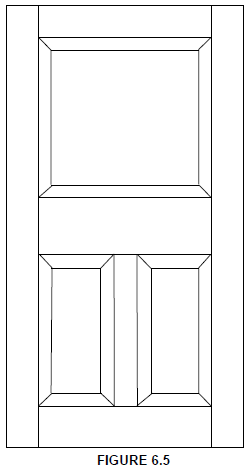
ANSWER SHEET 6.6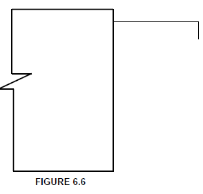
| ASSESSMENT CRITERIA | MARK |
| Hidden detail of grooves | 2 |
| Double tenon | 2 |
| TWO labels | 2 |
| Proportion of tenons | 1 |
| TOTAL: | 7 |