ELECTRICAL TECHNOLOGY:POWER SYSTEM GRADE 12 QUESTIONS - NSC PAST PAPERS AND MEMOS MAY/JUNE 2019
Share via Whatsapp Join our WhatsApp Group Join our Telegram GroupELECTRICAL TECHNOLOGY: POWER SYSTEMS
GRADE 12
NATIONAL SENIOR CERTIFICATE EXAMINATIONS
MAY/JUNE 2019
INSTRUCTIONS AND INFORMATION
- This question paper consists of SIX questions.
- Answer ALL the questions.
- Sketches and diagrams must be large, neat and fully labelled.
- Show ALL calculations and round off answers correctly to TWO decimal places.
- Number the answers correctly according to the numbering system used in this question paper.
- You may use a non-programmable calculator.
- Show the units for ALL answers of calculations.
- A formula sheet is attached at the end of this question paper.
- Write neatly and legibly.
QUESTION 1: OCCUPATIONAL HEALTH AND SAFETY (GENERIC)
1.1 Define the term accident with reference to the Occupational Health and Safety Act, 1993 (Act 85 of 1993). (3)
1.2 State TWO procedures to follow when evacuating a workshop in an emergency. (2)
1.3 Explain why you must protect yourself when helping a person who is being shocked by electricity. (1)
1.4 Briefly describe a third degree burn. (2)
1.5 Explain why a person should not interfere with, or misuse, equipment in the workshop that is provided for health or safety. (2)
[10]
QUESTION 2: RLC CIRCUITS (GENERIC)
2.1 Define the following terms:
2.1.1 Capacitive reactance (2)
2.1.2 Inductive reactance (2)
2.2 FIGURE 2.2 below represents an RLC series circuit that consists of a 25 Ω resistor, a 44 mH inductor and a 120 μF capacitor, all connected across a 120 V/60 Hz supply. Answer the questions that follow.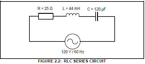
R = 25 Ω
L = 44 mH
C = 120 μF
VS = 120 V
f = 60 Hz
Calculate the:
2.2.1 Inductive reactance (3)
2.2.2 Capacitive reactance (3)
2.2.3 Impedance of the circuit (3)
2.3 FIGURE 2.3 below shows an RLC parallel circuit that consists of a 40 Ω resistor, an inductor with unknown inductance and a capacitor with a capacitive reactance of 60 Ω, all connected across a 220 V/60 Hz supply.
Answer the questions that follow.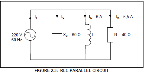
Given:
VS = 220 V L
F = 60 Hz
R = 40 Ω
XC = 60 Ω
IL = 6 A
IR = 5,5 A
2.3.1 Calculate the current through the capacitor. (3)
2.3.2 Calculate the reactive current. (3)
2.3.3 State, with a reason, whether the phase angle is leading or lagging. (2)
2.4 FIGURE 2.4 below shows an RLC series circuit that consists of a 12 Ω resistor, an inductor and a variable capacitor connected across a 120 V AC supply. The circuit resonates at 1 kHz. Answer the questions that follow.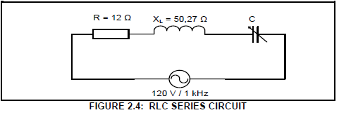
Given:
R = 12 Ω
XL = 50,27 Ω
VS = 120 V
fr = 1 kHz
2.4.1 State the value of the capacitive reactance at resonance. (1)
2.4.2 Calculate the value of the capacitor at resonance. (3)
2.4.3 Explain how the value of the current at resonance will be affected if the value of the resistance is doubled. (2)
2.5 A coil with a negligible resistance has an inductance of 80 mH and is connected in series with a 33 μF capacitor and a 30 Ω resistor. The circuit is then connected to a 120 V alternating supply with a variable frequency.
Given:
L = 80 mH
C = 33 μF
R = 30 Ω
VS = 120 V
Calculate the following:
2.5.1 Resonant frequency (3)
2.5.2 Current at resonance (3)
2.5.3 Voltage drop across the inductor at resonance if the inductive reactance is 49,24 Ω (3)
2.5.4 Explain why the voltage drop across the inductor at resonance is greater than the value of the supply voltage. (4)
[40]
QUESTION 3: THREE-PHASE AC GENERATION (SPECIFIC)
3.1 State the functions of the following meters:
3.1.1 Power-factor meter (1)
3.1.2 Kilowatt-hour meter (2)
3.2 Discuss the process of three-phase AC generation from the supplier to the consumer, in three stages. (9)
3.3 Draw a voltage phasor diagram of a three-phase AC system. (5)
3.4 Describe the effect of a low power factor on a system. (3)
3.5 FIGURE 3.5 below shows two wattmeters connected to a balanced threephase delta-connected load. The supply voltage is 380 V.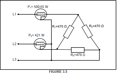
Given:
P1 = 500,65 W
P2 = 421 W
R1= R2= R3 = 470 Ω
VL = 380 V
Calculate the:
3.5.1 Current in each phase of the load (3)
3.5.2 Line current (3)
3.5.3 Total power consumed by the load (3)
3.6 State ONE advantage of a single-phase system with reference to safety and economy. (1)
[30]
QUESTION 4: THREE-PHASE TRANSFORMERS (SPECIFIC)
4.1 Refer to the losses that occur in transformers and answer the questions that follow.
4.1.1 Name TWO types of losses that occur in transformers. (2)
4.1.2 State TWO factors that may contribute to the excessive heating of transformers. (2)
4.2 Describe how electromotive force (EMF) is induced in the secondary windings of transformers. (4)
4.3 Explain why the following are important for effective and efficient use of transformers:
4.3.1 Cooling methods (2)
4.3.2 Protective devices (2)
4.4 A 10 kVA star-delta transformer has primary and secondary line voltages of 6 kV and 500 V respectively.
Given:
S = 10 kVA
VLS = 500 V
VLP = 6 kV
pf = 0,97
Calculate the:
4.4.1 Secondary line current (3)
4.4.2 Transformer ratio (6)
4.4.3 Input power if the power factor is 0,97 (3)
4.4.4 Efficiency of the transformer if the total loss is 80 W (3)
4.5 Explain, with a reason, whether the secondary line current in QUESTION 4.4.1 is higher or lower than the primary line current. (3)
[30]
QUESTION 5: THREE-PHASE MOTORS AND STARTERS (SPECIFIC)
5.1 Define the term synchronous speed of the motor. (2)
5.2 Give the reasons why the following tests are conducted:
5.2.1 Continuity test (2)
5.2.2 Insulation resistance test (2)
5.3 Describe the operation of the squirrel-cage induction motor. (7)
5.4 Refer to FIGURE 5.4 below and answer the questions that follow.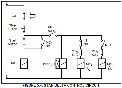
5.4.1 Identify the interlocking contacts. (2)
5.4.2 Explain why MC1 (N/O1) is connected in parallel with the start button. (2)
5.4.3 Describe the operation of the star-delta control circuit. (6)
5.5 A three-phase motor with 18 poles is supplied from a 380 V/50 Hz supply.
Given:
VL = 380 V
f = 50 Hz
Number of poles = 18
Calculate the:
5.5.1 Synchronous speed in r/min (4)
5.5.2 Percentage slip if the rotor speed is 955 r/min (3)
[30]
QUESTION 6: PROGRAMMABLE LOGIC CONTROLLERS (PLCs) (SPECIFIC)
6.1 State THREE disadvantages of a relay control system in comparison to PLC control systems. (3)
6.2 Explain the function of the following PLC hardware components:
6.2.1 Central processing unit (CPU) (2)
6.2.2 Modulator-demodulator (modem) (2)
6.3 Refer to the safety of the PLC and explain why:
6.3.1 Supply lines to the PLC should be installed with either a fuse or a circuit-breaker (2)
6.3.2 Wirings and connections should be checked before connecting the supply to the PLC (2)
6.4 Differentiate between an ON-delay timer contact and an OFF-delay timer contact. (4)
6.5 Refer to FIGURE 6.5 below and answer the questions that follow.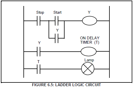
6.5.1 State the application of an ON-delay timer. (2)
6.5.2 Describe the operation in FIGURE 6.5. (5)
6.6 Refer to FIGURE 6.6A and FIGURE 6.6B below and state, with a reason, which figure represents:
6.6.1 An analogue input (2)
6.6.2 A digital input (2)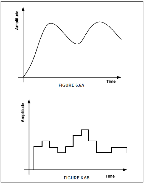
6.7 Refer to FIGURE 6.7.1 below and answer the questions that follow.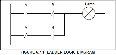
6.7.1 Identify the logic function above. (1)
6.7.2 Complete the truth table in FIGURE 6.7.2 below by writing down only the state of the output.
| A | B | Lamp (output) |
| 0 | 0 | (a) |
| 0 | 1 | (b) |
| 1 | 0 | (c) |
| 1 | 1 | (d) |
(4)
6.8 State ONE application of each of the following sensors:
6.8.1 Light sensor (2)
6.8.2 Temperature sensor (2)
6.9 Refer to FIGURE 6.9 below and draw the PLC ladder logic diagram that would execute the same function.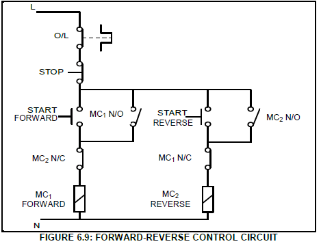
(10)
6.10 Refer to FIGURE 6.10 below and describe the function of each of the following: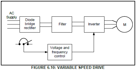
6.10.1 Diode bridge rectifier (2)
6.10.2 Filtering circuit (2)
6.10.3 Inverter (3)
6.11 Give THREE examples of where the variable speed drive may be used. (3)
6.12 Refer to regenerative braking and answer the questions that follow.
6.12.1 Give TWO examples of where this braking method may be used. (2)
6.12.2 Describe regenerative energy. (3)
[60]
TOTAL: 200
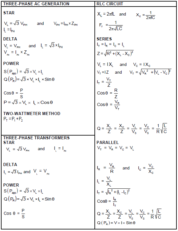
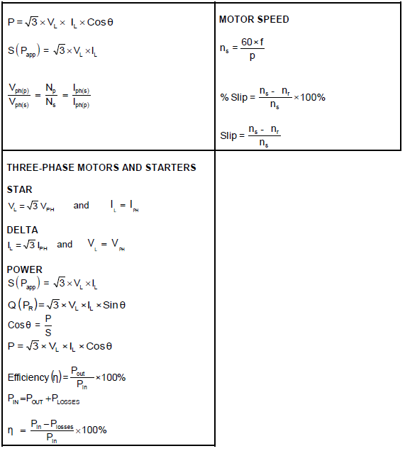
FORMULA SHEET