ELECTRICAL TECHNOLOGY:POWER SYSTEM GRADE 12 MEMORANDUM - NSC PAST PAPERS AND MEMOS MAY/JUNE 2019
Share via Whatsapp Join our WhatsApp Group Join our Telegram GroupELECTRICAL TECHNOLOGY: POWER SYSTEMS
GRADE 12
NATIONAL SENIOR CERTIFICATE EXAMINATIONS
MEMOARANDUM
MAY/JUNE 2019
INSTRUCTIONS TO THE MARKERS
- All questions with multiple answers imply that any relevant, acceptable answer should be considered.
- Calculations:
2.1 All calculations must show the formulae.
2.2 Substitution of values must be done correctly.
2.3 All answers MUST contain the correct unit to be considered.
2.4 Alternative methods must be considered, provided that the correct answer is obtained.
2.5 Where an incorrect answer could be carried over to the next step, the first answer will be deemed incorrect. However, should the incorrect answer be carried over correctly, the marker has to re-calculate the values, using the incorrect answer from the first calculation. If correctly used, the candidate should receive the full marks for subsequent calculations.
2.6 Markers should consider that learner answers may deviate slightly from the guideline; depending on how and where in the calculation rounding off was used. - These marking guidelines are only a guide with model answers. Alternative interpretations must be considered and marked on merit. However, this principle should be applied consistently throughout the marking session at ALL marking centres.
QUESTION 1: OCCUPATIONAL HEALTH AND SAFETY (GENERIC)
1.1 An accident is an unplanned, uncontrolled event ✓ caused by unsafe acts and or unsafe conditions ✓ resulting in a personal injury, illness or the death of an employee. ✓
An accident means an accident arising out of and in the course of an employee’s employment and resulting in personal injury, illness or the death of the employee.
Note: The definition in the textbook is flawed but will be accepted. (3)
1.2 Move in an orderly manner. ✓
Follow the evacuation route as displayed in your workshop. ✓
Move to the designated assembly point in a calm and orderly manner. (2)
1.3 To prevent oneself form being shocked, ✓ therefore precautions must be taken to isolate oneself when rendering assistance.
To prevent injury. (1)
1.4 A third degree burn occurs when all layers of skin have been burnt, ✓ causing permanent skin damage affecting fat, muscle and even bone. ✓
A serious burn deserves 1 mark (2)
1.5 A person who intentionally and recklessly interferes with equipment will cause damages ✓ and this will render equipment unsafe and compromise the safety of the user. ✓ (2)
[10]
QUESTION 2: RLC CIRCUITS (GENERIC)
2.1
2.1.1 Capacitive reactance is the opposition ✓ to an alternating current by the reactive component of a capacitor ✓ in an ac circuit. (2)
2.1.2 Inductive reactance is the opposition ✓ to an alternating current by the reactive component of an inductor ✓ in an ac circuit.
If only the formula is given by the learner = 1 mark
If the formula is accompanied by the correct explanation = 2 marks. (2)
2.2
2.2.1 XL x 2 x π x f x L
= 2 x π x 60 x 44 x10-3
= 16,59 Ω ✓ (3)
2.2.2 XC = 1
2 x π x f x C
= 1 ✓
2 x π x 60 x120 x10-6
= 22,1 Ω (3)
2.2.3 Z √R2 + (XC - XL)2
= √252 + (22.11- 16.59)2
= 25,6 Ω ✓ (3)
2.3
2.3.1 IC = VS
VC
= 220
60
= 3,67 A ✓ (3)
2.3.2 IX = IL - IC
= 6 - 3,67
= 2,33 A ✓ (3)
2.3.3 The phase angle is lagging ✓ because IL is greater than IC.✓ (2)
2.4 2.4.1 At resonance frequency XL = XC
XC = 50,27 Ω (1)
2.4.2 C = 1
XC x 2π x f
= 1
50,27 x 2π x1000
= 3,17 x 10-6
= 3,17 μF (3) ✓
2.4.3 The value of the current will be halved as the circuit resistance is inversely proportional to the applied voltage. ✓
The value of the current will be halved if the resistance is doubled = 1 mark (2)
2.5
2.5.1 fr = 1
2π √L x C
= 1
2π √80 x 10-3 x 33 x 10-6
= 97,95 Hz (3)
2.5.2 I = VS (Z = R at resonance)
Z
= 120
30
= 4 A (3) ✓
2.5.3 VL = I x XL
= 4 x 49,24
= 196,94 V (3)
2.5.4 The voltage across XL is VL = IXL=. ✓
During resonance current is at a maximum. ✓
As a result VL would be higher due to the current being at a maximum. ✓ However because VL = VC the reactive voltage is zero ✓and effectively this voltage increase does not affect the supply voltage.
XL is greater than R, therefore VL will be greater than VR during resonance because the current in a series circuit is common through all components leading to the voltage across the inductor being greater than the supply voltage. (4)
[40]
QUESTION 3: THREE-PHASE AC GENERATION
3.1
3.1.1 The power factor meter is used to measure the power factor.✓ (1)
3.1.2 The Kilowatt-hour meter is used to measure the amount of electrical power consumed ✓ by the load over a certain period of time. ✓ (2)
3.2 Generation✓
- Electricity is generated in power stations. The power stations convert energy from its basic form (fossil fuel, natural gases, coal, nuclear fuel and water action) into electrical energy.✓
- The basic fuel is used to make superheated steam to drive turbines. The turbines drive generators which generate electricity.✓ (3)
Transmission✓
- The generated electricity will be stepped up to a high voltage and then fed into a national grid. ✓
- From the national grid it is transmitted with overhead power lines to different distribution stations. ✓(3)
Distribution✓
- At distribution stations, electricity is further distributed to intermediate substations.✓
- From intermediate substations, it is stepped down to the required level and distributed to consumers. ✓ (commercial buildings, residential places, governmental building, etc) (3)
3.3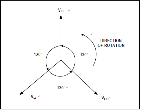 (5)
(5)
3 marks for phases
1 mark for degrees
1 mark for rotation
3.4 Excessive current will be drawn by the system. ✓ More losses will occur in the form of heat ✓and the efficiency of the system will be reduced.✓ (3)
3.5
3.5.1 Current in each phase
IPH = V
R
= 380
470
=0.81A (3)
3.5.2 Line current
IL = √3 x IPH
=√3 x 0.81
= 1.40A (3)
3.5.3 Total power
PT = P1 + P2
= 500.65 + 421
= 921.65W (3)
3.6 Single phase system appliances are cheaper than three-phase appliances. ✓
Single phase voltage is lower than three-phase and therefore safer. (1)
[30]
QUESTION 4: THREE-PHASE TRANSFORMERS
4.1
4.1.1 Copper losses ✓
Iron losses ✓
Dielectric losses
Stray losses (2)
4.1.2 Insufficient circulating air for cooling the transformer. ✓
Insufficient oil in which the transformer is immersed.✓
Constant overloading.
Internal faults (2)
4.2
- When AC voltage is supplied to the primary windings, alternating current will flow in the windings. ✓
- This current will produce alternating magnetic fluxes ✓
- The produced magnetic fluxes will link with the secondary winding through the magnetic core.✓
- When these fluxes link with the secondary winding, an electro-motive-force (EMF) is induced in the secondary. (4)
4.3
4.3.1 It ensures that the:
- Device does not overheat. ✓
- Life expectancy is not reduced. ✓ (2)
4.3.2 To ensure that the transformer is
- Isolated from the supply should internal fault arise. ✓
- Not damaged as a result of a short circuit. ✓ (2)
4.4
4.4.1 Secondary line current
S = √3 x IL x VL
IL = S
√3 x VL
= 10000
√3 x 500
=11.55A(3)✓
4.4.2 Transformer ratio
V ph = VL
√3
= 6000
√3
=3.46kV
VL = Vph
Vph(p) = Np
Vph(s) Ns
= 3460
500
= 7:1
OR
= 6,92 : 1 (6)✓
4.4.3 Input power
Pin = √3 x VL x IL x Cosθ Pin = S x Cosθ
= √3 x 500 x 11.55 x 0.97 = 10000 x 0.97
= 9.70 kW =9.70kW (3)
4.4.4 η = Pin - Ploss x 100
Pin
= 9700 - 80 x 80
9700
= 99.17%(3)✓
4.5 The kVA rating in the primary windings and the secondary windings of a transformer is identical. The secondary line current in question 4.4.1 will be higher than the primary line current, ✓ because the voltage in the secondary windings is less ✓ than voltage in the primary winding. ✓ (3)
[30]
QUESTION 5: THREE-PHASE MOTORS AND STARTERS
5.1 The speed of the rotating magnetic field ✓ in the stator windings. ✓ (2)
5.2
5.2.1 To ensure:
- Earth continuity ✓
- That there is continuity between the ends of each coil. ✓ (2)
5.2.2 To ensure that there is no electrical connection between:
- Each of the three coils ✓
- Any of the three coils and earth. ✓ (2)
5.3
- When a three-phase supply is connected to the stator winding, a rotating magnetic flux is produced. ✓
- This flux will cut the metal rod of the rotor, inducing an e.m.f in it ✓ which is responsible for the flow of current in the rotor. ✓
- This current will create a magnetic flux. ✓
- The stator and rotor magnetic flux will react to each other ✓and a force will be produced. ✓
- The force will cause the rotor to rotate in the direction of the rotating magnetic flux. ✓ (7)
5.4
5.4.1 MC3 (N/C)✓ and MC2 (N/C) ✓ (2)
5.4.2 MC1 (N/O1) is connected in parallel with the start button so that when start button is pressed and released, ✓ current could flow in the circuit through it thus keeping the starter on. ✓
To latch/retain the circuit. (2)
5.4.3
- When the start button is pressed, MC1 will be energised ✓ closing MC1 (N/O1) and MC1 (N/O2).✓
- MC2 will be energised opening the MC2 (N/C) and the motor will run in star and prevent MC3 from being energised and timer T is energised. ✓
- After a pre-set time, the energised timer will open T(N/C) and close T(N/O), de-energising MC2 ✓ and MC2 (N/C) will close again, thus enabling MC3 to be energised. ✓
- MC3 will be energised and MC3 (N/C) will open and the motor will run in delta and prevent MC2 from being energised. ✓
- The motor continues to run in delta until the stop button is pressed or the overload is activated. (6)
5.5
5.5.1 Synchronous speed
The total of 18 poles = 6 poles per phase = 3 pole pairs per phase (p = 3) ✓
NS = 60 x f
p
= 60 x 50
3
= 1000 rpm (4)
5.5.2 Percentage slip
= NS - Nr x 100
NS
= 1000 - 955 x 100
1000
= 4.5%(3)✓
[30]
QUESTION 6: PROGRAMMABLE LOGIC CONTROLLERS (PLC)
6.1 Relays requires regular maintenance and repair. ✓
Uses much more energy. ✓
It requires a lot of space to be wired. ✓
It has lower response time.
When a single relay develops faults in a panel, it takes much time to locate and fix which might delay production. (3)
6.2
6.2.1 The function of the central processing unit is to execute the instructions as per the inputs ✓ and provide the outputs. ✓ (2)
6.2.2 The function of the modem is to isolate the processor against damage ✓ from random high current or voltage spikes ✓ and to pass information signals in and out of the processor (2)
6.3
6.3.1 Supply lines to the PLC should be installed with either a fuse or a circuit breaker to prevent ✓ excessive over-current. ✓ (2)
6.3.2 Wirings and connections should be checked before connecting the supply to the PLC to ensure that wiring is correctly connected, ✓ to prevent damage ✓ to the unit. (2)
6.4 An ON-delay timer contact would not operate ✓ until a pre-set delay time has passed,✓ after it has first been energised.
An OFF-delay timer contact will immediately operate ✓and remain in this active state once energized. Its contacts will only deactivate and open after the pre-set time has passed,✓ after it has been de-energised. (4)
6.5
6.5.1 An ON delay timer is applied in the control circuit to prevent the light from being switched on ✓before the pre-set time lapses after the start button has been pressed. ✓ (2)
6.5.2 When the start button is pressed, coil Y will be energised✓ closing latching circuit Y and contactor Y.✓
The timer will start timing until the pre-set time has lapsed.
Contactor T will close ✓and the lamp will be switched “ON”✓
The Lamp will remain switched “ON” until the Stop button is pressed. ✓ (5)
6.6
6.6.1 An analogue input is represented by FIGURE 6.6 A,✓ because it varies freely within a certain range ✓ (2)
6.6.2 A digital input is represented by FIGURE 6.6 B, ✓because it varies with definite steps which is digital in nature. ✓ (2)
6.7
6.7.1 Exclusive OR-gate ✓ (1)
6.7.2
- 0(1)
- 1(1)
- 1 (1)
- 0(1)
6.8
6.8.1 Light sensor is applied in:
Cell phones: ✓✓ The device uses the ambient light sensor to automatically control the brightness of the screen in situation where the intensity of light is high or low.
To sense the light intensity level. (2)
6.8.2 Temperature sensor is applied in:
Motor cars radiator: ✓✓ If the temperature of the water circulating in the engine exceed a preset value, the sensor will warn the driver by flicking the light on the dashboard.
To sense the temperature level. (2)
6.9 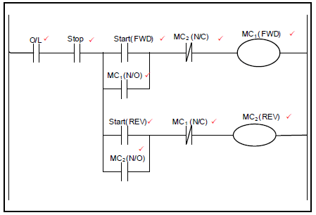 (10)
(10)
6.10
6.10.1 Diode bridge rectifier converts an AC supply voltage✓ to a DC voltage. ✓ (2)
6.10.2 Filtering circuit smooths the AC ripple ✓to ensure a pure DC voltage on the DC rail.✓ (2)
6.10.3 The inverter inverts the DC voltage✓ back to an AC voltage✓ at a variable frequency✓ which will then control the speed of the motor as it depends on the frequency supplied by the VSD. (3)
6.11 The VSD is used in:
Water pumping systems✓
Heating system✓
Exhaust air system, dust extraction and fan system✓
Variable air volume air conditioning system (3)
6.12
6.12.1 Regenerative braking methods may be used in:
Lifts✓
Cranes✓
Electrical locomotives (2)
6.12.2 Regenerative energy is energy recovered from the motor✓ when it slows down by converting mechanical energy to electrical energy✓ which can be either used immediately or stored until needed.✓ (3)
[60]
TOTAL: 200