MECHANICAL TECHNOLOGY: AUTOMOTIVE GRADE 12 MEMORANDUM - NSC EXAMS PAST PAPERS AND MEMOS NOVEMBER 2018
Share via Whatsapp Join our WhatsApp Group Join our Telegram GroupMECHANICAL TECHNOLOGY: AUTOMOTIVE
GRADE 12
NSC EXAMS
PAST PAPERS AND MEMOS NOVEMBER 2018
MEMORANDUM
QUESTION 1: MULTIPLE-CHOICE QUESTIONS (GENERIC)
1.1 A ✔ (1)
1.2 C ✔ (1)
1.3 A ✔ (1)
1.4 B ✔ (1)
1.5 D ✔ (1)
1.6 A ✔ (1)
TOTAL QUESTION 1: [6]
QUESTION 2: SAFETY (GENERIC)
2.1 Angle grinder: (Before using)
- The safety guard must be in place before starting. ✔
- Protective shields must be placed around the object being grinded to protect the people around. ✔
- Use the correct grinding disc for the job. ✔
- Make sure that there are no cracks in the disc before you start. ✔
- Protective clothing and eye protection are essential. ✔
- Check electrical outlets and cord/plugs for any damages. ✔
- Ensure that lockable switch is disengaged. ✔
- Ensure that the disc and the nut are well secured. ✔
- Ensure that the removable handle is secured. ✔
- Remove all flammable material from the area. ✔
- Secure the work piece. ✔
- (Any 2 x 1) (2)
2.2 Welding goggles:
- To protect your eyes against sparks ✔
- To protect your eyes against heat ✔
- To be able to see where to weld ✔
- To protect your eyes from UV rays / bright light ✔
- To protect your eyes from smoke ✔
- (Any 2 x 1) (2)
2.3 PPE for Hydraulic press:
- Overall ✔
- Safety shoes ✔
- Safety goggle ✔
- Leather gloves ✔
- Leather apron ✔
- Face shield ✔
- (Any 2 x 1) (2)
2.4 Workshop layouts:
- Process layout ✔
- Product layout ✔ (2)
2.5 Employer’s responsibility regarding first-aid:
- Provision of first-aid equipment ✔
- First aid training ✔
- First-aid services by qualified personnel ✔
- Any first aid procedures ✔
- Display first aid safety signs ✔
- First aid personnel must be identified by means of arm bands or relevant personal signage ✔
- (Any 2 x 1) (2)
TOTAL QUESTION 2: [10]
QUESTION 3: MATERIALS (GENERIC)
3.1 Bending test:
- Ductility ✔✔
- Malleability ✔✔
- Brittleness ✔✔
- Flexibility ✔✔
- (Any 1 x 2) (2)
3.2 Heat-treatment:
3.2.1 Annealing:
- To relieve internal stresses ✔
- To soften the steel ✔
- To make the steel ductile ✔
- To refine the grain structure of the steel ✔
- To reduce the brittleness of the steel ✔
- (Any 2 x 1) (2)
3.2.2 Case hardening:
- To produce a wear resistant surface ✔ and it must be tough enough internally ✔ at the core to withstand the applied loads.
- Hard case ✔ and tough core. ✔
- (Any 1 x 2) (2)
3.3 Tempering process:
- To reduce ✔ the brittleness ✔ caused by the hardening process.
- Relieve ✔ strain ✔ caused during hardening process.
- Increase ✔ the toughness ✔ of the steel.
- (Any 1 x 2) (2)
3.4 Factors for heat-treatment processes:
- Heating temperature / Carbon content ✔
- Soaking (Time period at temperature) / Size of the work piece ✔
- Cooling rate / Quenching rate ✔ (3)
3.5 Hardening of steel:
- Steel is heated to 30 – 50°C above the higher critical temperature. (AC3) ✔
- It is then kept at that temperature to ensure (soaking) that the whole structure is Austenite. ✔
- The steel is then rapidly cooled by quenching it in clean water, brine or oil. ✔ (3)
TOTAL QUESTION 3: [14]
QUESTION 4: MULTIPLE-CHOICE QUESTIONS (SPECIFIC)
4.1 C ✔ (1)
4.2 B ✔ (1)
4.3 D ✔ (1)
4.4 D ✔ (1)
4.5 A ✔ (1)
4.6 C ✔ (1)
4.7 A ✔ (1)
4.8 D ✔ (1)
4.9 A / C ✔ (1)
4.10 A ✔ (1)
4.11 D ✔ (1)
4.12 D ✔ (1)
4.13 A ✔ (1)
4.14 A ✔ (1)
TOTAL QUESTION 4: [14]
QUESTION 5: TOOLS AND EQUIPMENT (SPECIFIC)
5.1 Equipment:
5.1.1 Compression tester ✔ (1)
5.1.2
- A – Flexible piping / hose / tubing ✔
- B – Adaptor screw / Fitting / Attachment / Connector ✔
- C – Gauge ✔
- D – Pressure release valve ✔ (4)
5.1.3 Compression Tester:
- It measures the pressure created, ✔ when the piston is at top dead centre on power stroke. ✔ (2)
5.2 Cylinder leakage:
- To check whether the engine leaks gases ✔ from the cylinder during the compression stroke. ✔ (2)
5.3 Gas Analyser:
- To ensure ✔ an accurate reading. ✔
- o prevent ✔ a lean reading. ✔
- (Any 1 x 2 ) (2)
5.4 Function of a computerized diagnostic scanner:
- Scans all systems ✔ on the vehicle.
- Informs what adjustments can be made after diagnosis ✔
- (Any 1 x 1 ) (1)
5.5 Bubble gauge camber procedure:
- Mount the bubble gauge on to the straightened wheel ✔
- Zero the bubble gauge at the gauge zero scale ✔
- Take the reading on the camber scale ✔
- Do the same for the other wheel ✔ (4)
5.6 Dynamic balance on wheels:
- The plane of imbalance ✔
- The extent of the unbalancing forces ✔
- The sense of direction of these forces (clockwise or counter clockwise) ✔
- Determine the location of weight placement ✔
- Magnitude of the weights ✔
- The run-out of the tyre and wheel assembly ✔
- (Any 3 x 1 ) (3)
5.7 Purpose of turn tables:
- To make it possible to turn ✔ the front wheels in or out ✔ to check ✔ the wheel angles. ✔ (4)
TOTAL QUESTION 5: [23]
QUESTION 6: ENGINES (SPECIFIC)
6.1 Static balancing of the crankshaft:
- The crankshaft is in static when the mass in all directions ✔ from the centre of rotation is equal while it is at rest. ✔ (2)
6.2 Cylinder layouts:
6.2.1 V - engine layout ✔ (1)
6.2.2 In line (straight) engine layout ✔ (1)
6.3 Firing order in an engine:
- By removing the tappet cover and determining which are intake valves and which are exhaust valves ✔
- Rotating the engine in the direction in which it turns. ✔
- Watch the order in which one set of valves, inlet or exhaust operates ✔
- This will give the order in which the inlet stroke or exhaust stroke occurs ✔
- The power strokes occur in the same order ✔
OR - Cylinder 1 must be at TDC on power stroke ✔
- Remove the distributor cap ✔
- Ensure to turn the engine in the correct direction of rotation ✔
- Determine the direction of rotation of the rotor ✔
- Trace the firing order by the HT leads ✔
- (Any 1 x 5 ) (5)
6.4 Firing order of engines:
6.4.1 Four cylinder in-line engine:
- 1,3,4,2; or ✔
- 1,2,4,3 ✔
- (Any 1 x 1 ) (1)
6.4.2 V6-cylinder engine:
- 1,4,2,5,3,6 ✔
- 1,2,3,4,5,6 ✔
- 1,6,5,4,3,2 ✔
- 1,4,5,6,3,2 ✔
- (Any 1 x 1 ) (1)
6.5 Turbo charger:
6.5.1 Turbocharger:
- A – Compressor air inlet ✔
- B – Turbine housing ✔
- C – Turbine exhaust gas outlet ✔
- D – Turbine wheel ✔
- E – Turbine exhaust gas inlet ✔
- F – Compressed air outlet ✔
- G – Compressor wheel ✔ (7)
6.5.2 Turbocharger advantages:
- More power / speed / boost is obtained from an engine with the same capacity ✔
- There is no power loss as the turbocharger is driven by exhaust gasses ✔
- Improved fuel consumption ✔
- The effect of height above sea level is eliminated ✔
- Generally, cheaper than superchargers ✔
- Any ( 2 x 1) (2)
6.6 Terminology:
6.6.1 Boost:
- Refers to the increase in manifold pressure ✔ that is generated by the turbocharger in the intake that exceeds the normal atmospheric pressure. ✔ (2)
6.6.2 Turbo lag:
- It is a delay ✔ between pushing on the accelerator and feeling turbo kick in. ✔ or
- The time ✔ it takes the turbo charger to reach operating speed. ✔
- (Any 1 x 2) (2)
6.7 Purpose of waste gate:
- It diverts exhaust gases ✔ away from the turbine wheel to regulate the turbine speed ✔ and consequently boost pressure. (2)
6.8 Oil cooler:
- To cool (prevent overheating) the oil ✔ that lubricates the turbocharger bearings and shaft. ✔ (2)
TOTAL QUESTION 6: [28]
QUESTION 7: FORCES (SPECIFIC)
7.1 Torque:
- Torque is the twisting effort ✔ transmitted by a rotating shaft or wheel. ✔
- Turning force applied ✔ over a centre of a round object. ✔
- (Any 1 x 2) (2)
7.2 Clearance volume:
- This is the volume of the space ✔ above the crown of the piston at TDC. ✔ (2)
7.3 Method to increase compression ratio:
Remove shims between the cylinder block and cylinder head. ✔
- Fit thinner cylinder head gasket. ✔
- Machine metal from cylinder head. ✔
- Skim metal from cylinder block. ✔
- Fit a piston with a higher crown. ✔
- Fit a crankshaft with a longer stroke. ✔
- Increase the bore of the cylinders. / bigger pistons. ✔
- (Any 2 x 1) (2)
7.4 Calculation of compression ratio:
7.4.1
- Swept Volume = πD2 × L ✔
4
= π (7,5)2 8,0 ✔
4
353,43 cm3 ✔ (3)
7.4.2
- Compression Ratio = SV + CV
CV
CV = SV
CR - 1
= 353,43
8,5 1
= 353,43
7,5
= 47,12 cm ✔ (3)
7.4.3 New compression ratio:
- Sweptvolume = πD2 × L
4
= π7,82 × 8
4
= 382,27 cm ✔ - New compression Ratio = SV + 1
CV
= 382,27 + 1
47,12
= 8,11 + 1:1
= 9.11:1
OR - New compression Ratio = SV + CV
CV
= 382.27 + 47.12
47.12
= 9.11:1 ✔(6)
7.5 Calculations: Power:
7.5.1 IndicatedPower = P × L × A × N × n
- P = 1400 kPa
L = 110
1000
= 0,11 m - A = πD2
4
= π0,102
4
= 7,85 x 10⁻³m2 ✔ ✔ - N = 3600
60 × 2
= 30 r/s ✔ ✔
n 4 cylinders - IndicatedPower = P × L × A × N × n
= [1400 × 103] × 0,11 × [7,85 × 10-3] × 30 × 4
= 145068 W
= 145,07 kW (8)
7.5.2 T = F × r
- (75 × 10) × 0,45
= 337,5N.m ✔ - Brake power = 2π × N × T
= 2π × 60 × 337,5 ✔
= 127234,5 W
= 127,23 kW ✔ (4)
7.5.3 Mechanicalefficiency = BP 100%
IP
- = 127,23 × 100%
145,07 00 %
= 87,70% ✔ (2)
TOTAL QUESTION 7: [32]
QUESTION 8: MAINTENANCE (SPECIFIC)
8.1 Gas analyser:
- Exhaust gasses ✔
- CO gasses ✔
- CO2 gasses ✔
- SO2 gasses ✔
- NOx gasses ✔
- HC gasses ✔
- O2 gasses ✔
- (Any 1 x 1) (1)
8.2 Specification for gas analysis:
- % Hydrocarbon / HC ✔
- % Carbon monoxide / CO ✔
- % Carbon dioxide / CO2 ✔
- % Nitrogen oxide / NOx ✔
- % Sulphur dioxide / SO2 ✔
- (Any 3 x 1) (3)
8.3 Cylinder leakage test: (Results)
- Hissing noise at air intake ✔
- Hissing noise at exhaust pipe ✔
- Hissing noise in dipstick hole ✔
- Hissing noise under tappet cover ✔
- Bubbles in radiator water ✔
- Hissing noise at adjacent cylinders ✔
- (Any 2 x 1) (2)
8.4 Cylinder Leakage test: (Causes)
- Worn cylinders ✔
- Worn piston ✔
- Worn piston rings ✔
- Leaking inlet valve ✔
- Leaking exhaust valve ✔
- Leaking cylinder head gasket ✔
- Cracked cylinder head / block ✔
- (Any 2 x 1) (2)
8.5 Compression test procedures:
- Get the engine to normal operating temperature. ✔
- Disconnect the fuel supply and ignition system. ✔
- Remove spark plugs. ✔
- Fit the compression tester ✔
- Depress the throttle and crank the engine a few revolutions. ✔
- Record and compare the pressure reading for each cylinder with manufacturers specifications. ✔ (6)
8.6 Reasons for low oil pressure:
- Worn oil pump ✔
- Blocked oil pump screen/filter/strainer in the sump ✔
- Worn main, big-end and camshaft bearings ✔
- Blocked or restricted oil filter ✔
- Dirty or contaminated oil ✔
- Oil leaks ✔
- Too little oil in engine ✔
- Incorrect grade (viscosity) of oil ✔
- Pressure relief valve spring too weak or damaged ✔
- Plunger / Ball stuck in open position ✔
- Dirt stuck between ball and seat ✔
- (Any 2 x 1) (2)
8.7 Cooling system pressure test:
- Start engine and allow to heat up. Fit radiator pressure tester to radiator. ✔
- Pressurize the cooling system according to manufacture’s specification. ✔
- Watch the pressure for a while, if it drops there is a leak. ✔
- Make a visual check for leaks. ✔
- Install radiator cap to tester and pump tester, the cap should release air at its rated pressure. ✔
- Check the rubber seal for cracks and damage. ✔
- Check the vacuum valve for free movement and operation. ✔ (7)
TOTAL QUESTION 8: [23]
QUESTION 9: SYSTEMS AND CONTROL (AUTOMATIC GEARBOX) (SPECIFIC)
9.1 Differences between an automatic and manual gearbox:
- There is no clutch pedal in a motor vehicle with an automatic gearbox. / There is a clutch pedal in a motor vehicle with a manual gearbox. ✔
- There is no need to change gears, the shifting of the gears happens automatically. ✔
- Automatic transmission uses thin oil while manual gearbox uses thicker oil. ✔
- Automatic transmission uses torque converter while manual gearbox uses clutch assembly. ✔
- (Any 2 x 1) (2)
9.2 Advantages of automatic gearbox:
- It reduces driver fatigue ✔
- It ensures great reduction of wheel spin under bad road conditions ✔
- The vehicle can be stopped suddenly without the engine stalling ✔
- The system dampens all engine torsional vibrations ✔
- Easier to drive (e.g. Disabled person with one leg) ✔
- (Any 2 x 1) (2)
9.3 Torque converter:
9.3.1 Torque converter function:
- Transfers engine torque to the transmission. ✔
- It multiplies the engine torque to the transmission. ✔
- Provides a direct-drive, or mechanical link from the engine to the transmission. ✔
- The torque converter dampens all engine torsional vibrations. ✔
- The torque converter acts as a flywheel. ✔
- (Any 2 x 1) (2)
9.3.2 Parts:
- A – One-way clutch / Turbine ✔
- B – Turbine / Impeller ✔
- C – Pump ✔
- D – Turbine shaft ✔
- E – Gearbox housing ✔ (5)
9.4 Single epicyclic gear train:
- Overdrive forward ✔
- Overdrive reverse ✔
- Gear reduction forward ✔
- Gear reduction reverse ✔
- Direct drive ✔
- Neutral ✔
- (Any 5 x 1) (5)
9.5 Purpose of gear ratio in the gearbox:
- It is used in order to utilise the usable torque ✔ developed in a relatively limited speed range of the engine over a greater road speed range. ✔
- Allows different speeds ✔ depending on the different loads. ✔
- (Any 1 x 2) (2)
TOTAL QUESTION 9: [18]
QUESTION 10: SYSTEMS AND CONTROL (AXLES, STEERING GEOMETRY AND ELECTRONICS) (SPECIFIC)
10.1 Preliminary wheel alignment checks:
- Kerb mass (tank full of petrol, spare wheel and tools) against the manufacturer’s specifications. ✔
- Uneven wear on the tyre. ✔
- Tyre pressure. ✔
- Run-out on the wheels; check wheel nuts with torque wrench. ✔
- Correct preload on the wheel (hub) bearings. ✔
- Kingpins and bushes. ✔
- Suspension ball joints for wear, locking and lifting. ✔
- Suspension bushes for excessive free movement. ✔
- Steering box play and whether secure on chassis. ✔
- Tie-rod ends. ✔
- Sagged springs, this includes riding height. ✔
- Ineffective shock absorbers. ✔
- Spring U-bolts. ✔
- Chassis for possible cracks and loose cross-members. ✔
- Wheels must be balanced ✔
- Wheel alignment specifications ✔
- Drive shafts / CV-joints ✔
- (Any 5 x 1) (5)
10.2 Caster
10.2.1 Negative ✔ Caster ✔ (2)
10.2.2 Parts:
- A – Contact point of king pin centre line ✔
- B – King pin ✔
- C – Perpendicular line / vertical line / normal line ✔
- D – Negative caster angle ✔
- E – Centre line of king pin ✔
- F – Front of vehicle / Direction of wheel motion ✔
- G – Point of wheel contact / Wheel ✔ (7)
10.2.3 Negative caster angle is the forward tilt ✔ of the kingpin at the top, ✔ viewed from the side. ✔ (3)
10.3 Toe-out: 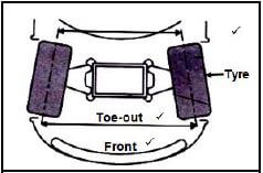 (3)
(3)
10.4 Purpose of the king pin inclination:
- To bring the front wheels back to the straight-ahead position ✔ after rounding a corner without any driver effort. ✔
- Reduce ✔ the scrub radius. ✔
- (Any 1 x 2) (2)
10.5 Catalytic converter:
- Oxidation ✔
- Reduction ✔
- (Any 1 x 1) (1)
10.6 Purpose of the speed control system:
- The purpose of the speed control system is to control the throttle opening ✔ and to keep the vehicle speed constant. ✔ (2)
10.7 Advantage of speed control:
- Driver fatigue is reduced. ✔
- The set speed is controlled constantly. ✔
- Improved fuel consumption. ✔
- A consistently controlled speed helps to prevent speeding fines. ✔
- (Any 2 x 1) (2)
10.8 Fuel pressure regulator:
- Fuel pressure regulator regulates the fuel pressure in relation to the manifold pressure. ✔ (1)
10.9 Output frequency of an alternator:
- Increase the turns of wire on the stationary coil. ✔
- Increase the magnetic fields. ✔
- Increase the rotational frequency at which the magnet rotates. ✔
- (Any 2 x 1) (2)
10.10 Stator and stator windings:
- To provide a core which concentrates the magnetic lines of force onto the stator windings ✔
- To provide a coil into which a voltage is induced which is used to charge the battery. ✔
- (Any 1 x 1) (1)
10.11 Function of rotor assembly:
- Is to provide a rotating electro-magnet. ✔ (1)
TOTAL QUESTION 10: [32]
TOTAL: 200d