MECHANICAL TECHNOLOGY: WELDING AND METALWORK GRADE 12 MEMORANDUM - NSC EXAMS PAST PAPERS AND MEMOS NOVEMBER 2018
Share via Whatsapp Join our WhatsApp Group Join our Telegram GroupMECHANICAL TECHNOLOGY: WELDING AND METALWORK
GRADE 12
NSC EXAMS
PAST PAPERS AND MEMOS NOVEMBER 2018
MEMORANDUM
QUESTION 1: MULTIPLE-CHOICE QUESTIONS (GENERIC)
1.1 A ✔ (1)
1.2 C ✔ (1)
1.3 A ✔ (1)
1.4 B ✔ (1)
1.5 D ✔ (1)
1.6 A ✔ (1)
TOTAL QUESTION 1: [6]
QUESTION 2: SAFETY (GENERIC)
2.1 Angle grinder: (Before using)
- The safety guard must be in place before starting. ✔
- Protective shields must be placed around the object being grinded to protect the people around. ✔
- Use the correct grinding disc for the job. ✔
- Make sure that there are no cracks in the disc before you start. ✔
- Protective clothing and eye protection are essential. ✔
- Check electrical outlets and cord/plugs for any damages. ✔
- Ensure that lockable switch is disengaged. ✔
- Ensure that the disc and the nut are well secured. ✔
- Ensure that the removable handle is secured. ✔
- Remove all flammable material from the area. ✔
- Secure the work piece. ✔
- (Any 2 x 1) (2)
2.2 Welding goggles:
- To protect your eyes against sparks ✔
- To protect your eyes against heat ✔
- To be able to see where to weld ✔
- To protect your eyes from UV rays / bright light ✔
- To protect your eyes from smoke ✔
- (Any 2 x 1) (2)
2.3 PPE for Hydraulic press:
- Overall ✔
- Safety shoes ✔
- Safety goggle ✔
- Leather gloves ✔
- Leather apron ✔
- Face shield ✔
- (Any 2 x 1) (2)
2.4 Workshop layouts:
- Process layout ✔
- Product layout ✔ (2)
2.5 Employer’s responsibility regarding first-aid:
- Provision of first-aid equipment ✔
- First aid training ✔
- First-aid services by qualified personnel ✔
- ∙ Any first aid procedures ✔
- Display first aid safety signs ✔
- First aid personnel must be identified by means of arm bands or relevant personal signage ✔
- Any 2 x 1) (2)
TOTAL QUESTION 2: [10]
QUESTION 3: MATERIALS (GENERIC)
3.1 Bending test:
- Ductility ✔✔
- Malleability ✔✔
- Brittleness ✔✔
- Flexibility ✔✔
- Any 1 x 2) (2)
3.2 Heat-treatment:
3.2.1 Annealing:
- To relieve internal stresses ✔
- To soften the steel ✔
- To make the steel ductile ✔
- To refine the grain structure of the steel ✔
- To reduce the brittleness of the steel ✔
- (Any 2 x 1) (2)
3.2.2 Case hardening:
- To produce a wear resistant surface ✔ and it must be tough enough internally ✔ at the core to withstand the applied loads.
- Hard case ✔ and tough core. ✔
- (Any 1 x 2) (2)
3.3 Tempering process:
- To reduce ✔ the brittleness ✔ caused by the hardening process.
- Relieve ✔ strain ✔ caused during hardening process.
- Increase ✔ the toughness ✔ of the steel.
- (Any 1 x 2) (2)
3.4 Factors for heat-treatment processes:
- Heating temperature / Carbon content ✔
- Soaking (Time period at temperature) / Size of the work piece ✔
- Cooling rate / Quenching rate ✔ (3)
3.5 Hardening of steel:
- Steel is heated to 30 – 50°C above the higher critical temperature. (AC3) ✔
- It is then kept at that temperature to ensure (soaking) that the whole structure is Austenite. ✔
- The steel is then rapidly cooled by quenching it in clean water, brine or oil. ✔ (3)
TOTAL QUESTION 3: [14]
QUESTION 4: MULTIPLE-CHOICE QUESTIONS (SPECIFIC)
4.1 B ✔ (1)
4.2 A ✔ (1)
4.3 B ✔ (1)
4.4 B ✔ (1)
4.5 A ✔ (1)
4.6 B ✔ (1)
4.7 D ✔ (1)
4.8 D ✔ (1)
4.9 C ✔ (1)
4.10 C ✔ (1)
4.11 A ✔ (1)
4.12 D ✔ (1)
4.13 B ✔ (1)
4.14 B ✔ (1)
TOTAL QUESTION 4: [14]
QUESTION 5: TERMINOLOGY (TEMPLATES) (SPECIFIC)
5.1 Template loft:
The template loft is separated from the workshop because…
- it is quieter. ✔
- the lighting is better. ✔
- all equipment is at hand. ✔
- it is a permanent base. ✔
- marking on the floor enhance accuracy. ✔
- (Any 2 x 1) (2)
5.2 Purpose of purlins:
- The purlins support ✔ the roof covering ✔
- Stabilizes ✔ the trusses. ✔
- (Any 1 x 2) (2)
5.3 A steel ring calculation:
5.3.1 Dimensions of the required material:
- Mean diameter = Outside diameter - plate thickness
= 880 - 50
= 830mm - Mean circurmference = π × Meandiameter = ×
= π × 830
= 2607,52mm ✔ - 2608 mm of 50 x 50 mm ✔ square steel bar is required to fabricate the ring. (7)
5.3.2 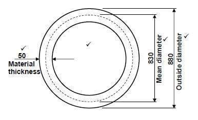
5.4 Resistance weld symbols:
5.4.1 Spot weld ✔ (1)
5.4.2 Seam weld ✔ (1)
5.5 Welding symbols:
- A. Tail ✔
- B. Weld symbol (Fillet weld) ✔
- C. Pitch of weld ✔
- D. Site weld ✔
- E. Arrow ✔
- F. Weld all round ✔ (6)
TOTAL QUESTION 5: [23]
QUESTION 6: TOOLS AND EQUIPMENT (SPECIFIC)
6.1. Working Principles:
6.1.1 Guillotine:
- A bottom cutting blade is fixed horizontally. ✔
- With a top cutting blade moving downwards. ✔
- It is driven by an electric motor, flywheel, gearbox and axle ✔ by eccentric motion / action / hydraulic action. ✔
- OR
- It is activated manually by foot ✔ with lever action. ✔ (4)
6.1.2 Bending rolls:
- A bending roll has two fixed rollers next to each other rotating in unison (Manually or Electrical motor). ✔
- A third roller is adjustable, moving in between the two rollers. ✔
- The third roller applies downward pressure onto the metal. ✔
- That causes the metal to deflect and ultimately form the round shape desired. ✔ (4)
6.2. Regulators on gas cylinders:
- Regulators reduce ✔ the cylinder pressure ✔ to operating or working pressure. ✔ (3)
6.3 Press machine:
- The press machine is used for installing ✔ or removing ✔ components on mechanical devices / machines. ✔
- To press ✔ profiles ✔ onto material ✔
- (Any 1 x 3) (3)
6.4 MIGS/MAGS welding process:
- A – Weld pool / weld bead / molten metal ✔
- B – Electrode wire / electrode ✔
- C – Gas shroud / electrical contact / nozzle / contact tip ✔
- D – Shielding gas ✔ (4)
TOTAL QUESTION 6: [18]
QUESTION 7: FORCES (SPECIFIC)
7.1 Forces in members:
SCALE: Vector diagram 1 mm = 5 N 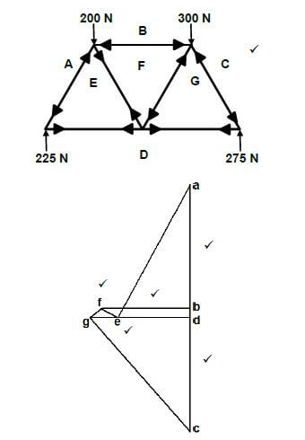 (20)
(20)
MEMBER | MAGNITUDE | NATURE |
AE | 260 N ✔ | STRUT ✔ |
BF | 135 N ✔ | STRUT ✔ |
CG | 317,5 N ✔ | STRUT ✔ |
FG | 27,5 N ✔ | STRUT ✔ |
ED | 130 N ✔ | TIE ✔ |
EF | 27,5 N ✔ | TIE ✔ |
GD | 160 N ✔ | TIE ✔ |
NOTE:
- Use a tolerance of 2 mm + and – on the vector diagram.
- = a tolerance of 10 N + and – on the answer.
7.2 Bending moments: 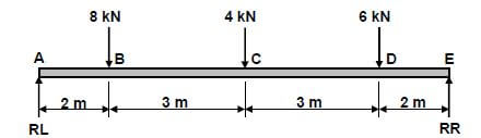
7.2.1 Moments about RR
- RL × 10 = (8× 8)+ (4× 5) +(6× 2)
RL = 96
10
= RL 9,6kN ✔
Moments about RL - RR × 10= (6× 8) +(4 × 5) +(8×2)
RR = 84
10
= RR 8,4kN (8)
7.2.2 Bending moments at point A, B, C, D and E:
- Scale2 mm = 1 kN.m
Momentat A = 0 kN.m
B = RL × 2 = 19,2 kN.m
C = (RL × 5) - (8×3) = 24 kN.m
D =(RL×8) -(8×6) - (4×3) = 16,8 kN.m
E = (RL×10) -(8×8) - (4×5) - (6×2) = 0 kN.m (5)
7.2.3 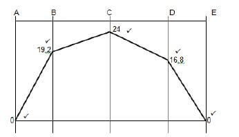 (5)
(5)
NOTE:
- Use a tolerance of 2 mm + and – on the bending moment diagram.
7.3 Stress and strain:
- A = πd2
4
A = π(0,02)2
4
A = 0,314 ×10-3m2 - Stress = Load
Area
Load = Stress c Area
Load = (80 × 106) × (0,314 × 10-3)
Load = 25,133kN ✔(7)
TOTAL QUESTION 7: [45]
QUESTION 8: JOINING METHODS (WELD INSPECTION) (SPECIFIC)
8.1 Factors to be observed during oxy-acetylene welding:
- Correct flame for the work on hand. ✔
- Correct angle of welding torch and welding rod. ✔
- Depth penetration and amount of fusion. ✔
- The rate of progress along the joint. ✔
- The distance of the nozzle from the parent metal. ✔
- (Any 2 x 1) (2)
8.2 Abbreviation 'HAZ':
- Heat Affected Zone ✔ (1)
8.3 Causes of weld defects:
8.3.1 Spatter:
- Disturbance in the molten weld pool. ✔
- Too low welding voltages. ✔
- Too high welding current / amps. ✔
- Inadequate shielding gas flow. ✔
- Too fast travel speed ✔
- Arc length too long ✔
- Wet electrode ✔
- Wrong polarity ✔
- Arc length too short ✔
- Wrong included electrode angle ✔
- Wrong electrode used ✔
- Arc blow ✔
- (Any 2 x 1) (2)
8.3.2 Undercutting:
- Too fast travel speed ✔
- Rapid solidification ✔
- Too low arc voltage ✔
- Arc length too long ✔
- Excessive welding current ✔
- Too slow movement over weld ✔
- Current / amps too high ✔
- Electrode too big ✔
- Wrong electrode ✔
- Wrong included electrode angle ✔
- Excessive weaving ✔
- Wrong joint design ✔
- (Any 2 x 1) (2)
8.3.3 Incomplete penetration:
- Welding current too low ✔
- Too fast travel speed ✔
- Incorrect electrode angle ✔
- Poor edge preperation ✔
- Insufficient root gap ✔
- Electrode too big ✔
- Wrong electrode ✔
- No pre-heating done ✔
- Wrong shielding gas used ✔
- Too long arc ✔
- (Any 2 x 1) (2)
8.4 Types of cracks:
8.4.1 Transverse cracks:
- Pre-heating the base metal ✔
- Using lower strength consumables / welding rod ✔
- Slow cooling after welding ✔
- Use clamping device. ✔
- Weld toward the unrestrained side of the weld. ✔
- (Any 2 x 1) (2)
8.4.2 Centreline cracks:
- Ensure that width-to-depth ratio is 1:1. ✔
- Decrease the current to decrease excess penetration. ✔
- Decreasing welding voltage setting or slowing travel speed to achieve a flat to convex weld surface. ✔
- Use clamping device. ✔
- (Any 2 x 1) (2)
8.5 Differences between non-destructive and destructive tests: ∙ Non-destructive test does not destroy the welded joint. ✔
- Destructive test destroys the welded joint. ✔ (2)
8.6 Ultrasonic test:
- No defects will occurs during a ultrasonic test ✔✔
- Detect internal ✔ flaws as well as surface flaws. ✔
- Porosity ✔✔
- Slag inclusions ✔✔
- Cracks ✔✔
- Any 1 x 2) (2)
8.7 Nick break test for internal defects:
- Slag inclusion ✔
- Porosity ✔
- Lack of fusing ✔
- Oxidised metal ✔
- Burned metal ✔
- (Any 2 x 1) (2)
8.8 Machinability test:
- To determine the hardness ✔ and strength ✔of the welded joint.
- To determine ✔ the machinability. ✔
- Any 1 x 2) (2)
8.9 Visual requirements of welds:
- Shape of the profile ✔
- Uniformity of the surface ✔
- Overlap ✔
- Free from any external defects ✔
- Penetration bead ✔
- Root groove ✔
- (Any 2 x 1) (2)
TOTAL QUESTION 8: [23]
QUESTION 9: JOINING METHODS (STRESSES AND DISTORTION) (SPECIFIC)
9.1 Residual stress:
- Residual stresses are stresses that exist ✔ in a metal after cooling / welding. ✔ (2)
9.2 Factors affecting grain size:
- The amount of cold work. ✔
- The temperature and time of annealing process. ✔
- The composition and constitution. ✔
- The recrystallisation temperature of cold worked metal. ✔
- The melting point. ✔
- (Any 2 x 1) (2)
9.3 Quenching medias:
- Oil ✔
- Water ✔
- Sand ✔
- Air ✔
- Brine / Salt water ✔
- Lime ✔
- Liquid salts ✔
- Molten lead ✔
- Ash ✔
- (Any 2 x 1) (2)
9.4 Weld distortion:
- Distortion in a weld results from the uneven expansion and contraction (warping) ✔ of the weld metal ✔ and adjacent base metal ✔ during the heating and cooling cycle ✔ of the welding process. (4)
9.5 Factors that affect distortion and residual stress:
- If the expansion that occurs when metal is heated is resisted ✔ then deformation will occur. ✔
- When contraction that occurs on cooling is resisted ✔then a stress will be applied. ✔
- If this applied stress causes movement ✔ then distortion occurs. ✔
- If the applied stress does not cause movement ✔ then there will be residual stress in the welded joint. ✔
- (Any 2 x 2) (4)
9.6 Result when metal is cooled rapidly:
- Rapid cooling of metal results in large temperature differences ✔ between the internal and external areas ✔ of the metal that set up stresses, ✔ which cause cracks ✔ on the surface.
- It will harden ✔✔ and the grain structure ✔ will change. ✔
- (Any 1 x 4) (4)
TOTAL QUESTION 9: [18]
QUESTION 10: MAINTENANCE (SPECIFIC)
10.1 Reasons maintenance:
- Promote cost saving ✔
- Improves safety ✔
- Increases equipment efficiency ✔
- Fewer equipment failure ✔
- Improves reliability of equipment ✔
- (Any 2 x 1) (2)
10.2 Lockout on machines:
- To ensure that nobody can turn on the machine ✔ while maintenance is being carried out. ✔ (2)
10.3 Reasons for service records:
- Assist in the monitoring of the condition of the machines. ✔
- Assist in upholding warrantees. ✔
- Assist in keeping a history of maintenance and repairs. ✔
- (Any 2 x 1) (2)
10.4 Methods of reducing friction:
- By reducing both drill speed and feed speed. ✔
- By applying lubrication. (cutting fluid) ✔
- Use the correct drill bit ✔
- Drill a pilot hole ✔
- (Any 2 x 1) (2)
TOTAL QUESTION 10: [8]
QUESTION 11: TERMINOLOGY (DEVELOPMENT) (SPECIFIC)
11.1 Use of transformers:
- Transformers are used to connect ✔ ducting sections of dissimilar ✔ shapes to each other. ✔ (3)
11.2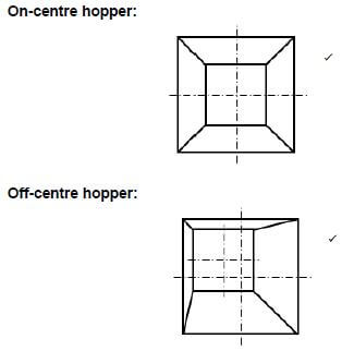 @1
@1
11.3 Truncated cone: 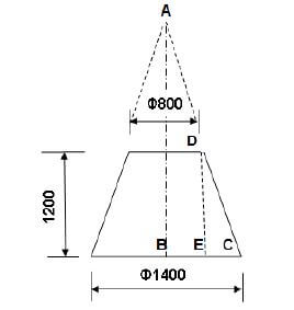
11.3.1 Base circumference:
- Circumference = π × Basediameter
= π × 1400
= 4398,23 mm ✔(3)
11.3.2 Main radius (AC):
- Triangles ABC and CED has the same shape:
AC : DC BC :EC
Thus AC = BC
DC EC
From where AC = BC × DC
EC
and CE = Base Dia - 800
2
= 1400 - 800
2
CE = 300 mm
For : DC
DC2 = DE2 + CE2
DC = √12002 + 3002
DC = 1236,93mm
rounded = 1237mm
AC = BC × DC
EC
= 700 × 1237
300
= 2886,17mm ✔ ✔
rounded 2886mm (10)
11.3.3 Small radius (AD):
- AD = AC - DC
= 2886 - 1237
AD = 1649 mm(1649,24mm) ✔ (3)
TOTAL QUESTION 11: [21]
GRAND TOTAL: 200