ELECTRIC CIRCUITS QUESTIONS AND ANSWERS
Share via Whatsapp Join our WhatsApp Group Join our Telegram GroupWorked example 1
In this circuit the battery has an emf of 24 V and an internal resistance of 2 Ω. Voltmeter V1 is connected as shown and voltmeter V2 is connected over the three resistors in parallel. The resistance of the connectors and of the ammeter may be ignored.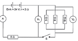
- Switch S is open.
- What is the reading on V1?
- What is the reading on V2?
- Switch S is now closed. Calculate:
- the total resistance in the circuit.
- the current that flows through the 8 Ω resistor.
- the charge that flows past a cross section of the 8 Ω resistor in one minute.
Solutions
- V1 = 24 V (when S is open, no current flows and V1 is connected across the battery)
- V2 = 0 V (S is open, no current flows, V is connected on one side of the switch, ∴ only to one pole of the battery
1 = 1 + 1 + 1 = 1 + 1 + 1 = 6 + 2 + 1 = 9
R1 R1 R2 R3 3 9 18 18 18
- Rexternal = Rseries + R|| = 8 + 2 = 10 Ω and
Rexternal = Rext + rint = 10 + 2 = 12 Ω - The 8 Ω resistor is connected in series ∴ the total current flows through it
∴ calculate the total current (I) that flows through the circuit.
Rtot = V tot
Itot
∴ 12 = 24
Itot
∴ Itot = 24 = 2 A
12 - I = Q
Δt
∴ 2 = Q
(1)(60)
∴ Q = (2)(1)(60) = 120 C
This is a current that flows through all the circuits.
- Rexternal = Rseries + R|| = 8 + 2 = 10 Ω and
Remember: Convert minutes to seconds: x 60 or hours to seconds: x 3600
Remember: Current is the rate at which electric charge passes a fixed point in a conductor.
I ∝ Q
I = Δt
Q
Activity 1
In the circuit below the battery has an emf of 24 V and an unknown internal resistance. Voltmeter V1 is connected across the battery. The resistance of the connectors and of the ammeter may be ignored. When switch S is closed, voltmeter V2 reads 4 V and voltmeter V1 reads 20 V.
- Calculate:
- The reading on ammeter A2. (2)
- The reading on ammeter A1. (5)
- The resistance of resistor R. (4)
- The internal resistance of the battery. (3)
- The energy converted in resistor R in 10 minutes. (3)
- Switch S is now opened. Will the reading on voltmeter V1 increase, decrease or remain constant? Explain. (6)
[23]
Solutions
|
Activity 2
Multiple Choice questions:
Related Items
- Which ONE of the following is the unit of measurement for the rate of flow of charge?
- watt
- coulomb
- volt
- ampere (2)
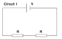
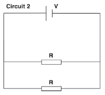
- The two resistors in circuit 1 below are identical. They are connected in series to a cell of emf V and negligible internal resistance. The power dissipated by each resistor is P.

The two resistors are now connected in parallel, as shown in circuit 2 below.
The power dissipated by each resistor in the circuit 2 is...- 2P
- 4P
- 8P
- 16P (2)
[4]
| Solutions 1. D (2) 2. B (2) [4] |
Activity 3
In the circuit represented below, the battery has an emf of 10 V and an unknown internal resistance. Voltmeter V1 is connected across the battery and voltmeter V2 is connected across the open switch S. The resistance of the connecting wires and ammeter can be ignored.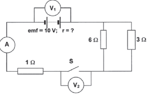
Switch S is open
- What is the reading on V1? (2)
- What is the reading on V2? (2)
When Switch S is closed, the reading on V1 drops to 7,5 V. - What is the reading on V2? (2)
- Calculate the reading on the ammeter. (8)
- Calculate the internal resistance of the battery. (5)
[19]
Solutions
|
Activity 4
The headlights of a car are connected in parallel to a 12 V battery, as shown in the simplified circuit diagram below. The internal resistance of the battery is 0,1 Ω and each headlight has a resistance of 1,4 Ω. The starter motor is connected in parallel with the headlights and controlled by the ignition switch, S2. The resistance of the connecting wires may be ignored.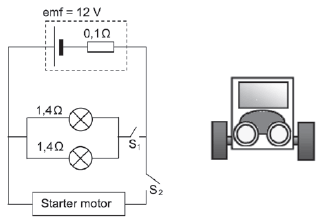
- State Ohm’s Law in words. (2)
- With only switch S1 closed, calculate the following:
- Effective resistance of the two headlights (3)
- Potential difference across the two headlights (4)
- Power dissipated by one of the headlights (3)
- Ignition switch S2 is now closed (whilst S1 is also closed) for a short time and the starter motor, with VERY LOW RESISTANCE, rotates. How will the brightness of the headlights be affected while switch S2 is closed? Write down only INCREASES, DECREASES or REMAINS THE SAME.
Fully explain how you arrived at the answer. (9)
[21]
Solutions
|